
English Manual
Page 1
... assistance, free of charge. CUSTOMER HOT LINE: 1-888-825-2588 Mon.-Fri., 6 a.m.-6 p.m. Write the serial number in this manual before using this manual for future reference. Save this equipment. Serial Number Decal (under seat) QUESTIONS? NTS78740 Serial No. MST USER'S MANUAL CAUTION Read all precautions and instructions in the space above for future reference. Visit our website at www.nordictrack.com new products, prizes, fitness tips...
... assistance, free of charge. CUSTOMER HOT LINE: 1-888-825-2588 Mon.-Fri., 6 a.m.-6 p.m. Write the serial number in this manual before using this manual for future reference. Save this equipment. Serial Number Decal (under seat) QUESTIONS? NTS78740 Serial No. MST USER'S MANUAL CAUTION Read all precautions and instructions in the space above for future reference. Visit our website at www.nordictrack.com new products, prizes, fitness tips...
English Manual
Page 2
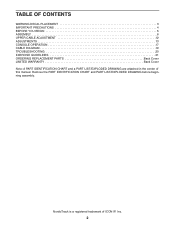
Remove the PART IDENTIFICATION CHART and PART LIST/EXPLODED DRAWING before beginning assembly. NordicTrack is a registered trademark of this manual. TABLE OF CONTENTS WARNING DECAL PLACEMENT 3 IMPORTANT PRECAUTIONS 4 BEFORE YOU BEGIN 5 ASSEMBLY 6 UPPER CABLE ADJUSTMENT 12 ADJUSTMENTS 13 CONSOLE OPERATION 17 CABLE DIAGRAM 19 TROUBLESHOOTING 20 EXERCISE GUIDELINES 21 ORDERING REPLACEMENT PARTS Back Cover LIMITED WARRANTY Back Cover Note: A PART IDENTIFICATION CHART and a PART LIST/EXPLODED DRAWING are attached in the center of ICON IP, Inc. 2
Remove the PART IDENTIFICATION CHART and PART LIST/EXPLODED DRAWING before beginning assembly. NordicTrack is a registered trademark of this manual. TABLE OF CONTENTS WARNING DECAL PLACEMENT 3 IMPORTANT PRECAUTIONS 4 BEFORE YOU BEGIN 5 ASSEMBLY 6 UPPER CABLE ADJUSTMENT 12 ADJUSTMENTS 13 CONSOLE OPERATION 17 CABLE DIAGRAM 19 TROUBLESHOOTING 20 EXERCISE GUIDELINES 21 ORDERING REPLACEMENT PARTS Back Cover LIMITED WARRANTY Back Cover Note: A PART IDENTIFICATION CHART and a PART LIST/EXPLODED DRAWING are attached in the center of ICON IP, Inc. 2
English Manual
Page 4
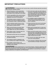
... performing an exercise that the cables remain on the pulleys. This is being adjusted. 17. The resistance system is used with the seat in one of the three positions closest to ensure that all users of the resistance system are on the pulleys at all instructions in place and fully tightened each time the resistance system is not designed to support a maximum user weight of 300...
... performing an exercise that the cables remain on the pulleys. This is being adjusted. 17. The resistance system is used with the seat in one of the three positions closest to ensure that all users of the resistance system are on the pulleys at all instructions in place and fully tightened each time the resistance system is not designed to support a maximum user weight of 300...
English Manual
Page 5
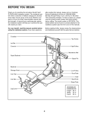
... for selecting the innovative NordicTrack® FUTURA 2600 resistance system. BEFORE YOU BEGIN Thank you have questions after reading this manual, please call our Customer Service Department toll-free at 1-888-825-2588, Monday through Friday, 6 a.m. Crossbar Lat Bar Console Top Frame High Pulley Squat Backrest Resistance Bar Squat Pin Backrest Storage Knob Curl Pad Curl Bar Leg Lever Low Pulley Row Plate Seat Seat Knob Base Plate ASSEMBLED DIMENSIONS: Height: 86 in. To...
... for selecting the innovative NordicTrack® FUTURA 2600 resistance system. BEFORE YOU BEGIN Thank you have questions after reading this manual, please call our Customer Service Department toll-free at 1-888-825-2588, Monday through Friday, 6 a.m. Crossbar Lat Bar Console Top Frame High Pulley Squat Backrest Resistance Bar Squat Pin Backrest Storage Knob Curl Pad Curl Bar Leg Lever Low Pulley Row Plate Seat Seat Knob Base Plate ASSEMBLED DIMENSIONS: Height: 86 in. To...
English Manual
Page 6
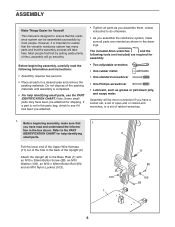
... Button Bolt (83), and an M10 Nylon Locknut (103). 2 103 1 71 88 106 83 6 Before beginning assembly, make sure all parts in the back of the packing materials until assembly is completed. • For help identifying small parts. However, it has been pre-attached. • Tighten all parts as you assemble them, unless instructed to do otherwise. • As you assemble the resistance...
... Button Bolt (83), and an M10 Nylon Locknut (103). 2 103 1 71 88 106 83 6 Before beginning assembly, make sure all parts in the back of the packing materials until assembly is completed. • For help identifying small parts. However, it has been pre-attached. • Tighten all parts as you assemble them, unless instructed to do otherwise. • As you assemble the resistance...

English Manual
Page 9
... the Spacer and the Large Pulleys (14) used in steps 8 and 9 (refer to the Upright (2) with an M12 x 62mm Button Bolt (81) and an M12 Nylon Locknut (13). Do not tighten the Bolt yet. 121 11 90 13 68 81 14 2 17 18 86 15 Metal 2 121 Cover 54 86 70 18 16 Groove 9 Attach a Small Guide Spacer (18), the Crossbar...
... the Spacer and the Large Pulleys (14) used in steps 8 and 9 (refer to the Upright (2) with an M12 x 62mm Button Bolt (81) and an M12 Nylon Locknut (13). Do not tighten the Bolt yet. 121 11 90 13 68 81 14 2 17 18 86 15 Metal 2 121 Cover 54 86 70 18 16 Groove 9 Attach a Small Guide Spacer (18), the Crossbar...

English Manual
Page 10
... Cable is routed as shown in step 10. 12. Attach the Leg Lever (56) to a Pulley Bracket (10) with a 14 Leg Station Pin (60). 11. Make sure that the Cable is on the other Pulley Bracket (10) with an M10 x 64mm Button Bolt (80), an M10 Thick Washer (54), and an M10 Nylon Locknut (103). Press a Pulley Bracket (10) onto the Resistance Bar (9). Attach the Pulley to the Leg...
... Cable is routed as shown in step 10. 12. Attach the Leg Lever (56) to a Pulley Bracket (10) with a 14 Leg Station Pin (60). 11. Make sure that the Cable is on the other Pulley Bracket (10) with an M10 x 64mm Button Bolt (80), an M10 Thick Washer (54), and an M10 Nylon Locknut (103). Press a Pulley Bracket (10) onto the Resistance Bar (9). Attach the Pulley to the Leg...
English Manual
Page 11
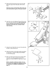
...using the resistance system, turn on the console and change the resistance setting as described in the Seat Carriage (44). Rod Slot 44 32 44 17. 15. Make sure that all parts have been properly tightened. Hold the Backrest Frame vertically over the Seat Carriage and 32 slide the rod into the 16 slot in UPPER CABLE ADJUSTMENT... two M6 x 16mm Screws (41). 43 18. Slide the Pad Tube (50) into the Leg Lever (56). 15 Slide two Large Foam Pads (52) onto the Pad Tube. Attach the Curl Pad (43) to the Leg 56 Lever (56) and the Leg (5) in ADJUSTMENTS, beginning on the following...
...using the resistance system, turn on the console and change the resistance setting as described in the Seat Carriage (44). Rod Slot 44 32 44 17. 15. Make sure that all parts have been properly tightened. Hold the Backrest Frame vertically over the Seat Carriage and 32 slide the rod into the 16 slot in UPPER CABLE ADJUSTMENT... two M6 x 16mm Screws (41). 43 18. Slide the Pad Tube (50) into the Leg Lever (56). 15 Slide two Large Foam Pads (52) onto the Pad Tube. Attach the Curl Pad (43) to the Leg 56 Lever (56) and the Leg (5) in ADJUSTMENTS, beginning on the following...

English Manual
Page 12
...) together near a Large Pulley (14). which is attached to adjust the Upper Cable tension. 1. Do not hook the ends of the system to be adjusted. Plug in the resistance system as shown. The Upper Cable tension is first used. UPPER CABLE ADJUSTMENT After completing the assembly of the resistance system, the tension on the Upper Cable (121) will need to the Large Pulley (14) as shown...
...) together near a Large Pulley (14). which is attached to adjust the Upper Cable tension. 1. Do not hook the ends of the system to be adjusted. Plug in the resistance system as shown. The Upper Cable tension is first used. UPPER CABLE ADJUSTMENT After completing the assembly of the resistance system, the tension on the Upper Cable (121) will need to the Large Pulley (14) as shown...

English Manual
Page 13
... the 90mm Pulley (40) in the Leg (5), and attach it through the Leg (5) as shown when attaching it to one end of the Lower Cable (120) with a Cable Clip (94). Route the hook end of the Leg Lever Cable (102) under the Cable. Slide a Cotter Pin (113) onto the Leg Station Pin. Also, refer to the accompanying exercise guide to see the correct form for important information about how...
... the 90mm Pulley (40) in the Leg (5), and attach it through the Leg (5) as shown when attaching it to one end of the Lower Cable (120) with a Cable Clip (94). Route the hook end of the Leg Lever Cable (102) under the Cable. Slide a Cotter Pin (113) onto the Leg Station Pin. Also, refer to the accompanying exercise guide to see the correct form for important information about how...

English Manual
Page 14
... Strap (not shown) to the ends of the lower cable with a Cable Clip (94). 53 94 56 14 Remove the Curl Pad (43) from the resistance system when performing an exercise that does not require it. 43 42 59 5 ATTACHING THE CURL BAR To use the Curl Bar (53), first attach the leg lever to the leg (see ATTACHING THE HIGH PULLEYS on page 13). Attach the Lat Bar...
... Strap (not shown) to the ends of the lower cable with a Cable Clip (94). 53 94 56 14 Remove the Curl Pad (43) from the resistance system when performing an exercise that does not require it. 43 42 59 5 ATTACHING THE CURL BAR To use the Curl Bar (53), first attach the leg lever to the leg (see ATTACHING THE HIGH PULLEYS on page 13). Attach the Lat Bar...

English Manual
Page 15
... the slot (see ADJUST- 20 ING THE SQUAT ARM above). Then, insert a Squat Pin (66) into the Squat Carriage. 27 19 ATTACHING THE SQUAT STATION To use the Backrest (35) in an inclined position, secure the Seat Carriage (44) at the adjustment hole in the Upright (2). To use the squat station, first remove the backrest (see ADJUSTING THE SEAT on page 16). Rest...
... the slot (see ADJUST- 20 ING THE SQUAT ARM above). Then, insert a Squat Pin (66) into the Squat Carriage. 27 19 ATTACHING THE SQUAT STATION To use the Backrest (35) in an inclined position, secure the Seat Carriage (44) at the adjustment hole in the Upright (2). To use the squat station, first remove the backrest (see ADJUSTING THE SEAT on page 16). Rest...

English Manual
Page 16
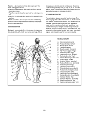
...). To perform row exercises, the hip strap must be attached to the desired position. STORING THE RESISTANCE SYSTEM To store the resistance system, first remove the Curl Pad (not shown) and the Leg Lever (not shown) from the resistance system. WARNING: Make sure that the pin rests at the position closest to the new location. Secure the Seat Carriage (44) at...
...). To perform row exercises, the hip strap must be attached to the desired position. STORING THE RESISTANCE SYSTEM To store the resistance system, first remove the Curl Pad (not shown) and the Leg Lever (not shown) from the resistance system. WARNING: Make sure that the pin rests at the position closest to the new location. Secure the Seat Carriage (44) at...
English Manual
Page 17
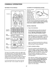
... when using the resistance system. MANUAL OPERATION Program Buttons Main Display Resistance Display 1. Plug in the trans- Important: Always plug in the main display. 17 Note: When the power is changing, the motor will then be heard. When a program is running a program, press and hold down one of the console, follow the steps at the right. To use the manual mode of the buttons. Select a resistance setting. To select a different resistance setting, first make sure that no cables...
... when using the resistance system. MANUAL OPERATION Program Buttons Main Display Resistance Display 1. Plug in the trans- Important: Always plug in the main display. 17 Note: When the power is changing, the motor will then be heard. When a program is running a program, press and hold down one of the console, follow the steps at the right. To use the manual mode of the buttons. Select a resistance setting. To select a different resistance setting, first make sure that no cables...

English Manual
Page 18
... main display. Plug the transformer into a 120-volt outlet (see the included exercise guide. Press any part of the program, press the NEXT button to advance to resume exercising. 2. It is on page 17). The recommended resistance setting and the recommended numbers of sets and repetitions that you perform the exercise, the console will appear in the three displays below each display. 5. If you complete during your workout, unplug...
... main display. Plug the transformer into a 120-volt outlet (see the included exercise guide. Press any part of the program, press the NEXT button to advance to resume exercising. 2. It is on page 17). The recommended resistance setting and the recommended numbers of sets and repetitions that you perform the exercise, the console will appear in the three displays below each display. 5. If you complete during your workout, unplug...
English Manual
Page 20
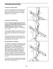
.... Adjust the tension as the resistance system is being pulled, there may be heard. RECALIBRATING THE CONSOLE To recalibrate the Console (67), first plug in the CONSOLE OPERATION section, starting on page 17. 20 15 121 117 67 this message is displayed repeatedly but no cable is used. Use the resistance system as the motor moves between the lowest and highest resistance settings. TROUBLESHOOTING CLEANING THE BAR GUIDES Over...
.... Adjust the tension as the resistance system is being pulled, there may be heard. RECALIBRATING THE CONSOLE To recalibrate the Console (67), first plug in the CONSOLE OPERATION section, starting on page 17. 20 15 121 117 67 this message is displayed repeatedly but no cable is used. Use the resistance system as the motor moves between the lowest and highest resistance settings. TROUBLESHOOTING CLEANING THE BAR GUIDES Over...

English Manual
Page 21
... exercise by changing the number of resistance that you can tone your energy level is an essential part of an effective exercise program. Your muscles will leave you . Work your limits and select the amount of repetitions or sets per- Cross Training Cross training is right for each workout with 3 sets of 8 repetitions for 20 to a moderate percentage of their maximum capacity. WARMING UP Begin each exercise, and moving...
... exercise by changing the number of resistance that you can tone your energy level is an essential part of an effective exercise program. Your muscles will leave you . Work your limits and select the amount of repetitions or sets per- Cross Training Cross training is right for each workout with 3 sets of 8 repetitions for 20 to a moderate percentage of their maximum capacity. WARMING UP Begin each exercise, and moving...
English Manual
Page 22
... life. Soleus (front of thigh) I J K L M N O P Q R S T U V W X MUSCLE CHART A. Adductor (inner thigh) O. List the date, the exercises performed, the resistance used to make exercise a regular and enjoyable part of arm) S. Obliques (waist) E. Hamstring (back of sets and repetitions completed. Sternomastoid (neck) B. Hip Flexors (upper thigh) G. Sartorius (front of calf) K. Spinae Erectors (lower back) U. Record your arms and legs. Tibialis Anterior (front of thigh) J. Latissimus...
... life. Soleus (front of thigh) I J K L M N O P Q R S T U V W X MUSCLE CHART A. Adductor (inner thigh) O. List the date, the exercises performed, the resistance used to make exercise a regular and enjoyable part of arm) S. Obliques (waist) E. Hamstring (back of sets and repetitions completed. Sternomastoid (neck) B. Hip Flexors (upper thigh) G. Sartorius (front of calf) K. Spinae Erectors (lower back) U. Record your arms and legs. Tibialis Anterior (front of thigh) J. Latissimus...
English Manual
Page 24
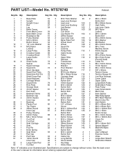
... Cap Button Bolt # 1 Exercise Guide 50 3 Pad Tube 94 4 Cable Clip # 1 Video 51 6 19mm Round 95 2 Long Handle # 1 Large Allen Wrench Inner Cap 96 2 Short Handle # 1 Small Allen Wrench 52 6 Large Foam Pad 97 1 Hip Strap 53 1 Curl Bar 98 1 Ankle Strap Note: "#" indicates a non-illustrated part. Qty. See the back cover of the user's manual for information about ordering replacement parts. Specifications are subject to change without...
... Cap Button Bolt # 1 Exercise Guide 50 3 Pad Tube 94 4 Cable Clip # 1 Video 51 6 19mm Round 95 2 Long Handle # 1 Large Allen Wrench Inner Cap 96 2 Short Handle # 1 Small Allen Wrench 52 6 Large Foam Pad 97 1 Hip Strap 53 1 Curl Bar 98 1 Ankle Strap Note: "#" indicates a non-illustrated part. Qty. See the back cover of the user's manual for information about ordering replacement parts. Specifications are subject to change without...
English Manual
Page 27
...; FUTURA 2600 resistance system) • The SERIAL NUMBER of the product (see the front cover of this manual) • The KEY NUMBER and DESCRIPTION of the part(s) (see the PART LIST and EXPLODED DRAWING in the center of this manual) LIMITED WARRANTY WHAT IS COVERED-The entire NordicTrack® FUTURA 2600 resistance system ("Product") is authorized to use , costs of removal, installation or other warranties and any and all defects in China © 2004 ICON...
...; FUTURA 2600 resistance system) • The SERIAL NUMBER of the product (see the front cover of this manual) • The KEY NUMBER and DESCRIPTION of the part(s) (see the PART LIST and EXPLODED DRAWING in the center of this manual) LIMITED WARRANTY WHAT IS COVERED-The entire NordicTrack® FUTURA 2600 resistance system ("Product") is authorized to use , costs of removal, installation or other warranties and any and all defects in China © 2004 ICON...


