
AJSD965 User Guide
Page 2
... safe operation, the three-pin plug must have three cores and be inserted only into a standard three-pin power outlet which generates strong magnetic fields may infringe the right of the magnetic fields away from the unit before operation. CAUTION: TO REDUCE THE RISK OF FIRE OR SHOCK HAZARD, REFER CHANGE OF SWITCH SETTING INSIDE THE DECK TO QUALIFIED SERVICE PERSONNEL...
... safe operation, the three-pin plug must have three cores and be inserted only into a standard three-pin power outlet which generates strong magnetic fields may infringe the right of the magnetic fields away from the unit before operation. CAUTION: TO REDUCE THE RISK OF FIRE OR SHOCK HAZARD, REFER CHANGE OF SWITCH SETTING INSIDE THE DECK TO QUALIFIED SERVICE PERSONNEL...
AJSD965 User Guide
Page 4
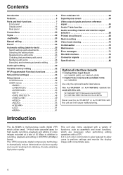
... (deck-to-deck 25 Switch settings and adjustments 25 Selecting the editing mode 26 Registering the edit points 26 Checking and previewing edit points 27 Modifying edit points 28 Executing and reviewing automatic editing . . . . . .29 Audio split editing 30 Variable memory editing 32 PF (Programmable Function) functions 33 Setup (initial settings 34 Setup menus 35 SYSTEM menu 38 USER menus 40
... (deck-to-deck 25 Switch settings and adjustments 25 Selecting the editing mode 26 Registering the edit points 26 Checking and previewing edit points 27 Modifying edit points 28 Executing and reviewing automatic editing . . . . . .29 Audio split editing 30 Variable memory editing 32 PF (Programmable Function) functions 33 Setup (initial settings 34 Setup menus 35 SYSTEM menu 38 USER menus 40
AJSD965 User Guide
Page 5
Switching between 525i and 625i TV systems By selecting the setting (setup menu item No. 070) that does not support the recording and playback of UMID information is connected to this VTR as the time code. In addition, even if a VTR that matches the video input signal TV system (525i or 625i), the signals of the existing DVCPRO (25 Mbps) format. Direct audio channel mixing By operating the buttons on the...
Switching between 525i and 625i TV systems By selecting the setting (setup menu item No. 070) that does not support the recording and playback of UMID information is connected to this VTR as the time code. In addition, even if a VTR that matches the video input signal TV system (525i or 625i), the signals of the existing DVCPRO (25 Mbps) format. Direct audio channel mixing By operating the buttons on the...
AJSD965 User Guide
Page 7
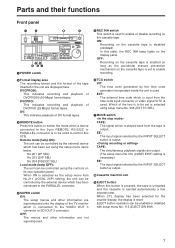
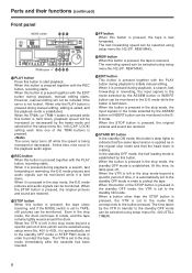
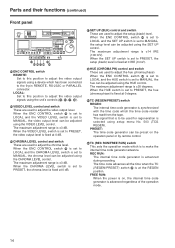
... display, the display is disabled (inhibited). EJECT button operation can be controlled by the external device which has been connected to the PARALLEL connector. 4 SUPER switch ON: The setup menus and other information are output. (The setup menu No.310 (CONFI EDIT) setting is necessary.) EE: The input signal selected by the time code generator incorporated inside the unit is used to control this state, the REC INH lamp lights on its own operation...
... display, the display is disabled (inhibited). EJECT button operation can be controlled by the external device which has been connected to the PARALLEL connector. 4 SUPER switch ON: The setup menus and other information are output. (The setup menu No.310 (CONFI EDIT) setting is necessary.) EE: The input signal selected by the time code generator incorporated inside the unit is used to control this state, the REC INH lamp lights on its own operation...
AJSD965 User Guide
Page 8
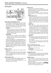
... button is established. ON OFF POWER 2X REMOTE DVCPRO 50 DVCPRO DV SUPER REC INH TCG MODE ON ON INT TAPE OFF OFF EXT EE XL/L/M-cassette EJECT COUNTER ASSEM VIDEO CUE TC INSERT RESET CH 1 CH 2 CH 3 CH 4 PF 1 PF 2 PF 3 PF 4 STAND BY PLAYER RECORDER SET SEARCH SHTL SLOW PUSH JOG HEADPHONES AUDIO MIX PREVIEW/ METER INPUT SELECT REVIEW AUTO EDIT PREROLL FULL/FINE VIDEO AUDIO A IN AUDIO...
... button is established. ON OFF POWER 2X REMOTE DVCPRO 50 DVCPRO DV SUPER REC INH TCG MODE ON ON INT TAPE OFF OFF EXT EE XL/L/M-cassette EJECT COUNTER ASSEM VIDEO CUE TC INSERT RESET CH 1 CH 2 CH 3 CH 4 PF 1 PF 2 PF 3 PF 4 STAND BY PLAYER RECORDER SET SEARCH SHTL SLOW PUSH JOG HEADPHONES AUDIO MIX PREVIEW/ METER INPUT SELECT REVIEW AUTO EDIT PREROLL FULL/FINE VIDEO AUDIO A IN AUDIO...
AJSD965 User Guide
Page 9
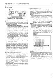
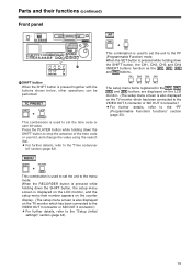
... with an RS-422A serial interface remote control connector (9 pins). Each time it is pressed, it is first returned to the STILL position. SHTL (shuttle) mode: When the dial is turned and set using setup menu No. 320 (VAR FWD MAX) and No. 321 (VAR REV MAX). The SLOW speed in each direction can now be used to operate the recorder (this button is pressed, its own...
... with an RS-422A serial interface remote control connector (9 pins). Each time it is pressed, it is first returned to the STILL position. SHTL (shuttle) mode: When the dial is turned and set using setup menu No. 320 (VAR FWD MAX) and No. 321 (VAR REV MAX). The SLOW speed in each direction can now be used to operate the recorder (this button is pressed, its own...
AJSD965 User Guide
Page 11
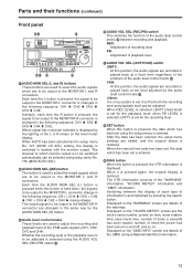
... has been manufactured using the headphones. These missing or lighted pixels will not work. The volume level of the headphone output and monitor output can be recorded. It is also possible to switch the input signals to the internal reference signal selected on the front panel or issue a tape transport instruction from the controller. VIDEO: Each time the VIDEO button is pressed, the input video signal selection is switched in the...
... has been manufactured using the headphones. These missing or lighted pixels will not work. The volume level of the headphone output and monitor output can be recorded. It is also possible to switch the input signals to the internal reference signal selected on the front panel or issue a tape transport instruction from the controller. VIDEO: Each time the VIDEO button is pressed, the input video signal selection is switched in the...
AJSD965 User Guide
Page 13
...) information. 13 Each time the L button is pressed, the signal to be output to the MONITOR R connector are the deck's serial number, power-on time, drum rotation time, tape travel time, number of times a cassette has been loaded, number of the warnings. X AUDIO VOL SEL (REC/PB) switch This switches the function of the "WARNING" information, "HOURS METER" information and "UMID" information. It is changed in the following sequence: CH1 5 CH2 5 CH3 5 CH4 5 CUE. Displayed...
...) information. 13 Each time the L button is pressed, the signal to be output to the MONITOR R connector are the deck's serial number, power-on time, drum rotation time, tape travel time, number of times a cassette has been loaded, number of the warnings. X AUDIO VOL SEL (REC/PB) switch This switches the function of the "WARNING" information, "HOURS METER" information and "UMID" information. It is changed in the following sequence: CH1 5 CH2 5 CH3 5 CH4 5 CUE. Displayed...
AJSD965 User Guide
Page 14
... REC RUN DIAG LOCAL MANUAL MANUAL MANUAL MANUAL PRESET FREE RUN \ a ]^_` b \ ENC CONTROL switch REMOTE: Set to this position to adjust the video output signals using the unit's controls ] VIDEO LEVEL control and switch These are used to adjust the setup (black) level. REC RUN: The internal time code generator is ±30 degrees. The maximum adjustment range is synchronized with the time code which has been connected to adjust the video output level. When the CHROMA LEVEL switch is set to MANUAL, the chroma level...
... REC RUN DIAG LOCAL MANUAL MANUAL MANUAL MANUAL PRESET FREE RUN \ a ]^_` b \ ENC CONTROL switch REMOTE: Set to this position to adjust the video output signals using the unit's controls ] VIDEO LEVEL control and switch These are used to adjust the setup (black) level. REC RUN: The internal time code generator is ±30 degrees. The maximum adjustment range is synchronized with the time code which has been connected to adjust the video output level. When the CHROMA LEVEL switch is set to MANUAL, the chroma level...
AJSD965 User Guide
Page 15
... PF4 buttons are displayed on the LCD monitor. (The setup menu screen is also displayed on the TV monitor which has been connected to the VIDEO OUT 3 connector or SDI OUT 3 connector.) OFor further details, refer to stop the advance of the time code or user bit, and change the value using the search dial. OFor further details, refer to set the time code or user bit value. MENU SHIFT RECORDER + MENU This...
... PF4 buttons are displayed on the LCD monitor. (The setup menu screen is also displayed on the TV monitor which has been connected to the VIDEO OUT 3 connector or SDI OUT 3 connector.) OFor further details, refer to stop the advance of the time code or user bit, and change the value using the search dial. OFor further details, refer to set the time code or user bit value. MENU SHIFT RECORDER + MENU This...
AJSD965 User Guide
Page 16
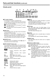
... This lights when the REMOTE button 3 (page 7) has been set to the remote mode. 4 INPUT SELECT display area The characters corresponding to the extent that no signals have been selected is being recorded on the input signal in E-E mode. VIDEO Y PB PR : Analog component video signals (option) CMPST : Analog composite video signals (option) SDI : Serial digital video signals SDTI/1394 : IEEE 1394 compressed digital signals (option) SG/SG 1/SG 2: Internal reference signals AUDIO ANALOG AES/EBU USER SET...
... This lights when the REMOTE button 3 (page 7) has been set to the remote mode. 4 INPUT SELECT display area The characters corresponding to the extent that no signals have been selected is being recorded on the input signal in E-E mode. VIDEO Y PB PR : Analog component video signals (option) CMPST : Analog composite video signals (option) SDI : Serial digital video signals SDTI/1394 : IEEE 1394 compressed digital signals (option) SG/SG 1/SG 2: Internal reference signals AUDIO ANALOG AES/EBU USER SET...
AJSD965 User Guide
Page 17
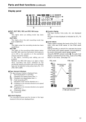
... lights when an editing mode has been selected. Using the METER selector button O, the audio level display is switched from the FULL mode to ON or the cassette is in the recording inhibit status (when the REC INH switch at the bottom front panel is selected, the levels of the PCM audio signals. Tape transport displays The tape transport status is to light or flash when recording...
... lights when an editing mode has been selected. Using the METER selector button O, the audio level display is switched from the FULL mode to ON or the cassette is in the recording inhibit status (when the REC INH switch at the bottom front panel is selected, the levels of the PCM audio signals. Tape transport displays The tape transport status is to light or flash when recording...
AJSD965 User Guide
Page 18
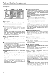
... termination switch to the power outlet. 2 DIGITAL AUDIO IN and OUT connectors These are the input and output connectors for digital audio signals that comply with the AES/EBU standards. Two remote control connectors are to be made to the OUT connector for each pair of input connectors. The digital audio signals which are the input connectors of the power cord supplied to this VTR, set ON or OFF is selected using setup menu No. 212 (MASTER PORT). 7 ENCODER REMOTE connector An external encoder remote controller...
... termination switch to the power outlet. 2 DIGITAL AUDIO IN and OUT connectors These are the input and output connectors for digital audio signals that comply with the AES/EBU standards. Two remote control connectors are to be made to the OUT connector for each pair of input connectors. The digital audio signals which are the input connectors of the power cord supplied to this VTR, set ON or OFF is selected using setup menu No. 212 (MASTER PORT). 7 ENCODER REMOTE connector An external encoder remote controller...
AJSD965 User Guide
Page 35
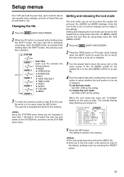
... SHIFT button, the previous user file is selected; To set , "LOCKED" flashes on the menu screen to No. 30 (MENU LOCK) for the system file or to be used, press the SET button. When the lock mode has been set the lock mode: Set 0001 (ON) as the setting. SETUP-MENU LOCKED NO.000-0005 2000 P-ROLL TIME 5s 001 LOCAL ENA ST&EJ 002 TAPE TIMER ±12h 003 REMAIN SEL OFF 004 SETUP NUMBER...
... SHIFT button, the previous user file is selected; To set , "LOCKED" flashes on the menu screen to No. 30 (MENU LOCK) for the system file or to be used, press the SET button. When the lock mode has been set the lock mode: Set 0001 (ON) as the setting. SETUP-MENU LOCKED NO.000-0005 2000 P-ROLL TIME 5s 001 LOCAL ENA ST&EJ 002 TAPE TIMER ±12h 003 REMAIN SEL OFF 004 SETUP NUMBER...
AJSD965 User Guide
Page 42
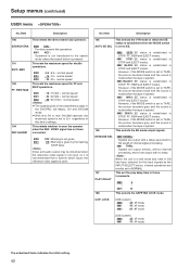
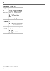
... CAPSTAN LOCK mode. REW MAX 104 REF ALARM 0000 DIAL : For direct search dial operations. 0001 KEY : Operation is not transferred to TAPE, the picture becomes black and the sound is muted when the tape is ejected. 0004 GRAY : EE status is in STOP, FF, REW and EJECT modes. However, if the MODE switch is set to warn the operator when the REF. Setup menus (continued) USER menu No...
... CAPSTAN LOCK mode. REW MAX 104 REF ALARM 0000 DIAL : For direct search dial operations. 0001 KEY : Operation is not transferred to TAPE, the picture becomes black and the sound is muted when the tape is ejected. 0004 GRAY : EE status is in STOP, FF, REW and EJECT modes. However, if the MODE switch is set to warn the operator when the REF. Setup menus (continued) USER menu No...
AJSD965 User Guide
Page 43
... mode concerned is selected as the setup menu item No. 105 (AUTO EE SEL) setting. OFreeze status complies with the preroll operation, and it automatically stops when it is frozen and output. This selects whether audio input switching using the INPUT SELECT button is to be enabled or disabled. 113 A IN SEL INH 0000 OFF : Video input switching using the INPUT SELECT button is enabled. 0001 ON : Video input switching using the INPUT SELECT button...
... mode concerned is selected as the setup menu item No. 105 (AUTO EE SEL) setting. OFreeze status complies with the preroll operation, and it automatically stops when it is frozen and output. This selects whether audio input switching using the INPUT SELECT button is to be enabled or disabled. 113 A IN SEL INH 0000 OFF : Video input switching using the INPUT SELECT button is enabled. 0001 ON : Video input switching using the INPUT SELECT button...
AJSD965 User Guide
Page 44
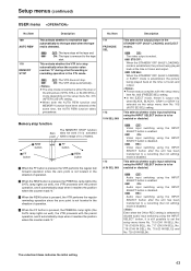
...setting. 44 OFF : Operation is to remain lighted or be turned off in the cassette out status. 0000 MODE1 : The EJECT lamp remains lit. 0001 MODE2 : The EJECT lamp goes off. This selects whether the EJECT lamp is enabled in the recording mode. Setup menus (continued) USER menu... No./Item Description 114 This selects whether to cause the REC INH lamp to flash or light up . 0001 FLASH : The lamp flashes. When the REC INH switch is set to the accidental erasure prevention status. 0000 LIGHT : The lamp lights up ...
...setting. 44 OFF : Operation is to remain lighted or be turned off in the cassette out status. 0000 MODE1 : The EJECT lamp remains lit. 0001 MODE2 : The EJECT lamp goes off. This selects whether the EJECT lamp is enabled in the recording mode. Setup menus (continued) USER menu... No./Item Description 114 This selects whether to cause the REC INH lamp to flash or light up . 0001 FLASH : The lamp flashes. When the REC INH switch is set to the accidental erasure prevention status. 0000 LIGHT : The lamp lights up ...
AJSD965 User Guide
Page 62
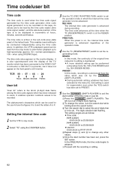
... "TC" using the time code alone. It enables operator numbers values to be conducted independently using the COUNTER button. 3 Use the TC (REC RUN/FREE RUN) switch to set , press the SET button. Setting the internal time code 1 Set the VTR to advance. 6 Proceed with the recording or editing. 62 The digits selected start number has been set the operation mode in the sub-code area (data area) of the operation mode. 4 Use the TC (REGEN/PRESET) switch to be recorded.
... "TC" using the time code alone. It enables operator numbers values to be conducted independently using the COUNTER button. 3 Use the TC (REC RUN/FREE RUN) switch to set , press the SET button. Setting the internal time code 1 Set the VTR to advance. 6 Proceed with the recording or editing. 62 The digits selected start number has been set the operation mode in the sub-code area (data area) of the operation mode. 4 Use the TC (REGEN/PRESET) switch to be recorded.
AJSD965 User Guide
Page 63
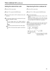
... the video signals from the VIDEO OUT 3/SDI OUT 3 connector. LTC must be selected with the video signal. Playback starts and the time code is automatically interpolated by the CTL signal. Time code/user bit (continued) Setting the external time code Reproducing the time code/user bit 1 Set the VTR to stop mode. 1 Set the VTR to stop mode. 2 Select "TC" using the COUNTER button. 2 Select "TC" or "UB" using the COUNTER button. 3 Set the TCG switch to EXT. (External time code selection...
... the video signals from the VIDEO OUT 3/SDI OUT 3 connector. LTC must be selected with the video signal. Playback starts and the time code is automatically interpolated by the CTL signal. Time code/user bit (continued) Setting the external time code Reproducing the time code/user bit 1 Set the VTR to stop mode. 1 Set the VTR to stop mode. 2 Select "TC" using the COUNTER button. 2 Select "TC" or "UB" using the COUNTER button. 3 Set the TCG switch to EXT. (External time code selection...
AJSD965 User Guide
Page 71
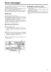
... button. DIAG menu $ "WARNING" information display OA warning message is displayed. The DIAG menu screen is displayed on the monitor, and the message is displayed on the counter display. 2 Each time the search button is connected to the VIDEO OUT 3/SDI OUT 3 connector on the counter display. Error messages When a warning occurs in the unit, the error number flashes on . 3 Press the DIAG button again to return to the original display. 2 ON OFF POWER 2X REMOTE DVCPRO...
... button. DIAG menu $ "WARNING" information display OA warning message is displayed. The DIAG menu screen is displayed on the monitor, and the message is displayed on the counter display. 2 Each time the search button is connected to the VIDEO OUT 3/SDI OUT 3 connector on the counter display. Error messages When a warning occurs in the unit, the error number flashes on . 3 Press the DIAG button again to return to the original display. 2 ON OFF POWER 2X REMOTE DVCPRO...


