

WVCL920A User Guide
Page 1
Color CCTV Cameras Operating Instructions Model No. WV-CL920A WV-CL924 WV-CL924A (Lens : option) Before attempting to connect or operate this product, please read these instructions carefully and save this manual for future use.
Color CCTV Cameras Operating Instructions Model No. WV-CL920A WV-CL924 WV-CL924A (Lens : option) Before attempting to connect or operate this product, please read these instructions carefully and save this manual for future use.

WVCL920A User Guide
Page 5
CONTENTS IMPORTANT SAFETY INSTRUCTIONS ...3 PREFACE ...6 FEATURES ...7 PRECAUTIONS ...8 MAJOR OPERATING CONTROLS AND THEIR FUNCTIONS 9 CONNECTIONS ...12 FOCUS OR FLANGE-BACK ADJUSTMENT ...16 INSTALLATION OF CAMERA ...17 SETUP ...18 1. SETUP OPERATION ...21 SETTING PROCEDURES ...23 PREVENTION OF BLOOMING AND SMEAR ...42 SPECIFICATIONS ...42 STANDARD ACCESSORIES ...44 OPTIONAL ACCESSORIES ...45 -5- CAMERA SETUP MENU ...18 2.
CONTENTS IMPORTANT SAFETY INSTRUCTIONS ...3 PREFACE ...6 FEATURES ...7 PRECAUTIONS ...8 MAJOR OPERATING CONTROLS AND THEIR FUNCTIONS 9 CONNECTIONS ...12 FOCUS OR FLANGE-BACK ADJUSTMENT ...16 INSTALLATION OF CAMERA ...17 SETUP ...18 1. SETUP OPERATION ...21 SETTING PROCEDURES ...23 PREVENTION OF BLOOMING AND SMEAR ...42 SPECIFICATIONS ...42 STANDARD ACCESSORIES ...44 OPTIONAL ACCESSORIES ...45 -5- CAMERA SETUP MENU ...18 2.

WVCL920A User Guide
Page 6
PREFACE Panasonic's WV-CL920A (WV-CL924A) series digital color camera introduces a new level of high picture quality and high resolution through the use of a 1/2-inch frame interline transfer CCD image sensor having 768 horizontal pixels (picture elements), and digital signal processing LSI's. This model offers cutting-edge technology for advanced video surveillance. -6-
PREFACE Panasonic's WV-CL920A (WV-CL924A) series digital color camera introduces a new level of high picture quality and high resolution through the use of a 1/2-inch frame interline transfer CCD image sensor having 768 horizontal pixels (picture elements), and digital signal processing LSI's. This model offers cutting-edge technology for advanced video surveillance. -6-

WVCL920A User Guide
Page 7
... following functions are built in Digital Motion Detector 10. Selectable electronic sensitivity enhancing modes including: AUTO, MANUAL and OFF 9. Auto Black/White mode enables the camera to switch between C/L and B/W in response to -noise ratio of Electronic Light Control (ELC) function. 8. Signal-to input lights. -7- FEATURES 1.
... following functions are built in Digital Motion Detector 10. Selectable electronic sensitivity enhancing modes including: AUTO, MANUAL and OFF 9. Auto Black/White mode enables the camera to switch between C/L and B/W in response to -noise ratio of Electronic Light Control (ELC) function. 8. Signal-to input lights. -7- FEATURES 1.

WVCL920A User Guide
Page 8
... may be damaged by qualified service personnel or system installers. 2. To prevent electric shock, do not remove screws or covers. Do not abuse the camera. Use the camera under conditions where temperature is between -10 °C - +50 °C (14 °F - 122 °F), and humidity is 120 V AC 60 Hz for WV-CL920A... WV-CL924A. Afterwards, wipe off the remained part of the detergent in use a UL listed cable (VW-1, style 1007) for servicing. 3. Do not aim the camera at the sun or other extremely bright objects. Do not use a mild detergent and wipe gently. Do not operate the...
... may be damaged by qualified service personnel or system installers. 2. To prevent electric shock, do not remove screws or covers. Do not abuse the camera. Use the camera under conditions where temperature is between -10 °C - +50 °C (14 °F - 122 °F), and humidity is 120 V AC 60 Hz for WV-CL920A... WV-CL924A. Afterwards, wipe off the remained part of the detergent in use a UL listed cable (VW-1, style 1007) for servicing. 3. Do not aim the camera at the sun or other extremely bright objects. Do not use a mild detergent and wipe gently. Do not operate the...
WVCL920A User Guide
Page 10
.... In case of using a C-mount lens, adjust it with the VIDEO IN connector of the monitor. -10- e Lens (Option) r Focus Fixing Screw (LOCK) t Camera Mounting Screw Hole This hole is used to adjust the back focal length or picture focus. Rotate this switch to Hi-Z when a gen-lock video... used to adjust some levels. It is used to move the cursor upward. w Flange-back Adjusting Ring (FB) This ring is used to mount the camera onto a mounting bracket. y Down Button (K) This button is also used to select the mode and can be used to adjust some levels. YFE4191J100). o...
.... In case of using a C-mount lens, adjust it with the VIDEO IN connector of the monitor. -10- e Lens (Option) r Focus Fixing Screw (LOCK) t Camera Mounting Screw Hole This hole is used to adjust the back focal length or picture focus. Rotate this switch to Hi-Z when a gen-lock video... used to adjust some levels. It is used to move the cursor upward. w Flange-back Adjusting Ring (FB) This ring is used to mount the camera onto a mounting bracket. y Down Button (K) This button is also used to select the mode and can be used to adjust some levels. YFE4191J100). o...
WVCL920A User Guide
Page 11
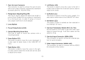
.... !7 AC/DC Compatible Input Terminal (DC 12V IN/AC 24V IN, GND) This terminal is supplied from a 24 V AC power source. -11- When the camera detects motion, the alarm output signal is supplied to the connected external device (Open collector output: 16 V DC, 100 mA max). !5 Day/Night Input Terminal... (DAY/NIGHT IN/GND) This terminal is used for connecting the camera to an external day/night detecting sensor. !6 AC Inlet Socket Plug the power cord (supplied as a standard accessory) into this socket and connect it to...
.... !7 AC/DC Compatible Input Terminal (DC 12V IN/AC 24V IN, GND) This terminal is supplied from a 24 V AC power source. -11- When the camera detects motion, the alarm output signal is supplied to the connected external device (Open collector output: 16 V DC, 100 mA max). !5 Day/Night Input Terminal... (DAY/NIGHT IN/GND) This terminal is used for connecting the camera to an external day/night detecting sensor. !6 AC Inlet Socket Plug the power cord (supplied as a standard accessory) into this socket and connect it to...

WVCL920A User Guide
Page 12
...) Resistance Ω/m 0.078 0.050 0.030 0.018 Resistance Ω/ft 0.026 0.017 0.010 0.006 You can be pulled off the camera when the camera pans or tilts. Connect the AC power cord to the AC/DC compatible input terminal on the rear panel of power supply R: Resistance (&#...), see table L: Cable length (m) (ft) I: Current consumption (A), see specifications -12- The WV-CL924A has an AC/DC compatible input terminal. The camera detects the power source automatically. 1. 12 V DC Power Supply Connect the power cord to a 120 V AC 60 Hz outlet. If the cable is supplied...
...) Resistance Ω/m 0.078 0.050 0.030 0.018 Resistance Ω/ft 0.026 0.017 0.010 0.006 You can be pulled off the camera when the camera pans or tilts. Connect the AC power cord to the AC/DC compatible input terminal on the rear panel of power supply R: Resistance (&#...), see table L: Cable length (m) (ft) I: Current consumption (A), see specifications -12- The WV-CL924A has an AC/DC compatible input terminal. The camera detects the power source automatically. 1. 12 V DC Power Supply Connect the power cord to a 120 V AC 60 Hz outlet. If the cable is supplied...

WVCL920A User Guide
Page 13
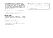
... 100 mA maximum (Active) Note: Use a relay if the voltage or current of Cable (Approx.) (ft) 314 495 842 1 403 Video Cable 1. Type of the camera. 2. 2. 24 V AC Power Supply Connect the power cable to the DAY/NIGHT IN terminal. • Color/black-and-white input terminal with a capacity of 16... the Day/Night function, set BW mode to the ALARM terminal. • The alarm output terminal is an open collector terminal with a capacity of the camera. Connect an external device such as a buzzer or lamp to EXT on the rear panel of 5 V DC pull-up input, 0.2 mA or more. It is...
... 100 mA maximum (Active) Note: Use a relay if the voltage or current of Cable (Approx.) (ft) 314 495 842 1 403 Video Cable 1. Type of the camera. 2. 2. 24 V AC Power Supply Connect the power cable to the DAY/NIGHT IN terminal. • Color/black-and-white input terminal with a capacity of 16... the Day/Night function, set BW mode to the ALARM terminal. • The alarm output terminal is an open collector terminal with a capacity of the camera. Connect an external device such as a buzzer or lamp to EXT on the rear panel of 5 V DC pull-up input, 0.2 mA or more. It is...
WVCL920A User Guide
Page 15
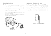
...(5/32") Caution for Mounting the Lens The lens mount should be secured by turning it clockwise on the side of the camera. If the lens is not at the rear of the camera. 2. The protrusion at the end, the inner glass or CCD image sensor may be damaged. 1. In case of the... rotate the flangeback adjusting ring counterclockwise until it stops. CS-mount: Less than 450 g (0.99 lbs). If the ring is heavier, both the lens and camera should be a CS-mount (1"-32UN). Mounting the Lens Caution: Before you mount the lens, loosen the fixing screw on the side of a C-mount, it should...
...(5/32") Caution for Mounting the Lens The lens mount should be secured by turning it clockwise on the side of the camera. If the lens is not at the rear of the camera. 2. The protrusion at the end, the inner glass or CCD image sensor may be damaged. 1. In case of the... rotate the flangeback adjusting ring counterclockwise until it stops. CS-mount: Less than 450 g (0.99 lbs). If the ring is heavier, both the lens and camera should be a CS-mount (1"-32UN). Mounting the Lens Caution: Before you mount the lens, loosen the fixing screw on the side of a C-mount, it should...
WVCL920A User Guide
Page 16
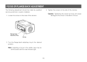
Flange-back Adjusting Ring Screw 2. Note: Adjusting a focus in the visible rays may be made by force will cause damage to the desired position. Tighten the screws on the side of the camera. Turn the flange-back adjusting ring to the screw or deviation of focus. Loosen the screw on the side of the camera. 3. Caution: Tightening the screw by qualified service personnel or system installers. 1. FOCUS OR FLANGE-BACK ADJUSTMENT The following adjustment should be soft-focused with the near-infrared light. -16-
Flange-back Adjusting Ring Screw 2. Note: Adjusting a focus in the visible rays may be made by force will cause damage to the desired position. Tighten the screws on the side of the camera. Turn the flange-back adjusting ring to the screw or deviation of focus. Loosen the screw on the side of the camera. 3. Caution: Tightening the screw by qualified service personnel or system installers. 1. FOCUS OR FLANGE-BACK ADJUSTMENT The following adjustment should be soft-focused with the near-infrared light. -16-
WVCL920A User Guide
Page 17
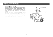
Use the two original screws to attach the mount adapter to the top as shown in the diagram, then mount the camera on the mounting bracket. Using shorter ones may cause the camera to fall down, and using longer ones may damage the inside of the camera by removing the two fixing screws. Attach the mount adapter to the camera. Fixing Screws Mount Adapter -17- INSTALLATION OF CAMERA • Mounting from the top Remove the mount adapter from the bottom of the camera.
Use the two original screws to attach the mount adapter to the top as shown in the diagram, then mount the camera on the mounting bracket. Using shorter ones may cause the camera to fall down, and using longer ones may damage the inside of the camera by removing the two fixing screws. Attach the mount adapter to the camera. Fixing Screws Mount Adapter -17- INSTALLATION OF CAMERA • Mounting from the top Remove the mount adapter from the bottom of the camera.

WVCL920A User Guide
Page 18
...ALC ELC Shutter Speed AGC ON(DNR-H)/ON(DNR-M)/ ON(DNR-L)/OFF Electronic Sensitivity Enhancement OFF/AUTO/FIX SYNC INT/LL Camera ID Editing Camera ID Display Position PRESET OFF PRESET ON (Back Light Compensation) Peak Mode Selection PRESET OFF PRESET ON (Back Light Compensation)...Manual Mask Area Selection Manual Level Selection Peak Mode Selection Manual Mask Area Selection Manual Level Selection Peak Mode Selection -18- CAMERA SETUP MENU This camera utilizes a user setup menu that form a tree type structure. The setup menu contains various items that is displayed on-...
...ALC ELC Shutter Speed AGC ON(DNR-H)/ON(DNR-M)/ ON(DNR-L)/OFF Electronic Sensitivity Enhancement OFF/AUTO/FIX SYNC INT/LL Camera ID Editing Camera ID Display Position PRESET OFF PRESET ON (Back Light Compensation) Peak Mode Selection PRESET OFF PRESET ON (Back Light Compensation)...Manual Mask Area Selection Manual Level Selection Peak Mode Selection Manual Mask Area Selection Manual Level Selection Peak Mode Selection -18- CAMERA SETUP MENU This camera utilizes a user setup menu that form a tree type structure. The setup menu contains various items that is displayed on-...
WVCL920A User Guide
Page 19
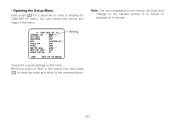
... the Setup Menu Hold down I to close and change to the camera picture if no button is pressed for 2 seconds or more to the camera picture. You can confirm the current settings on the menu. ** CAM SET UP ** ↵↵ CAMERA ID OFF ALC/ELC ALC SHUTTER OFF AGC ON(DNR-H) SENS UP...
... the Setup Menu Hold down I to close and change to the camera picture if no button is pressed for 2 seconds or more to the camera picture. You can confirm the current settings on the menu. ** CAM SET UP ** ↵↵ CAMERA ID OFF ALC/ELC ALC SHUTTER OFF AGC ON(DNR-H) SENS UP...
WVCL920A User Guide
Page 20
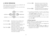
... a user setup menu (CAM SET UP) that the setup menu is not displayed (a camera picture is pressed. Left Button Set Button Up Button Right Button Down Button Up Button (J): Moves the cursor upwards. Use this button to select an ...
... a user setup menu (CAM SET UP) that the setup menu is not displayed (a camera picture is pressed. Left Button Set Button Up Button Right Button Down Button Up Button (J): Moves the cursor upwards. Use this button to select an ...
WVCL920A User Guide
Page 21
...off. -22- These values remain valid until new values are saved in the bottom line of the camera is to SET UP ENABLE. Move the cursor to END, then to the item(s) you cannot change . ** ...CAM SET UP ** ↵↵ CAMERA ID OFF ALC/ELC ALC SHUTTER OFF AGC ON(DNR-H) SENS UP OFF SYNC INT ↵ WHITE BAL... ATW1 MOTION DET OFF LENS DRIVE DC END SET UP DISABLE ↵ ** CAM SET UP ** ↵↵ CAMERA ID OFF ALC/ELC ALC SHUTTER OFF AGC ON(DNR-H) SENS UP OFF SYNC INT ↵ WHITE BAL ATW1 MOTION...
...off. -22- These values remain valid until new values are saved in the bottom line of the camera is to SET UP ENABLE. Move the cursor to END, then to the item(s) you cannot change . ** ...CAM SET UP ** ↵↵ CAMERA ID OFF ALC/ELC ALC SHUTTER OFF AGC ON(DNR-H) SENS UP OFF SYNC INT ↵ WHITE BAL... ATW1 MOTION DET OFF LENS DRIVE DC END SET UP DISABLE ↵ ** CAM SET UP ** ↵↵ CAMERA ID OFF ALC/ELC ALC SHUTTER OFF AGC ON(DNR-H) SENS UP OFF SYNC INT ↵ WHITE BAL ATW1 MOTION...
WVCL920A User Guide
Page 22
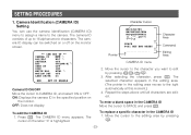
... a blank space in the editing area moves to edit by pressing K. -23- Press I . ON: Displays the camera ID in the CAMERA ID 1. The CAMERA ID menu appears. OFF: Does not display. Character Cursor Pointer 0123456789 ABCDEFGHIJKLM NOPQRSTUVWXYZ SPACE POSI RET END RESET Character Area Command... Editing Area CAMERA ID menu 2. Move the cursor to the character you want to the right automatically at this moment.) 4. To replace ...
... a blank space in the editing area moves to edit by pressing K. -23- Press I . ON: Displays the camera ID in the CAMERA ID 1. The CAMERA ID menu appears. OFF: Does not display. Character Cursor Pointer 0123456789 ABCDEFGHIJKLM NOPQRSTUVWXYZ SPACE POSI RET END RESET Character Area Command... Editing Area CAMERA ID menu 2. Move the cursor to the character you want to the right automatically at this moment.) 4. To replace ...

WVCL920A User Guide
Page 23
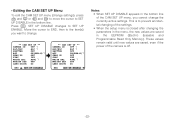
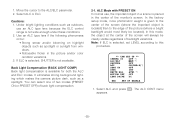
...of L/ M/J/K is highlighted. ELC: Select this mode when a fixed iris lens or manual iris lens is used with this camera. ↵ ** CAM SET UP ** ↵↵ CAMERA ID OFF ALC/ELC ALC SHUTTER OFF AGC ON(DNR-H) SENS UP OFF SYNC INT ↵ WHITE BAL ATW1 MOTION DET ... DC END SET UP ENABLE -24- 2. Press I to POSI, and press I. Move the cursor to determine the CAMERA ID. Move the CAMERA ID to RESET and press I to the previous CAMERA ID menu. To erase all characters in the editing area disappear. Press I . Highlighted WV-CL920A 2. The display shown...
...of L/ M/J/K is highlighted. ELC: Select this mode when a fixed iris lens or manual iris lens is used with this camera. ↵ ** CAM SET UP ** ↵↵ CAMERA ID OFF ALC/ELC ALC SHUTTER OFF AGC ON(DNR-H) SENS UP OFF SYNC INT ↵ WHITE BAL ATW1 MOTION DET ... DC END SET UP ENABLE -24- 2. Press I to POSI, and press I. Move the cursor to determine the CAMERA ID. Move the CAMERA ID to RESET and press I to the previous CAMERA ID menu. To erase all characters in the editing area disappear. Press I . Highlighted WV-CL920A 2. The display shown...
WVCL920A User Guide
Page 24
... control range is placed in the picture and/or color rendition variations. 3. Select ALC and press I. It eliminates strong background lighting which makes the camera picture dark, such as a spotlight. The ALC CONT menu appears. -25- Cautions: 1. In this procedure. ↵ ** CAM SET UP ** ↵↵...; CAMERA ID OFF ALC/ELC ALC SHUTTER OFF AGC ON(DNR-H) SENS UP OFF SYNC INT ↵ WHITE BAL ATW1 MOTION DET OFF LENS DRIVE DC ...
... control range is placed in the picture and/or color rendition variations. 3. Select ALC and press I. It eliminates strong background lighting which makes the camera picture dark, such as a spotlight. The ALC CONT menu appears. -25- Cautions: 1. In this procedure. ↵ ** CAM SET UP ** ↵↵...; CAMERA ID OFF ALC/ELC ALC SHUTTER OFF AGC ON(DNR-H) SENS UP OFF SYNC INT ↵ WHITE BAL ATW1 MOTION DET OFF LENS DRIVE DC ...
WVCL920A User Guide
Page 26
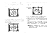
... the cursor to END and press I . Move the cursor to RET and press I to return to the CAM SET UP menu. (To return to the camera picture, move the cursor to the area where backlight is blinking in ELC mode. -27-
... the cursor to END and press I . Move the cursor to RET and press I to return to the CAM SET UP menu. (To return to the camera picture, move the cursor to the area where backlight is blinking in ELC mode. -27-


