
Manual
Page 2
...Jack Connection 12 VIDEO Input/Output Connection 13 Connection Diagram 14 Connecting the Power Cord 14 Key Finder 16 • Remote Controller Before Using This Product 17 About This Product 17 About This Manual 18 To Ensure Safe Driving 18 Resetting the Microprocessor 19 Precaution 19 In ...Entering the Detailed Setting Menu 27 • Detailed Setting Menu Functions Tuner Operation 29 Local Seek Tuning (LOCAL 29 Best Stations Memory (BSM 30 Using the RDS Functions 31 What is RDS 31 Frequency Display ON/OFF 31 • Program Service Name • PTY Information AF Function (AF...
...Jack Connection 12 VIDEO Input/Output Connection 13 Connection Diagram 14 Connecting the Power Cord 14 Key Finder 16 • Remote Controller Before Using This Product 17 About This Product 17 About This Manual 18 To Ensure Safe Driving 18 Resetting the Microprocessor 19 Precaution 19 In ...Entering the Detailed Setting Menu 27 • Detailed Setting Menu Functions Tuner Operation 29 Local Seek Tuning (LOCAL 29 Best Stations Memory (BSM 30 Using the RDS Functions 31 What is RDS 31 Frequency Display ON/OFF 31 • Program Service Name • PTY Information AF Function (AF...

Manual
Page 3
...Entering the Audio Menu 53 Balance Adjustment (FADER/BALANCE) ..... 54 Bass/Middle/Treble Adjustment (BASS/MID/TREBLE 55 Loudness Adjustment (LOUDNESS 56 Using a Subwoofer 56 • Subwoofer Output (SUBW.1) • Subwoofer Setting Adjustment (SUBW.2) Front Image Enhancer Function (FIE 58 Source Level ... • Setting the PGM Button • Using the PGM Button Using the AUX Source 69 • Selecting the AUX Source • AUX Title Input Using the Speaker Input Source 70 Selecting the Picture (Front Display 70 Using the Rear Display 71 Volume Attenuator 71 Muting Function...
...Entering the Audio Menu 53 Balance Adjustment (FADER/BALANCE) ..... 54 Bass/Middle/Treble Adjustment (BASS/MID/TREBLE 55 Loudness Adjustment (LOUDNESS 56 Using a Subwoofer 56 • Subwoofer Output (SUBW.1) • Subwoofer Setting Adjustment (SUBW.2) Front Image Enhancer Function (FIE 58 Source Level ... • Setting the PGM Button • Using the PGM Button Using the AUX Source 69 • Selecting the AUX Source • AUX Title Input Using the Speaker Input Source 70 Selecting the Picture (Front Display 70 Using the Rear Display 71 Volume Attenuator 71 Muting Function...

Manual
Page 4
Route all connected up properly, and the unit and the system work properly. • Use only the parts included with the unit to ensure proper installation. The use of unauthorized parts can cause malfunctions. • Consult with Velcro Tape • Thoroughly wipe off the surface before affixing the velcro tape. Do not drill...
Route all connected up properly, and the unit and the system work properly. • Use only the parts included with the unit to ensure proper installation. The use of unauthorized parts can cause malfunctions. • Consult with Velcro Tape • Thoroughly wipe off the surface before affixing the velcro tape. Do not drill...

Manual
Page 5
... install the remote control unit to the passenger's side - Fitting horizontally Fitting vertically Installation Using Only the Mounting Base • To avoid it clicks into place. not the driver's side. • Before using double-sided tape, clean off any dirt on the surface to which the doublesided tape ...is slanting upwards at an angle when fitted. Passenger seat Mounting Base Double-sided tape Not used Used • Install the mounting base so that the ...
... install the remote control unit to the passenger's side - Fitting horizontally Fitting vertically Installation Using Only the Mounting Base • To avoid it clicks into place. not the driver's side. • Before using double-sided tape, clean off any dirt on the surface to which the doublesided tape ...is slanting upwards at an angle when fitted. Passenger seat Mounting Base Double-sided tape Not used Used • Install the mounting base so that the ...
Manual
Page 6
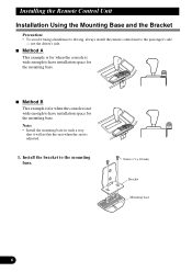
Installation Using the Mounting Base and the Bracket • To avoid it will not hit the seat when the seat is not wide enough to the passenger's side - Screws (3 10 mm) Bracket Mounting base Method A This example is for when the console is wide enough to have installation space for the mounting base. • Install the mounting base in such a way that it being a hindrance to driving, always install the remote control unit to have installation space for the mounting base. Method B This example is for when the console is adjusted. not the driver's side.
Installation Using the Mounting Base and the Bracket • To avoid it will not hit the seat when the seat is not wide enough to the passenger's side - Screws (3 10 mm) Bracket Mounting base Method A This example is for when the console is wide enough to have installation space for the mounting base. • Install the mounting base in such a way that it being a hindrance to driving, always install the remote control unit to have installation space for the mounting base. Method B This example is for when the console is adjusted. not the driver's side.

Manual
Page 7
• • Before using double-sided tape, clean off any of the cars operating systems (such as the fuel line, brake lines, electrical wiring, etc.). Passenger seat • • Before drilling any mounting holes, confirm that the screws will not interfere with any dirt on the surface to which the doublesided tape is to be attached. Passenger seat Double-sided tape Drill holes 2 - 2.5 mm in diameter Screws (4 12 mm)
• • Before using double-sided tape, clean off any of the cars operating systems (such as the fuel line, brake lines, electrical wiring, etc.). Passenger seat • • Before drilling any mounting holes, confirm that the screws will not interfere with any dirt on the surface to which the doublesided tape is to be attached. Passenger seat Double-sided tape Drill holes 2 - 2.5 mm in diameter Screws (4 12 mm)

Manual
Page 8
... not route wiring in a vehicle that does not have the same function. This will be exceeded, causing overheating. • When replacing fuse, be sure to use only fuse of the rating prescribed on the ignition switch, the red lead of the unit should . • Never feed power to other than those... current drain and malfunction. • To prevent incorrect connection, the input side of the IP-BUS connector is blue, and the output side is being used with this system, be sure not to connect the blue/white lead to the amp's power terminal. Please ground this unit is a danger of the...
... not route wiring in a vehicle that does not have the same function. This will be exceeded, causing overheating. • When replacing fuse, be sure to use only fuse of the rating prescribed on the ignition switch, the red lead of the unit should . • Never feed power to other than those... current drain and malfunction. • To prevent incorrect connection, the input side of the IP-BUS connector is blue, and the output side is being used with this system, be sure not to connect the blue/white lead to the amp's power terminal. Please ground this unit is a danger of the...
Manual
Page 9
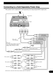
... separately) Power amp (sold separately) Power amp (sold separately). Connecting to a Sold Separately Power Amp This product can be connected to a sold separately power amp using a different amp (sold separately) System remote control System remote control System remote control Front speaker Front speaker Rear speaker Subwoofer Perform these connections when...
... separately) Power amp (sold separately) Power amp (sold separately). Connecting to a Sold Separately Power Amp This product can be connected to a sold separately power amp using a different amp (sold separately) System remote control System remote control System remote control Front speaker Front speaker Rear speaker Subwoofer Perform these connections when...
Manual
Page 12
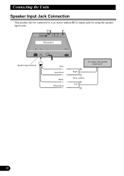
This product Speaker input terminal Gray Gray/black White White/black Car stereo with speaker output jacks. Right Front speaker Left Speaker Input Jack Connection This product also be connected to a car stereo without RCA output jacks by using the speaker input jacks.
This product Speaker input terminal Gray Gray/black White White/black Car stereo with speaker output jacks. Right Front speaker Left Speaker Input Jack Connection This product also be connected to a car stereo without RCA output jacks by using the speaker input jacks.

Manual
Page 13
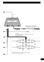
... (White) Yellow To audio outputs To video output RCA cables (sold separately) External video component (sold separately) VIDEO Input/Output Connection It is possible to use up to two external video components by connecting them to Rear Display output, you can also watch the external video component's picture.
... (White) Yellow To audio outputs To video output RCA cables (sold separately) External video component (sold separately) VIDEO Input/Output Connection It is possible to use up to two external video components by connecting them to Rear Display output, you can also watch the external video component's picture.

Manual
Page 14
...Clamp the parking brake switch power supply side lead. Fuse resistor Clamp firmly with power regardless of ignition switch position. Yellow/black If you use a cellular telephone, connect it via the Audio Mute lead on the vehicle model. Yellow To terminal always supplied with needle-nosed pliers....on the cellular telephone. Fuse resistor Orange To lighting switch terminal. Connecting the Power Cord Parking brake switch Power supply side Blue/yellow Used to the power supply side of the parking brake switch. If not, keep the Audio Mute lead free of the parking brake. Black...
...Clamp the parking brake switch power supply side lead. Fuse resistor Clamp firmly with power regardless of ignition switch position. Yellow/black If you use a cellular telephone, connect it via the Audio Mute lead on the vehicle model. Yellow To terminal always supplied with needle-nosed pliers....on the cellular telephone. Fuse resistor Orange To lighting switch terminal. Connecting the Power Cord Parking brake switch Power supply side Blue/yellow Used to the power supply side of the parking brake switch. If not, keep the Audio Mute lead free of the parking brake. Black...
Manual
Page 15
This product Antenna jack Antenna extension cable (supplied) If the antenna from the vehicle does not reach the Antenna jack, use this cable. Blue/white To system control terminal of the power amp or Auto-antenna relay control terminal. (Max. 300 mA 12 V DC) Front speaker Left Rear speaker White Gray White/ black Green Gray/black Left (White) Green/ black Violet/black With a 2 speaker system, do not connect anything to the speaker leads that are not connected to speakers. Front speaker Right Rear speaker
This product Antenna jack Antenna extension cable (supplied) If the antenna from the vehicle does not reach the Antenna jack, use this cable. Blue/white To system control terminal of the power amp or Auto-antenna relay control terminal. (Max. 300 mA 12 V DC) Front speaker Left Rear speaker White Gray White/ black Green Gray/black Left (White) Green/ black Violet/black With a 2 speaker system, do not connect anything to the speaker leads that are not connected to speakers. Front speaker Right Rear speaker

Manual
Page 17
... only in other operations. Key Guidance Indicators eg: Function Menu eg: Audio Menu • When "ON" and "OFF" are lit, you can use in improper reception. These light to switch functions ON/OFF, switch repeat selections, and perform other areas may result in Western Europe, Asia, the Middle... East, Africa and Oceania. It is lit, you can use . This product's display features Key Guidance Indicators. When you're in the Function Menu or Audio Menu, they also make it easy to see...
... only in other operations. Key Guidance Indicators eg: Function Menu eg: Audio Menu • When "ON" and "OFF" are lit, you can use in improper reception. These light to switch functions ON/OFF, switch repeat selections, and perform other areas may result in Western Europe, Asia, the Middle... East, Africa and Oceania. It is lit, you can use . This product's display features Key Guidance Indicators. When you're in the Function Menu or Audio Menu, they also make it easy to see...

Manual
Page 18
...yourself with the functions and their potential and to maximize your vehicle and engaged the parking brake, the system may occur when: - To use , but many are not self-explanatory. We recommend that you have stopped your listening enjoyment. This may ignore this product. The ignition ... manual is in other sections. To Ensure Safe Driving To ensure safe vehicle operation, complicated functions are selected while driving, "YOU CANNOT USE THIS FUNCTION WHILE DRIVING" is engaged. About This Manual This product features a number of the parking brake cannot be assumed that the system...
...yourself with the functions and their potential and to maximize your vehicle and engaged the parking brake, the system may occur when: - To use , but many are not self-explanatory. We recommend that you have stopped your listening enjoyment. This may ignore this product. The ignition ... manual is in other sections. To Ensure Safe Driving To ensure safe vehicle operation, complicated functions are selected while driving, "YOU CANNOT USE THIS FUNCTION WHILE DRIVING" is engaged. About This Manual This product features a number of the parking brake cannot be assumed that the system...

Manual
Page 19
.... Resetting the Microprocessor The microprocessor must be reset under the following conditions: • When using this product for the first time after installation. • When the machine fails to operate properly, contact your dealer or nearest authorized PIONEER Service Station. In Case of Trouble Should this product fail to operate properly. •...
.... Resetting the Microprocessor The microprocessor must be reset under the following conditions: • When using this product for the first time after installation. • When the machine fails to operate properly, contact your dealer or nearest authorized PIONEER Service Station. In Case of Trouble Should this product fail to operate properly. •...

Manual
Page 20
This product is not in use, attach it may become jammed under the brake or accelerator pedal. Batteries • Use only AAA or IEC R03 1.5 V batteries. • Remove the batteries if the remote controller is not used for a month or longer. • Do not attempt to recharge the supplied batteries. • Do not mix... new and used batteries. • In the event of the signal reception on the color display (sold separately) to operate. • When the controller is equipped with a remote ...
This product is not in use, attach it may become jammed under the brake or accelerator pedal. Batteries • Use only AAA or IEC R03 1.5 V batteries. • Remove the batteries if the remote controller is not used for a month or longer. • Do not attempt to recharge the supplied batteries. • Do not mix... new and used batteries. • In the event of the signal reception on the color display (sold separately) to operate. • When the controller is equipped with a remote ...
Manual
Page 23
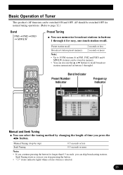
... 0.5 seconds, you stop pressing the button. • " " stereo indicator lights when a stereo station is selected. Basic Operation of Tuner This product's AF function can also use the or buttons to recall broadcast stations memorized in buttons 1 through 6. Seek Tuning starts as soon as you can skip broadcasting stations. Band Indicator Preset...
... 0.5 seconds, you stop pressing the button. • " " stereo indicator lights when a stereo station is selected. Basic Operation of Tuner This product's AF function can also use the or buttons to recall broadcast stations memorized in buttons 1 through 6. Seek Tuning starts as soon as you can skip broadcasting stations. Band Indicator Preset...

Manual
Page 24
... error message such as verifying the presence of Multi-CD Player This product can control a multi-CD player. (With certain old type multi-CD players, using a multiple connection adapter lets you connect multiple units which you can control with this product.) Disc Number Search (for 6-Disc, 12-Disc types) Disc Search...
... error message such as verifying the presence of Multi-CD Player This product can control a multi-CD player. (With certain old type multi-CD players, using a multiple connection adapter lets you connect multiple units which you can control with this product.) Disc Number Search (for 6-Disc, 12-Disc types) Disc Search...
Manual
Page 25
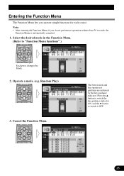
Each press changes the Mode ... Press the button to switch the key guidance indicator ON, and the button to switch it performs are indicated by the key guidance indicator. The button used and the operation it OFF. Entering the Function Menu The Function Menu lets you operate simple functions for each source. • After entering the Function Menu, if you do not perform an operation within about 30 seconds, the Function Menu is automatically canceled.
Each press changes the Mode ... Press the button to switch the key guidance indicator ON, and the button to switch it performs are indicated by the key guidance indicator. The button used and the operation it OFF. Entering the Function Menu The Function Menu lets you operate simple functions for each source. • After entering the Function Menu, if you do not perform an operation within about 30 seconds, the Function Menu is automatically canceled.
Manual
Page 26
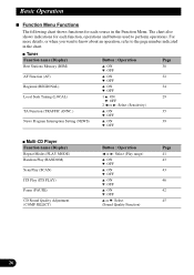
...) Function Menu Functions The following chart shows functions for each source in the chart. The chart also shows indications for each function, operations and buttons used to the page number indicated in the Function Menu. For more details, or when you want to know about an operation, refer to perform operations...
...) Function Menu Functions The following chart shows functions for each source in the chart. The chart also shows indications for each function, operations and buttons used to the page number indicated in the Function Menu. For more details, or when you want to know about an operation, refer to perform operations...

