Operation Manual
Page 48
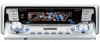
... EQ is completed in about six minutes. # To stop auto TA and EQ, press any buttons other than BAND. # To cancel auto TA and EQ part way through, press BAND. 11 When auto TA and EQ is completed, Complete is turned on, turn it off. Noise from the speakers, and auto...
... EQ is completed in about six minutes. # To stop auto TA and EQ, press any buttons other than BAND. # To cancel auto TA and EQ part way through, press BAND. 11 When auto TA and EQ is completed, Complete is turned on, turn it off. Noise from the speakers, and auto...
Service Manual
Page 3
...of the symbols, be sure to the regulations governing the product (safety, radio and noise, and other parts requiring cleaning, proper cleaning should be made securely. D E F DEH-P9600MP/XN/EW 3 5 6 7 8 Replaced only with the same or equivalent type recommended by the appropriate ...amount.For replacement parts or tools, the prescribed ones should be caused during servicing by following the instructions in ...
...of the symbols, be sure to the regulations governing the product (safety, radio and noise, and other parts requiring cleaning, proper cleaning should be made securely. D E F DEH-P9600MP/XN/EW 3 5 6 7 8 Replaced only with the same or equivalent type recommended by the appropriate ...amount.For replacement parts or tools, the prescribed ones should be caused during servicing by following the instructions in ...
Service Manual
Page 4
... 5. GENERAL INFORMATION ...64 7.1 DIAGNOSIS ...64 7.1.1 DISASSEMBLY ...64 7.1.2 CONNECTOR FUNCTION DESCRIPTION 72 7.2 PARTS...73 7.2.1 IC ...73 7.2.2 DISPLAY ...87 7.3 OPERATIONAL FLOW CHART ...88 7.4 CLEANING...89 D 8. EXPLODED VIEWS AND PARTS LIST ...8 2.1 PACKING ...8 2.2 EXTERIOR(1) ...10 2.3 EXTERIOR(2) ...12 2.4 CD MECHANISM MODULE...14 3. SPECIFICATIONS ...5 A 2. OPERATIONS ...90 E F 4 DEH-P9600MP/XN/EW 1 2 3 4 BLOCK DIAGRAM AND SCHEMATIC DIAGRAM 16 3.1 BLOCK DIAGRAM ...16 3.2 OVERALL...
... 5. GENERAL INFORMATION ...64 7.1 DIAGNOSIS ...64 7.1.1 DISASSEMBLY ...64 7.1.2 CONNECTOR FUNCTION DESCRIPTION 72 7.2 PARTS...73 7.2.1 IC ...73 7.2.2 DISPLAY ...87 7.3 OPERATIONAL FLOW CHART ...88 7.4 CLEANING...89 D 8. EXPLODED VIEWS AND PARTS LIST ...8 2.1 PACKING ...8 2.2 EXTERIOR(1) ...10 2.3 EXTERIOR(2) ...12 2.4 CD MECHANISM MODULE...14 3. SPECIFICATIONS ...5 A 2. OPERATIONS ...90 E F 4 DEH-P9600MP/XN/EW 1 2 3 4 BLOCK DIAGRAM AND SCHEMATIC DIAGRAM 16 3.1 BLOCK DIAGRAM ...16 3.2 OVERALL...

Service Manual
Page 8
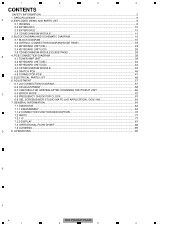
" A • Screw adjacent to mark on the product are not in this manual. (In the case of no amount instructions,apply as you think it appropriate.) 2.1 PACKING B 24 5 3 6 22 7 4 27 25 8 23 9 26 21 10 13 C 12 2 1 15 14 D 19 18 17 11 E 20 17 18 16 F 8 DEH-P9600MP/XN/EW 1 2 3 4 1 2 3 4 2. EXPLODED VIEWS AND PARTS LIST NOTES : • Parts marked by " * " are generally unavailable because they are used for disassembly. • For the applying amount of lobricants or glue, follow the instructions in our Master Spare Parts List.
" A • Screw adjacent to mark on the product are not in this manual. (In the case of no amount instructions,apply as you think it appropriate.) 2.1 PACKING B 24 5 3 6 22 7 4 27 25 8 23 9 26 21 10 13 C 12 2 1 15 14 D 19 18 17 11 E 20 17 18 16 F 8 DEH-P9600MP/XN/EW 1 2 3 4 1 2 3 4 2. EXPLODED VIEWS AND PARTS LIST NOTES : • Parts marked by " * " are generally unavailable because they are used for disassembly. • For the applying amount of lobricants or glue, follow the instructions in our Master Spare Parts List.
Service Manual
Page 13
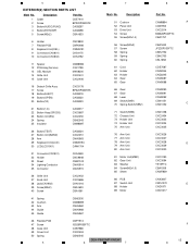
...Guide CBH2530 CNM8895 CNV6962 CNV6968 CNV6967 46 Flexible PCB 47 Screw 48 Case Unit 49 Cover Unit 50 Spring 5 CNP7913 ISS26P055FTC CXB7968 CXC2453 CBH2545 DEH-P9600MP/XN/EW 6 7 8 Part No. CNM8894 A CXB7953 CXC2514 BMZ26P040FTC CBA1757 CBA1633 JFZ20P030FTC CBH2752 CBH2753 CBL1658 B CDE7587 CND2244 CND2245 CNV8087 CNV8088 CNV8090 CNV8091 CNV8092 CSN1051 C CSN1052...Screw(M2x2) 40 Screw CXC2452 CXC3686 CKN1016 CBA1633 CBA1561 7 Mark No. Description 1 Cable 2 Screw 3 Button(AUDIO,FUNC) 4 Button(ENT,DISP) 5 Screw(M2x2) Part No. 5 6 EXTERIOR(2) SECTION PARTS LIST Mark No.
...Guide CBH2530 CNM8895 CNV6962 CNV6968 CNV6967 46 Flexible PCB 47 Screw 48 Case Unit 49 Cover Unit 50 Spring 5 CNP7913 ISS26P055FTC CXB7968 CXC2453 CBH2545 DEH-P9600MP/XN/EW 6 7 8 Part No. CNM8894 A CXB7953 CXC2514 BMZ26P040FTC CBA1757 CBA1633 JFZ20P030FTC CBH2752 CBH2753 CBL1658 B CDE7587 CND2244 CND2245 CNV8087 CNV8088 CNV8090 CNV8091 CNV8092 CSN1051 C CSN1052...Screw(M2x2) 40 Screw CXC2452 CXC3686 CKN1016 CBA1633 CBA1561 7 Mark No. Description 1 Cable 2 Screw 3 Button(AUDIO,FUNC) 4 Button(ENT,DISP) 5 Screw(M2x2) Part No. 5 6 EXTERIOR(2) SECTION PARTS LIST Mark No.

Service Manual
Page 15
Description Part No. 1 CD Core Unit(S10WMACODE2) CWX2953 2 Connector(CN101) CKS4182 3 Connector(CN901) CKS4017 4 Screw BMZ20P035FTC 5 Screw BSZ20P040FTC 6 Screw(M2x4) 7 ... CND1896 CND1894 CXB8933 CNC9985 EBA1028 JFZ20P020FTC JGZ17P022FTC E YE20FTC CXX1641 IMS26P030FTC CBL1635 CNV7197 CKS2193 F 15 8 5 6 CD MECHANISM MODULE SECTION PARTS LIST Mark No. Description 51 Gear 52 Gear 53 Gear 54 Gear 55 Gear 56 Rack 57 Arm 58 Arm 59 Guide 60...(CN902) 46 Rack 47 Holder 48 Holder 49 Arm 50 Gear 5 CNV7199 CNV7201 CNV7202 CNV7203 CNV7207 6 DEH-P9600MP/XN/EW 7 8 Part No.
Description Part No. 1 CD Core Unit(S10WMACODE2) CWX2953 2 Connector(CN101) CKS4182 3 Connector(CN901) CKS4017 4 Screw BMZ20P035FTC 5 Screw BSZ20P040FTC 6 Screw(M2x4) 7 ... CND1896 CND1894 CXB8933 CNC9985 EBA1028 JFZ20P020FTC JGZ17P022FTC E YE20FTC CXX1641 IMS26P030FTC CBL1635 CNV7197 CKS2193 F 15 8 5 6 CD MECHANISM MODULE SECTION PARTS LIST Mark No. Description 51 Gear 52 Gear 53 Gear 54 Gear 55 Gear 56 Rack 57 Arm 58 Arm 59 Guide 60...(CN902) 46 Rack 47 Holder 48 Holder 49 Arm 50 Gear 5 CNV7199 CNV7201 CNV7202 CNV7203 CNV7207 6 DEH-P9600MP/XN/EW 7 8 Part No.
Service Manual
Page 18
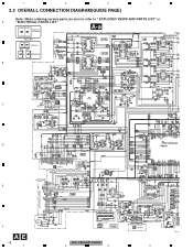
Large size A-a A-b SCH diagram A-a A-a A-b Guide page A-a A-b Detailed page B 1 2 3 C E M M951 AUTOMATIC FLAP SWITCH S952 CSN1052 (CLOSE) S951 CSN1051 (OPEN) S953 CSN1058 (EJECT) CXB8939 PCB CN902 FM/AM TUNER UNIT D D CN901 TUNER:-26.0dBs (FM:30%, AM:30%) E F AE 18 1 IP-BUS:+2.2dBs DEH-P9600MP/XN/EW 2 3 B CN1801 4 4 1 2 3 4 3.2 OVERALL CONNECTION DIAGRAM(GUIDE PAGE) Note: When ordering service parts, be sure to refer to " EXPLODED VIEWS AND PARTS LIST" or A "ELECTRICAL PARTS LIST".
Large size A-a A-b SCH diagram A-a A-a A-b Guide page A-a A-b Detailed page B 1 2 3 C E M M951 AUTOMATIC FLAP SWITCH S952 CSN1052 (CLOSE) S951 CSN1051 (OPEN) S953 CSN1058 (EJECT) CXB8939 PCB CN902 FM/AM TUNER UNIT D D CN901 TUNER:-26.0dBs (FM:30%, AM:30%) E F AE 18 1 IP-BUS:+2.2dBs DEH-P9600MP/XN/EW 2 3 B CN1801 4 4 1 2 3 4 3.2 OVERALL CONNECTION DIAGRAM(GUIDE PAGE) Note: When ordering service parts, be sure to refer to " EXPLODED VIEWS AND PARTS LIST" or A "ELECTRICAL PARTS LIST".

Service Manual
Page 19
No differentiation is shown with the marked box. ← ← DEH-P9600MP/XN/EW 6 7 F A 19 8 Symbol indicates a capacitor. Decimal points for resistor and capacitor fixed values are expressed as : 2.2 2R2 0.022 R022 : The power supply is made ...:+7.66dBs CD:+7.55dBs TUNER:-27.3dBs IP-BUS:+1.73dBs 7 8 A A-b The > mark found on some component parts indicates the importance of the safety factor of identical designation. Therefore, when replacing, be sure to use parts of the part. A TUNER AMP UNIT TUNER: +6.13dBs IP-BUS:+18.16dBs CD:+18.05dBs > SUB WOOFER R CH SUB...
No differentiation is shown with the marked box. ← ← DEH-P9600MP/XN/EW 6 7 F A 19 8 Symbol indicates a capacitor. Decimal points for resistor and capacitor fixed values are expressed as : 2.2 2R2 0.022 R022 : The power supply is made ...:+7.66dBs CD:+7.55dBs TUNER:-27.3dBs IP-BUS:+1.73dBs 7 8 A A-b The > mark found on some component parts indicates the importance of the safety factor of identical designation. Therefore, when replacing, be sure to use parts of the part. A TUNER AMP UNIT TUNER: +6.13dBs IP-BUS:+18.16dBs CD:+18.05dBs > SUB WOOFER R CH SUB...

Service Manual
Page 22
A TUNER AMP UNIT TUNER: +6.13dBs IP-BUS:+18.16dBs CD:+18.05dBs > SUB WOOFER R CH SUB WOOFER L CH REAR R CH REAR L CH FRONT R CH FRONT L CH B A 4 3 2 1 Therefore, when replacing, be sure to use parts of the part. 3 4 3 2 DEH-P9600MP/XN/EW 2 F A-b 1 22 1 E TUNER: -4.37dBs IP-BUS:+7.66dBs CD:+7.55dBs TUNER:-27.3dBs IP-BUS:+1.73dBs D C A-a A-b The > mark found on some component parts indicates the importance of the safety factor of identical designation.
A TUNER AMP UNIT TUNER: +6.13dBs IP-BUS:+18.16dBs CD:+18.05dBs > SUB WOOFER R CH SUB WOOFER L CH REAR R CH REAR L CH FRONT R CH FRONT L CH B A 4 3 2 1 Therefore, when replacing, be sure to use parts of the part. 3 4 3 2 DEH-P9600MP/XN/EW 2 F A-b 1 22 1 E TUNER: -4.37dBs IP-BUS:+7.66dBs CD:+7.55dBs TUNER:-27.3dBs IP-BUS:+1.73dBs D C A-a A-b The > mark found on some component parts indicates the importance of the safety factor of identical designation.

Service Manual
Page 38
For further information for several destination. PCB CONNECTION DIAGRAM 4.1 TUNER AMP UNIT A NOTE FOR PCB DIAGRAMS 1.The parts mounted on this PCB A TUNER AMP UNIT include all necessary parts for respective destinations, be sure to check with the schematic dia- gram. 2.Viewpoint of PCB diagrams Connector Capacitor SIDE A B P.C.Board Chip Part SIDE B 3 CORD ASSY 4 ANTENNA CABLE IP BUS TEL C WIRED REMOTE CONTROL D D CN902 E F A 38 1 DEH-P9600MP/XN/EW 2 3 B CN1801 FRONT 4 1 2 4.
For further information for several destination. PCB CONNECTION DIAGRAM 4.1 TUNER AMP UNIT A NOTE FOR PCB DIAGRAMS 1.The parts mounted on this PCB A TUNER AMP UNIT include all necessary parts for respective destinations, be sure to check with the schematic dia- gram. 2.Viewpoint of PCB diagrams Connector Capacitor SIDE A B P.C.Board Chip Part SIDE B 3 CORD ASSY 4 ANTENNA CABLE IP BUS TEL C WIRED REMOTE CONTROL D D CN902 E F A 38 1 DEH-P9600MP/XN/EW 2 3 B CN1801 FRONT 4 1 2 4.
Service Manual
Page 49
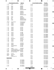
... R 105 RS1/16S562J RS1/16S332J RS1/16S181J RS1/16S181J RS1/16S223J R 233 R 234 R 235 R 236 R 237 R 106 R 107 RS1/16S223J RS1/16S102J R 238 R 239 DEH-P9600MP/XN/EW 5 6 7 Part No. Circuit Symbol and No. RS1/16S102J RS1/16S222J RS1/16S101J RS1/16S101J RS1/16S102J RS1/16S150J RS1/16S470J RAB4C0R0J RS1/16S0R0J RS1/16S0R0J... RS1/16S103J RS1/16S103J RS1/16S102J RS1/16S223J RS1/16S223J RS1/16S223J RS1/16S223J RS1/16S223J RS1/16S223J RS1/16S331J RS1/16S331J RS1/16S331J 8 A B C D E F 49 Part No.
... R 105 RS1/16S562J RS1/16S332J RS1/16S181J RS1/16S181J RS1/16S223J R 233 R 234 R 235 R 236 R 237 R 106 R 107 RS1/16S223J RS1/16S102J R 238 R 239 DEH-P9600MP/XN/EW 5 6 7 Part No. Circuit Symbol and No. RS1/16S102J RS1/16S222J RS1/16S101J RS1/16S101J RS1/16S102J RS1/16S150J RS1/16S470J RAB4C0R0J RS1/16S0R0J RS1/16S0R0J... RS1/16S103J RS1/16S103J RS1/16S102J RS1/16S223J RS1/16S223J RS1/16S223J RS1/16S223J RS1/16S223J RS1/16S223J RS1/16S331J RS1/16S331J RS1/16S331J 8 A B C D E F 49 Part No.
Service Manual
Page 65
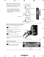
... place a product, please go in Fig.3 until the Arm Unit moves to the 3 positions of a Fig.3. *) There is a possibility of the grille parts. Removing the Detach Grille Assy and Grille Assy Move the Arm Unit to the OPEN POSITION. (Fig.3) 1 Remove the two screws. (Fig.4) Disconnect the ...arm parts, It becomes the cause of defect of move of bending if load is also installed. 2 Remove the two screws. (Fig.4) Move the Arm Unit to the OPEN POSITION. (Fig.3) 1 Remove the two screws and then remove the Panel Unit. (Fig.5) 1 1 Fig.3 C D Fig.4 E Panel Unit Fig.5 F DEH-P9600MP/XN...
... place a product, please go in Fig.3 until the Arm Unit moves to the 3 positions of a Fig.3. *) There is a possibility of the grille parts. Removing the Detach Grille Assy and Grille Assy Move the Arm Unit to the OPEN POSITION. (Fig.3) 1 Remove the two screws. (Fig.4) Disconnect the ...arm parts, It becomes the cause of defect of move of bending if load is also installed. 2 Remove the two screws. (Fig.4) Move the Arm Unit to the OPEN POSITION. (Fig.3) 1 Remove the two screws and then remove the Panel Unit. (Fig.5) 1 1 Fig.3 C D Fig.4 E Panel Unit Fig.5 F DEH-P9600MP/XN...
Service Manual
Page 73
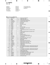
Pin Functions(PD5913A) Pin No. 5 7.2 PARTS 7.2.1 IC PD5913A BD4835G PCM1606EG AK7730VT HA12240FP TC7WH32FK 6 7 PD5917A PD6340A PD8122A PD6460A UPD63761GJ PE5423A S-812C33AUA-C2N S-L2980A15MC-C6A BA5835FM - Pin Name I/O 1 BSO O 2 bsck I/O 3 DUALILM O 4 CSENSOUT O 5 DSPOUT O 6 ... input Clock adjustment output OEL display microcomputer power output LCD power supply control output OEL illumination power output LCD illumination power output DSP power output DEH-P9600MP/XN/EW 5 6 7 8 A B C D E F 73 8
Pin Functions(PD5913A) Pin No. 5 7.2 PARTS 7.2.1 IC PD5913A BD4835G PCM1606EG AK7730VT HA12240FP TC7WH32FK 6 7 PD5917A PD6340A PD8122A PD6460A UPD63761GJ PE5423A S-812C33AUA-C2N S-L2980A15MC-C6A BA5835FM - Pin Name I/O 1 BSO O 2 bsck I/O 3 DUALILM O 4 CSENSOUT O 5 DSPOUT O 6 ... input Clock adjustment output OEL display microcomputer power output LCD power supply control output OEL illumination power output LCD illumination power output DSP power output DEH-P9600MP/XN/EW 5 6 7 8 A B C D E F 73 8


