Owner's Manual
Page 2
Contents Before Using This Product 2 Information to User 2 Inportant 2 After-sales service for Pioneer products .......... 2 CAUTION 3 Visit our website 3 CAUTION 3 WARNING 4 Setting the Unit 5 Power Indicator 5 Top Cover 5 Cut Off Frequency Control 5 BFC (Beat Frequency Control) Switch 5 LPF (Low-...
Contents Before Using This Product 2 Information to User 2 Inportant 2 After-sales service for Pioneer products .......... 2 CAUTION 3 Visit our website 3 CAUTION 3 WARNING 4 Setting the Unit 5 Power Indicator 5 Top Cover 5 Cut Off Frequency Control 5 BFC (Beat Frequency Control) Switch 5 LPF (Low-...
Owner's Manual
Page 3
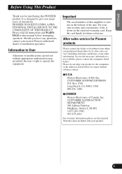
...199;AIS ITALIANO NEDERLANDS Before Using This Product Thank you have any other information. Please read all instructions and WARNINGS in this amplifier is written on the enclosed warranty card. Information to User Alteration or modifications carried out without advance contact. 7 U.S.A. In... case the necessary information is designed to operate the equipment. Should you for Pioneer products Please contact the dealer or distributor from where you many years of enjoyment. Important The serial number of this manual before...
...199;AIS ITALIANO NEDERLANDS Before Using This Product Thank you have any other information. Please read all instructions and WARNINGS in this amplifier is written on the enclosed warranty card. Information to User Alteration or modifications carried out without advance contact. 7 U.S.A. In... case the necessary information is designed to operate the equipment. Should you for Pioneer products Please contact the dealer or distributor from where you many years of enjoyment. Important The serial number of this manual before...
Owner's Manual
Page 4
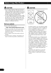
... in damage to achieve a 2 Ohm (or lower) bridged mode (Diagram B). Pioneer Amplifier 4 Ohm Bridged Mode 4 + Ohm Speaker L+ R- For a four-channel amplifier, follow the speaker output connection diagram for a two-channel amplifier and achieve a 4 Ω load, wire two 8 Ω speakers in ...parallel with one of your product. We will keep the details of your local authorized Pioneer dealer or call Pioneer customer service. 3 Improper 4 + Ohm Speaker 8 + Ohm Speaker L+ R- Amplifier damage, smoke, and overheating could result in parallel to achieve a 4 Ω load ...
... in damage to achieve a 2 Ohm (or lower) bridged mode (Diagram B). Pioneer Amplifier 4 Ohm Bridged Mode 4 + Ohm Speaker L+ R- For a four-channel amplifier, follow the speaker output connection diagram for a two-channel amplifier and achieve a 4 Ω load, wire two 8 Ω speakers in ...parallel with one of your product. We will keep the details of your local authorized Pioneer dealer or call Pioneer customer service. 3 Improper 4 + Ohm Speaker 8 + Ohm Speaker L+ R- Amplifier damage, smoke, and overheating could result in parallel to achieve a 4 Ω load ...

Owner's Manual
Page 5
...normal traffic sound. • Check the connections of the power supply and speakers if the fuse of the separately sold battery wire or the amplifier fuse blows. Detect the cause and solve the problem. • Contact the dealer if you may get an electric shock. Electrical shock ...cause cancer and birth defects or other governmental entities to the system OFF and check the connection of the power supply and speakers. Also, amplifier and speaker damage, smoke, and overheating could result. ENGLISH ESPAÑOL DEUTSCH FRANÇAIS ITALIANO NEDERLANDS WARNING • Handling the ...
...normal traffic sound. • Check the connections of the power supply and speakers if the fuse of the separately sold battery wire or the amplifier fuse blows. Detect the cause and solve the problem. • Contact the dealer if you may get an electric shock. Electrical shock ...cause cancer and birth defects or other governmental entities to the system OFF and check the connection of the power supply and speakers. Also, amplifier and speaker damage, smoke, and overheating could result. ENGLISH ESPAÑOL DEUTSCH FRANÇAIS ITALIANO NEDERLANDS WARNING • Handling the ...
Owner's Manual
Page 6
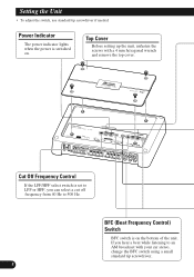
Top Cover Before setting up the unit, unfasten the screws with your car stereo, change the BFC switch using a small standard tip screwdriver. 5 Cut Off Frequency Control If the LPF/HPF select switch is set to LPF or HPF, you hear a beat while listening to 500 Hz. If you can select a cut off frequency from 40 Hz to an AM broadcast with a 4 mm hexagonal wrench and remove the top cover. Setting the Unit • To adjust the switch, use standard tip screwdriver if needed. BFC (Beat Frequency Control) Switch BFC switch is switched on the bottom of the unit. Power Indicator The power ...
Top Cover Before setting up the unit, unfasten the screws with your car stereo, change the BFC switch using a small standard tip screwdriver. 5 Cut Off Frequency Control If the LPF/HPF select switch is set to LPF or HPF, you hear a beat while listening to 500 Hz. If you can select a cut off frequency from 40 Hz to an AM broadcast with a 4 mm hexagonal wrench and remove the top cover. Setting the Unit • To adjust the switch, use standard tip screwdriver if needed. BFC (Beat Frequency Control) Switch BFC switch is switched on the bottom of the unit. Power Indicator The power ...
Owner's Manual
Page 7
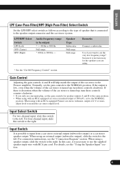
... and B will help match the output of 4 V or more, adjust level to match the car stereo output level. When using with an RCA equipped Pioneer car stereo with RCA pin cord. For connection instructions, see the "Using the Speaker Input" section. 6 Normally, set the gain controls to the right.... is possible to input from a car stereo external output (subwoofer output) or a car stereo speaker output. output of the car stereo to the Pioneer amplifier. For four-channel input, slide this case, it is necessary to use one input plug, set to cut the very low frequency range* because ...
... and B will help match the output of 4 V or more, adjust level to match the car stereo output level. When using with an RCA equipped Pioneer car stereo with RCA pin cord. For connection instructions, see the "Using the Speaker Input" section. 6 Normally, set the gain controls to the right.... is possible to input from a car stereo external output (subwoofer output) or a car stereo speaker output. output of the car stereo to the Pioneer amplifier. For four-channel input, slide this case, it is necessary to use one input plug, set to cut the very low frequency range* because ...
Owner's Manual
Page 8
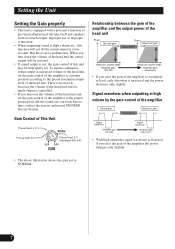
...gain control of the amplifier Normal gain Equal power Maximum gain Signal waveform Amplifier gain (normal) Signal waveform Amplifier gain (maximum) ... head unit, set the gain control of the amplifier to the proper position but still the sound cuts out...output is controlled. • If you raise the gain of the amplifier to an improper level, only distortion is increased and the power increases...mV) Relationship between the gain of the amplifier and the output power of the head unit Power Normal gain Power Maximum...and set the gain control of the amplifier to a proper position according to the...
...gain control of the amplifier Normal gain Equal power Maximum gain Signal waveform Amplifier gain (normal) Signal waveform Amplifier gain (maximum) ... head unit, set the gain control of the amplifier to the proper position but still the sound cuts out...output is controlled. • If you raise the gain of the amplifier to an improper level, only distortion is increased and the power increases...mV) Relationship between the gain of the amplifier and the output power of the head unit Power Normal gain Power Maximum...and set the gain control of the amplifier to a proper position according to the...
Owner's Manual
Page 9
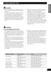
... than the original fuse. The speaker impedance must be 2 to 8 ohms. But in a short-circuit through the ignition switch (12 V DC), the amplifier will not interfere with cable clamps or adhesive tape. input: Min. 600 W Nominal input: Min. 70 W Max. Otherwise the protection circuit may fail ... a 12-volt battery and negative grounding. regardless of whether the car stereo is at rest or idling. • Speakers to be connected to the amplifier should . • Never feed power to other bridge connections, the speaker impedance must be 4 to 8 ohms. • Install and route the ...
... than the original fuse. The speaker impedance must be 2 to 8 ohms. But in a short-circuit through the ignition switch (12 V DC), the amplifier will not interfere with cable clamps or adhesive tape. input: Min. 600 W Nominal input: Min. 70 W Max. Otherwise the protection circuit may fail ... a 12-volt battery and negative grounding. regardless of whether the car stereo is at rest or idling. • Speakers to be connected to the amplifier should . • Never feed power to other bridge connections, the speaker impedance must be 4 to 8 ohms. • Install and route the ...
Owner's Manual
Page 10
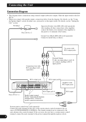
...If only one input plug is used, do not connect anything to metal body or chassis. RCA output jack RCA input jack B Amplifier with RCA pin plugs (sold separately) Connect the male terminal of this wire to the system remote control terminal of the battery. RCA...car stereo (SYSTEM REMOTE CONTROL). Ground wire (Black) [RD-228] (sold separately) After making all other connections at the amplifier, connect the battery wire terminal of the amplifier to set the input switch. Connecting the Unit Connection Diagram • This diagram shows connections using external output (subwoofer output)....
...If only one input plug is used, do not connect anything to metal body or chassis. RCA output jack RCA input jack B Amplifier with RCA pin plugs (sold separately) Connect the male terminal of this wire to the system remote control terminal of the battery. RCA...car stereo (SYSTEM REMOTE CONTROL). Ground wire (Black) [RD-228] (sold separately) After making all other connections at the amplifier, connect the battery wire terminal of the amplifier to set the input switch. Connecting the Unit Connection Diagram • This diagram shows connections using external output (subwoofer output)....
Owner's Manual
Page 11
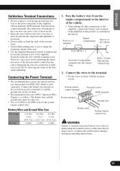
... necessary. • Do not solder or bind the ends of the twisted wires. • Fasten while making all other connections to the amplifier, connect the battery wire terminal of the wire. • Use the supplied hexagonal wrench to 20 AWG wire for the system remote control ... battery wire directly to the car battery positive terminal (+) and the ground wire to tighten excessively by observing the status of the amplifier. System remote control terminal Power terminal Terminal screws GND terminal Ground wire Battery wire System remote control wire WARNING Failure to securely fasten...
... necessary. • Do not solder or bind the ends of the twisted wires. • Fasten while making all other connections to the amplifier, connect the battery wire terminal of the wire. • Use the supplied hexagonal wrench to 20 AWG wire for the system remote control ... battery wire directly to the car battery positive terminal (+) and the ground wire to tighten excessively by observing the status of the amplifier. System remote control terminal Power terminal Terminal screws GND terminal Ground wire Battery wire System remote control wire WARNING Failure to securely fasten...
Owner's Manual
Page 12
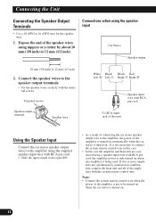
... (3/8 inch) to the speaker output terminals. • Fix the speaker wires securely with the system remote control wire. If two or more amplifiers are connected using the supplied speaker input wire with RCA pin cord To RCA input jack of this unit. Connect the speaker wires to 12... head unit are synchronously connected in combination, connect the head unit and all of the amplifier is turned on automatically when the car stereo is not necessary to the amplifier, the power of the amplifiers with the terminal screws. It is turned on. Note: • Connect the system remote control...
... (3/8 inch) to the speaker output terminals. • Fix the speaker wires securely with the system remote control wire. If two or more amplifiers are connected using the supplied speaker input wire with RCA pin cord To RCA input jack of this unit. Connect the speaker wires to 12... head unit are synchronously connected in combination, connect the head unit and all of the amplifier is turned on automatically when the car stereo is not necessary to the amplifier, the power of the amplifiers with the terminal screws. It is turned on. Note: • Connect the system remote control...

Owner's Manual
Page 13
For fourchannel input, slide this switch to the left . Three-channel Input select switch is used , such as when the car stereo has only one output (RCA output), connect the plug to RCA input jack A, but do not connect a plug to the figures shown below. RCA input jack A RCA input jack B (Right) Speaker out A (Left) Speaker out B (Mono) Connecting wires with RCA plugs (sold separately) From car stereo (RCA output) If only one input plug is on the top of the unit. Connect the speaker leads to suit the mode according to RCA input jack B. For twochannel input, slide this switch to ...
For fourchannel input, slide this switch to the left . Three-channel Input select switch is used , such as when the car stereo has only one output (RCA output), connect the plug to RCA input jack A, but do not connect a plug to the figures shown below. RCA input jack A RCA input jack B (Right) Speaker out A (Left) Speaker out B (Mono) Connecting wires with RCA plugs (sold separately) From car stereo (RCA output) If only one input plug is on the top of the unit. Connect the speaker leads to suit the mode according to RCA input jack B. For twochannel input, slide this switch to ...
Owner's Manual
Page 14
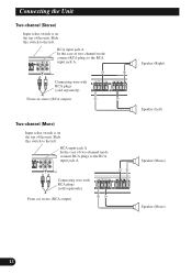
RCA input jack A In the case of two-channel mode connect RCA plugs to the RCA input jack A. Connecting the Unit Two-channel (Stereo) Input select switch is on the top of the unit. Connecting wire with RCA plugs (sold separately) From car stereo (RCA output) Speaker (Right) Speaker (Left) Speaker (Mono) Speaker (Mono) 13 Slide this switch to the left . RCA input jack A In the case of the unit. Slide this switch to the left . Connecting wire with RCA plugs (sold separately) From car stereo (RCA output) Two-channel (Mono) Input select switch is on the top of two-channel...
RCA input jack A In the case of two-channel mode connect RCA plugs to the RCA input jack A. Connecting the Unit Two-channel (Stereo) Input select switch is on the top of the unit. Connecting wire with RCA plugs (sold separately) From car stereo (RCA output) Speaker (Right) Speaker (Left) Speaker (Mono) Speaker (Mono) 13 Slide this switch to the left . RCA input jack A In the case of the unit. Slide this switch to the left . Connecting wire with RCA plugs (sold separately) From car stereo (RCA output) Two-channel (Mono) Input select switch is on the top of two-channel...
Owner's Manual
Page 15
... wires from damage. • Install tapping screws in such a way that the spare tire, jack and tools can result in fire. • DO NOT allow amplifier to come into contact with the car model and installation location. Use of an improper fuse could result in overheating and smoke and could cause... damage to the touch and minor burns could result. • Do not install the amplifier on the floor in front of the driver's seat. • Make sure that wires are not caught in the sliding mechanism of the seats, resulting...
... wires from damage. • Install tapping screws in such a way that the spare tire, jack and tools can result in fire. • DO NOT allow amplifier to come into contact with the car model and installation location. Use of an improper fuse could result in overheating and smoke and could cause... damage to the touch and minor burns could result. • Do not install the amplifier on the floor in front of the driver's seat. • Make sure that wires are not caught in the sliding mechanism of the seats, resulting...

Owner's Manual
Page 16
Replacing the top cover 1. Drill 2.5 mm (1/8 inch) diameter holes at the point marked, and install the amplifier, either on the carpet or directly to the amplifier. 2. Insert the supplied tapping screws (4 mm × 30 mm) into the screw holes. Tapping-screws (4 mm × 30 mm) Screw Top Cover Drill a 2.5 mm diameter ... can be located. 2. Installation Example of installation on the floor mat or on the screws with a 4 mm hexagonal wrench. Push on the chassis 1. Place the amplifier where it is to be installed in the desired direction to match to the chassis.
Replacing the top cover 1. Drill 2.5 mm (1/8 inch) diameter holes at the point marked, and install the amplifier, either on the carpet or directly to the amplifier. 2. Insert the supplied tapping screws (4 mm × 30 mm) into the screw holes. Tapping-screws (4 mm × 30 mm) Screw Top Cover Drill a 2.5 mm diameter ... can be located. 2. Installation Example of installation on the floor mat or on the screws with a 4 mm hexagonal wrench. Push on the chassis 1. Place the amplifier where it is to be installed in the desired direction to match to the chassis.
Owner's Manual
Page 17
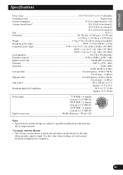
Use this value when working out total current drawn by this unit when an audio signal is nearly the maximum current drawn by multiple power amplifiers. 16 ENGLISH ESPAÑOL DEUTSCH FRANÇAIS ITALIANO NEDERLANDS Specifications Power source ...14.4 V DC (10.8 V to 15.1 V allowable) Grounding system ...Negative type Current ...
Use this value when working out total current drawn by this unit when an audio signal is nearly the maximum current drawn by multiple power amplifiers. 16 ENGLISH ESPAÑOL DEUTSCH FRANÇAIS ITALIANO NEDERLANDS Specifications Power source ...14.4 V DC (10.8 V to 15.1 V allowable) Grounding system ...Negative type Current ...