
Service Manual
Page 5
... (Q353, 354, 355, 356, 357, 358, 359, 360) 46 Screw SMZ50H300FCR (2) CONTRAST TABLE PRS-X340/X1R/UC and PRS-X340/X1R/EW are constructed the same except for the following: Part No. Description PRS-X340/X1R/UC PRS-X340/X1R/EW * 4 Badge HAM0013 HAM0014 14 Amp Unit HWH0132 HWH0124 31 Network Unit HWG0018 HWG0017 5 Description 26 Clip 27 Holder...
... (Q353, 354, 355, 356, 357, 358, 359, 360) 46 Screw SMZ50H300FCR (2) CONTRAST TABLE PRS-X340/X1R/UC and PRS-X340/X1R/EW are constructed the same except for the following: Part No. Description PRS-X340/X1R/UC PRS-X340/X1R/EW * 4 Badge HAM0013 HAM0014 14 Amp Unit HWH0132 HWH0124 31 Network Unit HWG0018 HWG0017 5 Description 26 Clip 27 Holder...
Service Manual
Page 6
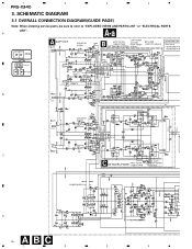
A A-a Large size A-a A-b SCH diagram A AMP UNIT CN851 ISOLATOR GAIN=1 LOW XOVER B HP/LP FILTER 12dB/OCTAVE 40-120Hz HIGH XOVER NETWORK PCB(A) 3k-9kHz BP FILTER LOW-X TO HIGH-X NETWORK ... DIAGRAM 3.1 OVERALL CONNECTION DIAGRAM(GUIDE PAGE) Note: When ordering service parts, be sure to refer to "EXPLODED VIEWS AND PARTS LIST" or "ELECTRICAL PARTS LIST". 1 2 3 4 PRS-X340 3.
A A-a Large size A-a A-b SCH diagram A AMP UNIT CN851 ISOLATOR GAIN=1 LOW XOVER B HP/LP FILTER 12dB/OCTAVE 40-120Hz HIGH XOVER NETWORK PCB(A) 3k-9kHz BP FILTER LOW-X TO HIGH-X NETWORK ... DIAGRAM 3.1 OVERALL CONNECTION DIAGRAM(GUIDE PAGE) Note: When ordering service parts, be sure to refer to "EXPLODED VIEWS AND PARTS LIST" or "ELECTRICAL PARTS LIST". 1 2 3 4 PRS-X340 3.
Service Manual
Page 7
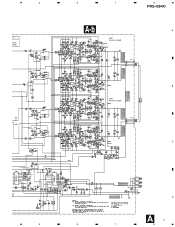
5 IT CB(A) CB(B) PRS-X340/X1R/EW 5 6 7 8 PRS-X340 A-b A AMP GAIN=8.5-33dB CN301 B AMP GAIN=8.5-33dB CN301 C CN904 CN903 CN902 CN901 D A7 6 7 8
5 IT CB(A) CB(B) PRS-X340/X1R/EW 5 6 7 8 PRS-X340 A-b A AMP GAIN=8.5-33dB CN301 B AMP GAIN=8.5-33dB CN301 C CN904 CN903 CN902 CN901 D A7 6 7 8
Service Manual
Page 8
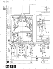
A B C D PRS-X340 1 8 A-a B C 1 2 2 A AMP UNIT CN851 ISOLATOR GAIN=1 CN851 RCA OUT GAIN=1 CN851 CN851 CN101 CN102 A-a A-b LOW XOVER B HP/LP FILTER 12dB/OCTAVE 40-120Hz BP FILTER HIGH XOVER LOW-X TO HIGH-X NETWORK PCB(A) 3k-9kHz NETWORK UNIT Consists of • NETWORK PCB(A) • NETWORK PCB(B) CN102-2 CN101-2 1 3 3 4 4 CN852 ISOLATOR GAIN=1 CN104-2 CN103-2 CN103 CN104
A B C D PRS-X340 1 8 A-a B C 1 2 2 A AMP UNIT CN851 ISOLATOR GAIN=1 CN851 RCA OUT GAIN=1 CN851 CN851 CN101 CN102 A-a A-b LOW XOVER B HP/LP FILTER 12dB/OCTAVE 40-120Hz BP FILTER HIGH XOVER LOW-X TO HIGH-X NETWORK PCB(A) 3k-9kHz NETWORK UNIT Consists of • NETWORK PCB(A) • NETWORK PCB(B) CN102-2 CN101-2 1 3 3 4 4 CN852 ISOLATOR GAIN=1 CN104-2 CN103-2 CN103 CN104

Service Manual
Page 12
For further information for several destination. Viewpoint of PCB diagrams Connector Capacitor SIDE A 4CH † 2CH P.C.Board B Chip Part SIDE B A AMP UNIT 3 4 C CN104 C D A 12 1 2 B CN102 3 4 PCB CONNECTION DIAGRAM 4.1 AMP UNIT NOTE FOR PCB DIAGRAMS A 1. The parts mounted on this PCB include all necessary parts for respective destinations, be sure to check with the schematic diagram. 2. 1 2 PRS-X340 4.
For further information for several destination. Viewpoint of PCB diagrams Connector Capacitor SIDE A 4CH † 2CH P.C.Board B Chip Part SIDE B A AMP UNIT 3 4 C CN104 C D A 12 1 2 B CN102 3 4 PCB CONNECTION DIAGRAM 4.1 AMP UNIT NOTE FOR PCB DIAGRAMS A 1. The parts mounted on this PCB include all necessary parts for respective destinations, be sure to check with the schematic diagram. 2. 1 2 PRS-X340 4.

Service Manual
Page 25
Remove the four screws and then remove the Case(Speaker). Case(RCA) Fig.1 Amp Unit Fig.2 25 Remove the two screws Remove the four screws and then remove the Case(RCA). Removing the Amp Unit (Fig.2) Remove the two screws. Removing the Case(Speaker) and the Case(RCA) (Fig.1) Case(Speaker) Remove the six screws. PRS-X340 - Remove the three screws. Remove the eight screws and then remove the Amp Unit. 7. GENERAL INFORMATION 7.1 DISASSEMBLY -
Remove the four screws and then remove the Case(Speaker). Case(RCA) Fig.1 Amp Unit Fig.2 25 Remove the two screws Remove the four screws and then remove the Case(RCA). Removing the Amp Unit (Fig.2) Remove the two screws. Removing the Case(Speaker) and the Case(RCA) (Fig.1) Case(Speaker) Remove the six screws. PRS-X340 - Remove the three screws. Remove the eight screws and then remove the Amp Unit. 7. GENERAL INFORMATION 7.1 DISASSEMBLY -

Service Manual
Page 31
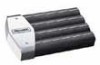
... Alexandra Road, #04-01, Singapore 159936 C PIONEER CORPORATION 2000 K-ZZS. CRT2646 BRIDGEABLE FOUR-CHANNEL POWER AMPLIFIER PRS-X340 X1H/UC PRS-X340 X1H/EW - Symbol and Description PRS-X340/X1R/EW PRS-X340/X1H/EW 14 Amp Unit HWH0124 HWH0156 31 Network Unit HWG0017 HWG0026 PIONEER CORPORATION 4-1, Meguro 1-Chome, Meguro-ku, Tokyo 153-8654, Japan PIONEER ELECTRONICS SERVICE INC. PACKING SECTION PARTS...
... Alexandra Road, #04-01, Singapore 159936 C PIONEER CORPORATION 2000 K-ZZS. CRT2646 BRIDGEABLE FOUR-CHANNEL POWER AMPLIFIER PRS-X340 X1H/UC PRS-X340 X1H/EW - Symbol and Description PRS-X340/X1R/EW PRS-X340/X1H/EW 14 Amp Unit HWH0124 HWH0156 31 Network Unit HWG0017 HWG0026 PIONEER CORPORATION 4-1, Meguro 1-Chome, Meguro-ku, Tokyo 153-8654, Japan PIONEER ELECTRONICS SERVICE INC. PACKING SECTION PARTS...


