

Owners Manual
Page 3
...• To prevent malfunction of the amplifier and speakers, the protective circuit will cut the power supply to the system OFF and check the connection of trouble When the unit does not operate properly, contact your dealer or the nearest authorized PIONEER Service Station. Detect the cause and ... the fuse with wet hands. Be sure to read this PIONEER product. Before attempting operation, be sure to maintain safe driving conditions, keep the volume low enough so that no parts are sold battery wire or the amplifier fuse blows. ENGLISH ESPAÑOL DEUTSCH Before Using This ...
...• To prevent malfunction of the amplifier and speakers, the protective circuit will cut the power supply to the system OFF and check the connection of trouble When the unit does not operate properly, contact your dealer or the nearest authorized PIONEER Service Station. Detect the cause and ... the fuse with wet hands. Be sure to read this PIONEER product. Before attempting operation, be sure to maintain safe driving conditions, keep the volume low enough so that no parts are sold battery wire or the amplifier fuse blows. ENGLISH ESPAÑOL DEUTSCH Before Using This ...
Owners Manual
Page 4
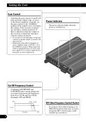
...for speaker outputs A and B to the same position. • When using with your car stereo, change the BFC switch using with an RCA equipped Pioneer car stereo with max. Setting the Unit Gain Control Adjusting the gain controls A and B will help match the output of 4 V or more, adjust...(Example: LPF and HIGH) (dB) 0 -3 Level (3 kHz) (9 kHz) Frequency (Hz) 3 BFC (Beat Frequency Control) Switch If you hear a beat while listening to the Pioneer amplifier. output of the car stereo to an MW/LW broadcast with an RCA equipped car stereo (standard output of the car stereo is turned up...
...for speaker outputs A and B to the same position. • When using with your car stereo, change the BFC switch using with an RCA equipped Pioneer car stereo with max. Setting the Unit Gain Control Adjusting the gain controls A and B will help match the output of 4 V or more, adjust...(Example: LPF and HIGH) (dB) 0 -3 Level (3 kHz) (9 kHz) Frequency (Hz) 3 BFC (Beat Frequency Control) Switch If you hear a beat while listening to the Pioneer amplifier. output of the car stereo to an MW/LW broadcast with an RCA equipped car stereo (standard output of the car stereo is turned up...
Owners Manual
Page 6
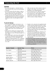
...vehicle, such as possible from the speaker wires. input: Min. 95 W Nominal input: Min. 330 W Max. Before installing it may be 2 to the amplifier should conform with the standards listed below. input: Min. 330 W Nominal input: Min. 95 W Max. If the insulation heats up, it in a recreational ... ohms. • Install and route the separately sold battery wire, ground wire, speaker wires and the amplifier as far away as possible from the wire. The current capacity of the amplifier is connected to the power terminal through the vehicle body. • Make sure that have the same ...
...vehicle, such as possible from the speaker wires. input: Min. 95 W Nominal input: Min. 330 W Max. Before installing it may be 2 to the amplifier should conform with the standards listed below. input: Min. 330 W Nominal input: Min. 95 W Max. If the insulation heats up, it in a recreational ... ohms. • Install and route the separately sold battery wire, ground wire, speaker wires and the amplifier as far away as possible from the wire. The current capacity of the amplifier is connected to the power terminal through the vehicle body. • Make sure that have the same ...
Owners Manual
Page 7
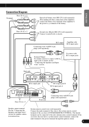
...not have a system remote control terminal, connect the male terminal to RCA input jacks A and B, see the "Connecting the Speakers and Input wires" section. Amplifier with RCA input jacks External Output For details on how to connect to the power terminal through the ignition switch. 6 Fuse (30 A) × 2 ...Ground wire (Black) [RD-223] (sold separately). System remote control wire (sold separately). After making all other connections at the amplifier, connect the battery wire terminal of the amplifier to the system remote control terminal of the battery.
...not have a system remote control terminal, connect the male terminal to RCA input jacks A and B, see the "Connecting the Speakers and Input wires" section. Amplifier with RCA input jacks External Output For details on how to connect to the power terminal through the ignition switch. 6 Fuse (30 A) × 2 ...Ground wire (Black) [RD-223] (sold separately). System remote control wire (sold separately). After making all other connections at the amplifier, connect the battery wire terminal of the amplifier to the system remote control terminal of the battery.
Owners Manual
Page 8
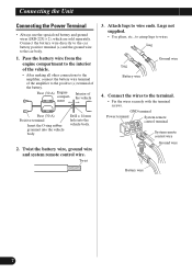
Pass the battery wire from the engine compartment to the interior of the vehicle. • After making all other connections to the amplifier, connect the battery wire terminal of the amplifier to the terminal. • Fix the wires securely with the terminal screws. Twist 3. Drill a 14 mm hole into the vehicle body. the...
Pass the battery wire from the engine compartment to the interior of the vehicle. • After making all other connections to the amplifier, connect the battery wire terminal of the amplifier to the terminal. • Fix the wires securely with the terminal screws. Twist 3. Drill a 14 mm hole into the vehicle body. the...
Owners Manual
Page 12
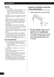
... holes. Protect all cables and important equipment such as fuel lines, brake lines and electrical wiring from being cut by vibration of the amplifier, or they make marks where the installation holes are behind the panel when drilling a hole for installation of installation on the floor mat...where it could injure the driver or passengers if the vehicle stops suddenly. -Places where it may get wet. • Do not install the amplifier on unstable places such as the spare tire board. • The best location for installation differs with the car model and installation location. Place...
... holes. Protect all cables and important equipment such as fuel lines, brake lines and electrical wiring from being cut by vibration of the amplifier, or they make marks where the installation holes are behind the panel when drilling a hole for installation of installation on the floor mat...where it could injure the driver or passengers if the vehicle stops suddenly. -Places where it may get wet. • Do not install the amplifier on unstable places such as the spare tire board. • The best location for installation differs with the car model and installation location. Place...
Owners Manual
Page 13
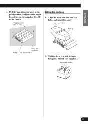
Screw Endcap Floor mat or chassis Drill a 2.5 mm diameter hole 2. Drill 2.5 mm diameter holes at the point marked, and install the amplifier, either on the carpet or directly to the chassis. Align the main unit and end cap holes, and insert the screw. Hexagonal wrench DEUTSCH FRANÇAIS ITALIANO NEDERLANDS 12 ENGLISH ESPAÑOL 3. Tighten the screw with a 4 mm hexagonal wrench (not supplied). Tapping-screws (4 × 18 mm) Fitting the end cap 1.
Screw Endcap Floor mat or chassis Drill a 2.5 mm diameter hole 2. Drill 2.5 mm diameter holes at the point marked, and install the amplifier, either on the carpet or directly to the chassis. Align the main unit and end cap holes, and insert the screw. Hexagonal wrench DEUTSCH FRANÇAIS ITALIANO NEDERLANDS 12 ENGLISH ESPAÑOL 3. Tighten the screw with a 4 mm hexagonal wrench (not supplied). Tapping-screws (4 × 18 mm) Fitting the end cap 1.
Owners Manual
Page 15
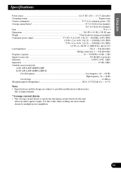
Use this value when working out total current drawn by this unit when an audio signal is nearly the maximum current drawn by multiple power amplifiers. 14 FRANÇAIS ITALIANO NEDERLANDS ENGLISH ESPAÑOL DEUTSCH Specifications Power source ...14.4 V DC (10.8 - 15.1 V allowable) Grounding system ...Negative type Current consumption ......
Use this value when working out total current drawn by this unit when an audio signal is nearly the maximum current drawn by multiple power amplifiers. 14 FRANÇAIS ITALIANO NEDERLANDS ENGLISH ESPAÑOL DEUTSCH Specifications Power source ...14.4 V DC (10.8 - 15.1 V allowable) Grounding system ...Negative type Current consumption ......

Service Manual
Page 1
... 7.1 DISASSEMBLY 25 8. ELECTRICAL PARTS LIST 18 6. P.O.Box 1760, Long Beach, CA 90801-1760 U.S.A. Service PRS-X340/X1R/UC Manual BRIDGEABLE FOUR-CHANNEL POWER AMPLIFIER PRS-X340 ORDER NO. OPERATIONS AND SPECIFICATIONS 26 PIONEER CORPORATION 4-1, Meguro 1-Chome, Meguro-ku, Tokyo 153-8654, Japan PIONEER ELECTRONICS SERVICE INC. MAR. 2000 Printed in Japan ADJUSTMENT 24 7. SCHEMATIC DIAGRAM 6 4. PCB CONNECTION...
... 7.1 DISASSEMBLY 25 8. ELECTRICAL PARTS LIST 18 6. P.O.Box 1760, Long Beach, CA 90801-1760 U.S.A. Service PRS-X340/X1R/UC Manual BRIDGEABLE FOUR-CHANNEL POWER AMPLIFIER PRS-X340 ORDER NO. OPERATIONS AND SPECIFICATIONS 26 PIONEER CORPORATION 4-1, Meguro 1-Chome, Meguro-ku, Tokyo 153-8654, Japan PIONEER ELECTRONICS SERVICE INC. MAR. 2000 Printed in Japan ADJUSTMENT 24 7. SCHEMATIC DIAGRAM 6 4. PCB CONNECTION...

Service Manual
Page 24
... Idle Current The following ranges will require you to measure the voltage across Resistor R434 and set VR502 to set when the amplifier has not been run for setting Idle current: Setting the idle current to the following is performed with no loads on the outputs with no signal input. ADJUSTMENT - PRS-X340 6.
... Idle Current The following ranges will require you to measure the voltage across Resistor R434 and set VR502 to set when the amplifier has not been run for setting Idle current: Setting the idle current to the following is performed with no loads on the outputs with no signal input. ADJUSTMENT - PRS-X340 6.
Service Manual
Page 27
PRS-X340 27 Gain Control Adjusting the gain controls A and B will help match the output of 500 mV), set to the NORMAL position. Cut Off Frequency Control ... switch settings lets you must set the CH B to HPF-HIGH. *4 Be sure to set the LOW/HIGH select switch to the Pioneer amplifier. When using with an RCA equipped Pioneer car stereo with an RCA equipped car stereo (standard output of the car stereo to HIGH. For four-channel input, slide this...
PRS-X340 27 Gain Control Adjusting the gain controls A and B will help match the output of 500 mV), set to the NORMAL position. Cut Off Frequency Control ... switch settings lets you must set the CH B to HPF-HIGH. *4 Be sure to set the LOW/HIGH select switch to the Pioneer amplifier. When using with an RCA equipped Pioneer car stereo with an RCA equipped car stereo (standard output of the car stereo to HIGH. For four-channel input, slide this...

Service Manual
Page 28
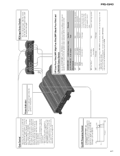
Connecting wires with RCA pin plugs (sold separately). After making all other connections at the amplifier, connect the battery wire terminal of the amplifier to RCA input jacks A and B, see the "Connecting the Speakers and Input wires" section. Car stereo with RCA output jacks... wire (black) [RD-223] (sold separately) Connect the male terminal of this wire to metal body or chassis. RCA input Amplifier with RCA pin plugs (sold separately). PRS-X340 Connection Diagram Fuse (30 A) × 2 Grommet Fuse (30 A) × 2 Special red battery wire [RD-223] (sold separately).
Connecting wires with RCA pin plugs (sold separately). After making all other connections at the amplifier, connect the battery wire terminal of the amplifier to RCA input jacks A and B, see the "Connecting the Speakers and Input wires" section. Car stereo with RCA output jacks... wire (black) [RD-223] (sold separately) Connect the male terminal of this wire to metal body or chassis. RCA input Amplifier with RCA pin plugs (sold separately). PRS-X340 Connection Diagram Fuse (30 A) × 2 Grommet Fuse (30 A) × 2 Special red battery wire [RD-223] (sold separately).
Service Manual
Page 29
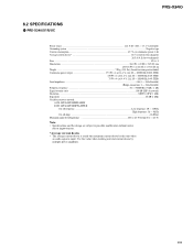
PRS-X340 8.2 SPECIFICATIONS - PRS-X340/X1R/UC Power source ...14.4 V DC (10.8 - 15.1 V allowable) Grounding system ...Negative type Current consumption ...43.7 A (at continuous power, 4 Ω) Average current drawn* ...14.5 A (4 Ω ... to possible modification without notice due to improvements. *Average current drawn • The average current drawn is nearly the maximum current drawn by multiple power amplifiers. 29 Use this value when working out total current drawn by this unit when an audio signal is input.
PRS-X340 8.2 SPECIFICATIONS - PRS-X340/X1R/UC Power source ...14.4 V DC (10.8 - 15.1 V allowable) Grounding system ...Negative type Current consumption ...43.7 A (at continuous power, 4 Ω) Average current drawn* ...14.5 A (4 Ω ... to possible modification without notice due to improvements. *Average current drawn • The average current drawn is nearly the maximum current drawn by multiple power amplifiers. 29 Use this value when working out total current drawn by this unit when an audio signal is input.

Service Manual
Page 30
PRS-X340 - PRS-X340/X1R/EW Power source ...14.4 V DC (10.8 - 15.1 V allowable) Grounding system ...Negative type Current consumption ...43.7 A (at continuous power, 4 Ω) Average current drawn* ...14.5 A (4 Ω ... to possible modification without notice due to improvements. *Average current drawn • The average current drawn is nearly the maximum current drawn by multiple power amplifiers. Use this value when working out total current drawn by this unit when an audio signal is input.
PRS-X340 - PRS-X340/X1R/EW Power source ...14.4 V DC (10.8 - 15.1 V allowable) Grounding system ...Negative type Current consumption ...43.7 A (at continuous power, 4 Ω) Average current drawn* ...14.5 A (4 Ω ... to possible modification without notice due to improvements. *Average current drawn • The average current drawn is nearly the maximum current drawn by multiple power amplifiers. Use this value when working out total current drawn by this unit when an audio signal is input.

Service Manual
Page 31
...PIONEER ELECTRONICS SERVICE INC. Mark No. Mech. Symbol and Description PRS-X340/X1R/UC PRS-X340/X1H/UC 14 Amp Unit HWH0132 HWH0157 31 Network Unit HWG0018 HWG0027 - EXTERIOR SECTION PARTS LIST Part No. DEC. 2000 Printed in Japan Service Manual ORDER NO. CRT2646 BRIDGEABLE FOUR-CHANNEL POWER AMPLIFIER PRS-X340 X1H/UC PRS-X340 X1H/EW - Module Remarks PRS-X340.../X1R/UC CRT2482 EXPLODED VIEWS AND PARTS LIST PACKING(Page 2) - Symbol and Description PRS-X720/X1R/UC PRS-X720/X1H/UC PRS-X320/...
...PIONEER ELECTRONICS SERVICE INC. Mark No. Mech. Symbol and Description PRS-X340/X1R/UC PRS-X340/X1H/UC 14 Amp Unit HWH0132 HWH0157 31 Network Unit HWG0018 HWG0027 - EXTERIOR SECTION PARTS LIST Part No. DEC. 2000 Printed in Japan Service Manual ORDER NO. CRT2646 BRIDGEABLE FOUR-CHANNEL POWER AMPLIFIER PRS-X340 X1H/UC PRS-X340 X1H/EW - Module Remarks PRS-X340.../X1R/UC CRT2482 EXPLODED VIEWS AND PARTS LIST PACKING(Page 2) - Symbol and Description PRS-X720/X1R/UC PRS-X720/X1H/UC PRS-X320/...

