Owners Manual
Page 2
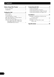
Contents Before Using This Product 2 In case of a set up with two units side by side 13 Specifications 14 1 Filter)/BPF (Band-Pass Filter) and LOW/HIGH Select Switch 4 Connecting the Unit 5 Connection Diagram 6 Connecting the Power Terminal 7 Connecting the Speaker Output Terminals ...... 8 ...
Contents Before Using This Product 2 In case of a set up with two units side by side 13 Specifications 14 1 Filter)/BPF (Band-Pass Filter) and LOW/HIGH Select Switch 4 Connecting the Unit 5 Connection Diagram 6 Connecting the Power Terminal 7 Connecting the Speaker Output Terminals ...... 8 ...
Owners Manual
Page 15
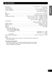
Use this value when working out total current drawn by this unit when an audio signal is input. ENGLISH ESPAÑOL DEUTSCH Specifications Power source ...14.4 V DC (10.8 - 15.1 V allowable) Grounding system ...Negative type Current consumption ...43.7 A (at continuous power, 4 Ω) Average... 9k Hz Cut off slope ...-12 dB/oct Maximum input level/impedance RCA: 6.5 V/22 kΩ (0.4 - 6.5 V) Note: • Specifications and the design are subject to possible modification without notice due to improvements. *Average current drawn • The average current drawn is nearly the maximum...
Use this value when working out total current drawn by this unit when an audio signal is input. ENGLISH ESPAÑOL DEUTSCH Specifications Power source ...14.4 V DC (10.8 - 15.1 V allowable) Grounding system ...Negative type Current consumption ...43.7 A (at continuous power, 4 Ω) Average... 9k Hz Cut off slope ...-12 dB/oct Maximum input level/impedance RCA: 6.5 V/22 kΩ (0.4 - 6.5 V) Note: • Specifications and the design are subject to possible modification without notice due to improvements. *Average current drawn • The average current drawn is nearly the maximum...

Service Manual
Page 1
.... MAR. 2000 Printed in Japan SCHEMATIC DIAGRAM 6 4. PIONEER EUROPE N.V. PCB CONNECTION DIAGRAM 12 5. CRT2482 X1R/UC,EW CONTENTS 1. SAFETY INFORMATION 2 2. ELECTRICAL PARTS LIST 18 6. Service PRS-X340/X1R/UC Manual BRIDGEABLE FOUR-CHANNEL POWER AMPLIFIER PRS-X340 ORDER NO. EXPLODED VIEWS AND PARTS LIST 2 3. OPERATIONS AND SPECIFICATIONS 26 PIONEER CORPORATION 4-1, Meguro 1-Chome, Meguro-ku, Tokyo 153-8654...
.... MAR. 2000 Printed in Japan SCHEMATIC DIAGRAM 6 4. PIONEER EUROPE N.V. PCB CONNECTION DIAGRAM 12 5. CRT2482 X1R/UC,EW CONTENTS 1. SAFETY INFORMATION 2 2. ELECTRICAL PARTS LIST 18 6. Service PRS-X340/X1R/UC Manual BRIDGEABLE FOUR-CHANNEL POWER AMPLIFIER PRS-X340 ORDER NO. EXPLODED VIEWS AND PARTS LIST 2 3. OPERATIONS AND SPECIFICATIONS 26 PIONEER CORPORATION 4-1, Meguro 1-Chome, Meguro-ku, Tokyo 153-8654...

Service Manual
Page 24
... and adjusting the indicated variable resistors to set VR502 to measure the voltage across Resistor R434 and set the required voltage range. PRS-X340 6. Setting Idle Current The following is performed with no loads on the outputs with no signal input. Notes: The Idle current...Setting the idle current to the following ranges will require you to Voltage Range. 3. Measure voltage across Resistor R435 and set VR501 to Voltage Range. Specification: Voltage Range: 45 mA ± 5mA 4.0 mV to Voltage Range. 4. ADJUSTMENT - Measure voltage across Resistor R433 and set VR503 to 5.0...
... and adjusting the indicated variable resistors to set VR502 to measure the voltage across Resistor R434 and set the required voltage range. PRS-X340 6. Setting Idle Current The following is performed with no loads on the outputs with no signal input. Notes: The Idle current...Setting the idle current to the following ranges will require you to Voltage Range. 3. Measure voltage across Resistor R435 and set VR501 to Voltage Range. Specification: Voltage Range: 45 mA ± 5mA 4.0 mV to Voltage Range. 4. ADJUSTMENT - Measure voltage across Resistor R433 and set VR503 to 5.0...

Service Manual
Page 26
OPERATIONS AND SPECIFICATIONS 8.1 OPERATIONS 26 PRS-X340 8.
OPERATIONS AND SPECIFICATIONS 8.1 OPERATIONS 26 PRS-X340 8.
Service Manual
Page 29
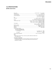
... value when working out total current drawn by this unit when an audio signal is nearly the maximum current drawn by multiple power amplifiers. 29 PRS-X340/X1R/UC Power source ...14.4 V DC (10.8 - 15.1 V allowable) Grounding system ...Negative type Current consumption ...43.7 A (at...Cut off slope ...-12 dB/oct Maximum input level/impedance RCA: 6.5 V/22 kΩ (0.4 - 6.5 V) Note: • Specifications and the design are subject to possible modification without notice due to improvements. *Average current drawn • The average current drawn is input. PRS-X340 8.2 SPECIFICATIONS -
... value when working out total current drawn by this unit when an audio signal is nearly the maximum current drawn by multiple power amplifiers. 29 PRS-X340/X1R/UC Power source ...14.4 V DC (10.8 - 15.1 V allowable) Grounding system ...Negative type Current consumption ...43.7 A (at...Cut off slope ...-12 dB/oct Maximum input level/impedance RCA: 6.5 V/22 kΩ (0.4 - 6.5 V) Note: • Specifications and the design are subject to possible modification without notice due to improvements. *Average current drawn • The average current drawn is input. PRS-X340 8.2 SPECIFICATIONS -

Service Manual
Page 30
PRS-X340/X1R/EW Power source ...14.4 V DC (10.8 - 15.1 V allowable) Grounding system ...Negative type Current consumption ...43.7 A (at continuous power, 4 Ω) Average current drawn* ...14.5 A (4 Ω ... slope ...-12 dB/oct Maximum input level/impedance RCA: 6.5 V/22 kΩ (0.4 - 6.5 V) Note: • Specifications and the design are subject to possible modification without notice due to improvements. *Average current drawn • The average current drawn is input. PRS-X340 - Use this unit when an audio signal is nearly the maximum current drawn by...
PRS-X340/X1R/EW Power source ...14.4 V DC (10.8 - 15.1 V allowable) Grounding system ...Negative type Current consumption ...43.7 A (at continuous power, 4 Ω) Average current drawn* ...14.5 A (4 Ω ... slope ...-12 dB/oct Maximum input level/impedance RCA: 6.5 V/22 kΩ (0.4 - 6.5 V) Note: • Specifications and the design are subject to possible modification without notice due to improvements. *Average current drawn • The average current drawn is input. PRS-X340 - Use this unit when an audio signal is nearly the maximum current drawn by...