Owner's Manual
Page 2
Contents o Safety & precautions o Mount diagrams o Parts List o Installing the mounting bracket o Installing the mount o Electrical o Securing the mounts o Additional security - 2 -
Contents o Safety & precautions o Mount diagrams o Parts List o Installing the mounting bracket o Installing the mount o Electrical o Securing the mounts o Additional security - 2 -
Owner's Manual
Page 3
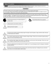
...plasma television and could cause a risk of the safety symbols and safety precautions, before beginning the installation. If installing the mount on other source of the wood stud before beginning installation. Use proper safety gear and tools for any other than wood ...injury or property damage. The installation instructions should be read and understood, including all times during the installation of the plasma. Mounting structure recommended wood studs, solid-flat concrete, and reinforced metal studs. Proper installation procedure by qualified personnel as outlined in plasma...
...plasma television and could cause a risk of the safety symbols and safety precautions, before beginning the installation. If installing the mount on other source of the wood stud before beginning installation. Use proper safety gear and tools for any other than wood ...injury or property damage. The installation instructions should be read and understood, including all times during the installation of the plasma. Mounting structure recommended wood studs, solid-flat concrete, and reinforced metal studs. Proper installation procedure by qualified personnel as outlined in plasma...
Owner's Manual
Page 4
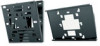
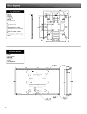
Mounting points (4.5") used on installations other than wall mounting. Mounting points for power or cables. C. D. Mount Diagrams TILT BACK PLATE PART#: 1.125 PSB-TBP MATERIAL: 12 (GA) CRS COLOR: Black powder coat A. Access hole for additional security screws. 1.000 1.750 1.250 19.771 16.000 5.460 2.865 e F 3.500 A d 8.000 18.500 5.000 4.500 8.000 b 3.250 4.500 5.460 16.000 c MOUNTING BRACKET PART#: Mounting bracket MATERIAL: 12 (GA) P & O COLOR: Black Powder coat - 4 - B. Lag bolt access slot.
Mounting points (4.5") used on installations other than wall mounting. Mounting points for power or cables. C. D. Mount Diagrams TILT BACK PLATE PART#: 1.125 PSB-TBP MATERIAL: 12 (GA) CRS COLOR: Black powder coat A. Access hole for additional security screws. 1.000 1.750 1.250 19.771 16.000 5.460 2.865 e F 3.500 A d 8.000 18.500 5.000 4.500 8.000 b 3.250 4.500 5.460 16.000 c MOUNTING BRACKET PART#: Mounting bracket MATERIAL: 12 (GA) P & O COLOR: Black Powder coat - 4 - B. Lag bolt access slot.

Owner's Manual
Page 5
Parts List HARDWARE LIST QTY 6 1 1 2 1 6 TOOLS NEEDED o Phillips screwdriver o Drill gun o Soft material or a blanket o Pencil o ¼" drill bit o Level o Measuring tape o Wrench with a 1/2" socket o Stud finder PCA-1 Ceiling adapter SIZE 5/16" Dia ƒ ƒ M6 x 12 (mm) Phillip security screws ƒ M8 x 20 Phillip screws DESCRIPTION Lag bolts Mounting bracket PSB-TBP tilt back plate Used for additional security on tilt mounts, mobile carts, floor stands and ceiling mounts Installations instructions Mount hardware PSA-1 Height adjustable ceiling adapter - 5 -
Parts List HARDWARE LIST QTY 6 1 1 2 1 6 TOOLS NEEDED o Phillips screwdriver o Drill gun o Soft material or a blanket o Pencil o ¼" drill bit o Level o Measuring tape o Wrench with a 1/2" socket o Stud finder PCA-1 Ceiling adapter SIZE 5/16" Dia ƒ ƒ M6 x 12 (mm) Phillip security screws ƒ M8 x 20 Phillip screws DESCRIPTION Lag bolts Mounting bracket PSB-TBP tilt back plate Used for additional security on tilt mounts, mobile carts, floor stands and ceiling mounts Installations instructions Mount hardware PSA-1 Height adjustable ceiling adapter - 5 -

Owner's Manual
Page 6
... to the holes on a flat and soft material such as outlined in serious personal injury and possible damage to the plasma display. Mounting bracket Mounting hardware (6) M8 x 10 Phillip screws Inverted plasma display - 6 - At least two (2) qualified personnel are fragile and heavy. ...See fig 1. Bottom of the plasma display before securing it on the plasma display. Installing the mounting bracket WARNING : Proper installation procedure by qualified personnel as (blankets, foam, cloth etc.) to prevent any damage to the plasma display. ...
... to the holes on a flat and soft material such as outlined in serious personal injury and possible damage to the plasma display. Mounting bracket Mounting hardware (6) M8 x 10 Phillip screws Inverted plasma display - 6 - At least two (2) qualified personnel are fragile and heavy. ...See fig 1. Bottom of the plasma display before securing it on the plasma display. Installing the mounting bracket WARNING : Proper installation procedure by qualified personnel as (blankets, foam, cloth etc.) to prevent any damage to the plasma display. ...
Owner's Manual
Page 7
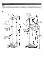
...marking 16" Wood studs behind the wall using a (commercially available) stud finder and mark the center of the studs when found. Installing the mounts Step 3 CAUTION: The plasma displays are centered before installing the back plate if not take proper measurements for the installation of this product. ...Locate the 16" wood stud centers behind the wall structure Adjusting the mount Tilt back plate CENTER OF VIEWING HEIGHT floor floor - 7 - See fig 3. Please verify that your installation requirements.
...marking 16" Wood studs behind the wall using a (commercially available) stud finder and mark the center of the studs when found. Installing the mounts Step 3 CAUTION: The plasma displays are centered before installing the back plate if not take proper measurements for the installation of this product. ...Locate the 16" wood stud centers behind the wall structure Adjusting the mount Tilt back plate CENTER OF VIEWING HEIGHT floor floor - 7 - See fig 3. Please verify that your installation requirements.

Owner's Manual
Page 8
...confirm the marks are located on wall Flat washers Tilt back plate Drill gun with a 1/4" drill bit Center of the studs. Confirm that the wall mount is still leveled and then screw a lag bolt to insure that the plasma display has enough power sources. - 8 - Put the lag bolt through ...the upper left and right slot openings on the wall mount. Drill 1/4" pilot holes on the six (6) markings on the mounting bracket. Next, using a pencil, mark the six (6) lag bolt slot openings on the wall.
...confirm the marks are located on wall Flat washers Tilt back plate Drill gun with a 1/4" drill bit Center of the studs. Confirm that the wall mount is still leveled and then screw a lag bolt to insure that the plasma display has enough power sources. - 8 - Put the lag bolt through ...the upper left and right slot openings on the wall mount. Drill 1/4" pilot holes on the six (6) markings on the mounting bracket. Next, using a pencil, mark the six (6) lag bolt slot openings on the wall.

Owner's Manual
Page 9
...Step 6 For additional security gradually tilt the bracket forward using a Phillips screwdriver. When all four (4) the tabs are interlocked with the way the plasma mount attaches to the desired angle. Caution: The plasma display is heavy and 2 people are needed to lift and install it . Secure the two (2) ...M6 x 12 (mm) Phillips screws (screws) see the interlocked tab. Failure to lift and install it . Failure to lock the mounts together. Align all four (4) tab openings to the tilt back plate receiving tabs and push the plasma as shown on the wall recheck all (4) tab...
...Step 6 For additional security gradually tilt the bracket forward using a Phillips screwdriver. When all four (4) the tabs are interlocked with the way the plasma mount attaches to the desired angle. Caution: The plasma display is heavy and 2 people are needed to lift and install it . Secure the two (2) ...M6 x 12 (mm) Phillips screws (screws) see the interlocked tab. Failure to lift and install it . Failure to lock the mounts together. Align all four (4) tab openings to the tilt back plate receiving tabs and push the plasma as shown on the wall recheck all (4) tab...


