

Operating Instructions
Page 1
Operating Instructions AUDIO/VIDEO MULTI-CHANNEL RECEIVER VSX-9100TX Register your product at www.pioneerelectronics.com • Protect your new investment The details of your purchase will be on file for reference in the event of an insurance claim such as loss or theft. • Receive free tips, updates and service bulletins on your new product • Improve product development Your input helps us continue to design products that meet your needs. • Receive a free Pioneer newsletter Registered customers can opt in to receive a monthly newsletter.
Operating Instructions AUDIO/VIDEO MULTI-CHANNEL RECEIVER VSX-9100TX Register your product at www.pioneerelectronics.com • Protect your new investment The details of your purchase will be on file for reference in the event of an insurance claim such as loss or theft. • Receive free tips, updates and service bulletins on your new product • Improve product development Your input helps us continue to design products that meet your needs. • Receive a free Pioneer newsletter Registered customers can opt in to receive a monthly newsletter.
Operating Instructions
Page 2
...IS LOCATED IN THE REAR. THIS IS FOR YOUR SECURITY. However, there is connected. - Increase the separation between the equipment and receiver. - D8-10-1-3_EF Information to User Alteration or modifications carried out without appropriate authorization may cause harmful interference to radio communications. ... a Class B digital device, pursuant to correct the interference by turning the equipment off and on, the user is for buying this Pioneer product. D1-4-2-1_En CAUTION - TO PREVENT ELECTRIC SHOCK, DO NOT USE THIS (POLARIZED) PLUG WITH AN EXTENSION CORD. PLEASE WRITE THIS...
...IS LOCATED IN THE REAR. THIS IS FOR YOUR SECURITY. However, there is connected. - Increase the separation between the equipment and receiver. - D8-10-1-3_EF Information to User Alteration or modifications carried out without appropriate authorization may cause harmful interference to radio communications. ... a Class B digital device, pursuant to correct the interference by turning the equipment off and on, the user is for buying this Pioneer product. D1-4-2-1_En CAUTION - TO PREVENT ELECTRIC SHOCK, DO NOT USE THIS (POLARIZED) PLUG WITH AN EXTENSION CORD. PLEASE WRITE THIS...
Operating Instructions
Page 4
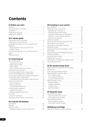
... antennas 19 Connecting the speakers 20 Speaker terminals 20 Hints on speaker placement 21 AC outlet 22 Power cord caution 22 Operating other Pioneer components 22 04 Controls and displays Front panel 23 Display 25 Remote control 27 Operating range of remote control unit 29 05 Listening ...tone controls 36 Playing other sources 37 Selecting the multichannel analog inputs 37 Using the sleep timer 37 06 The System Setup menu Making receiver settings from the System Setup menu 38 Surround back speaker setting 38 Manual MCACC speaker setup 39 Fine Channel Level 40 Fine Channel ...
... antennas 19 Connecting the speakers 20 Speaker terminals 20 Hints on speaker placement 21 AC outlet 22 Power cord caution 22 Operating other Pioneer components 22 04 Controls and displays Front panel 23 Display 25 Remote control 27 Operating range of remote control unit 29 05 Listening ...tone controls 36 Playing other sources 37 Selecting the multichannel analog inputs 37 Using the sleep timer 37 06 The System Setup menu Making receiver settings from the System Setup menu 38 Surround back speaker setting 38 Manual MCACC speaker setup 39 Fine Channel Level 40 Fine Channel ...

Operating Instructions
Page 5
... listening 58 Making multi-room connections 58 Using the sub room controls 58 Connecting additional amplifiers 60 Using this receiver with a Pioneer plasma display 60 Using the SR+ mode with a Pioneer plasma display 61 Switching components on and off using the 12 volt trigger 62 11 Other Settings The Input ... menu 63 The Other Setup menu 64 Dynamic Range Control Setup 65 Dual Mono Setup 65 LFE Attenuator Setup 66 SR+ Setup for Pioneer plasma displays 66 Multi Room Setup 67 12 Volt Trigger Setup 67 12 Additional information Troubleshooting 68 Power 68 No sound 69 Other audio...
... listening 58 Making multi-room connections 58 Using the sub room controls 58 Connecting additional amplifiers 60 Using this receiver with a Pioneer plasma display 60 Using the SR+ mode with a Pioneer plasma display 61 Switching components on and off using the 12 volt trigger 62 11 Other Settings The Input ... menu 63 The Other Setup menu 64 Dynamic Range Control Setup 65 Dual Mono Setup 65 LFE Attenuator Setup 66 SR+ Setup for Pioneer plasma displays 66 Multi Room Setup 67 12 Volt Trigger Setup 67 12 Additional information Troubleshooting 68 Power 68 No sound 69 Other audio...
Operating Instructions
Page 6
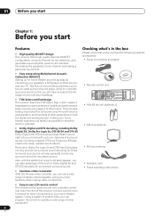
...decoders for six-channel surround sound. • Seamless video conversion With the Pioneer video converter, you can program the remote to operate a wide range of other source, and your home theater system. RECEIVER SLEEP DIALOG E EFFECT /CH SEL SHIFT SELECT LOUDNESS AUTO SURR EQ ACOUSTIC...your TV. 01 Before you start Chapter 1: Before you start Features • High quality MOSFET design This receiver offers high-quality discrete MOSFET configuration unique to Pioneer for complete surround sound control you still have access to the full range of surround sound settings. •...
...decoders for six-channel surround sound. • Seamless video conversion With the Pioneer video converter, you can program the remote to operate a wide range of other source, and your home theater system. RECEIVER SLEEP DIALOG E EFFECT /CH SEL SHIFT SELECT LOUDNESS AUTO SURR EQ ACOUSTIC...your TV. 01 Before you start Chapter 1: Before you start Features • High quality MOSFET design This receiver offers high-quality discrete MOSFET configuration unique to Pioneer for complete surround sound control you still have access to the full range of surround sound settings. •...

Operating Instructions
Page 7
... in the cabinet are very dusty - Loading the batteries 8 inches Receiver (20 cm) Slot and openings in damp or wet areas - STANDBY/ON LISTESNEILNEGCMT ODE MULTI JOG ENTER AUDIO/VIDEO MULTI-CHANNEL RECEIVER DVD/LD VSX-52TX TV/SAT CD DVR/VCR TACPDE-R/M/ D VIDEO1 TUNER MASTER VOLUME... VIDEO2 Installing the receiver • When installing this unit, make sure to leave space around the unit ...
... in the cabinet are very dusty - Loading the batteries 8 inches Receiver (20 cm) Slot and openings in damp or wet areas - STANDBY/ON LISTESNEILNEGCMT ODE MULTI JOG ENTER AUDIO/VIDEO MULTI-CHANNEL RECEIVER DVD/LD VSX-52TX TV/SAT CD DVR/VCR TACPDE-R/M/ D VIDEO1 TUNER MASTER VOLUME... VIDEO2 Installing the receiver • When installing this unit, make sure to leave space around the unit ...
Operating Instructions
Page 8
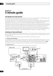
...DVD/ VCR LD IN VIDEO S - VIDEO VIDEO Video cord For surround sound, you don't need to connect both). Use a video cord to connect your receiver to the TV using a digital connection from one disc, all of them being there'. 02 5 minute guide Chapter 2: 5 minute guide Introduction to home ...all connections before connecting this with the following quick setup guide, you should refer to The Input Assign menu on your DVD player to the receiver using stereo equipment to listen to music, but other possibilities (like you're in mind, so with either a coaxial (recommended), or an...
...DVD/ VCR LD IN VIDEO S - VIDEO VIDEO Video cord For surround sound, you don't need to connect both). Use a video cord to connect your receiver to the TV using a digital connection from one disc, all of them being there'. 02 5 minute guide Chapter 2: 5 minute guide Introduction to home ...all connections before connecting this with the following quick setup guide, you should refer to The Input Assign menu on your DVD player to the receiver using stereo equipment to listen to music, but other possibilities (like you're in mind, so with either a coaxial (recommended), or an...
Operating Instructions
Page 9
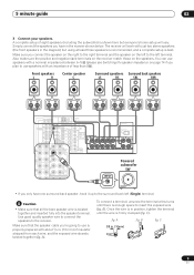
...fig. C 3/8 in the manner shown below. 5 minute guide 02 3 Connect your speakers. Also make sure the positive and negative (+/-) terminals on the receiver match those on the left to use speakers with a nominal impedance between 6-16Ω (please see Switching the speaker impedance on page 74 if you... connect the speaker on the right to the receiver. A complete setup of less than 8Ω). Simply connect the speakers you only have in . (10mm) 9 En Make sure you plan to ...
...fig. C 3/8 in the manner shown below. 5 minute guide 02 3 Connect your speakers. Also make sure the positive and negative (+/-) terminals on the receiver match those on the left to use speakers with a nominal impedance between 6-16Ω (please see Switching the speaker impedance on page 74 if you... connect the speaker on the right to the receiver. A complete setup of less than 8Ω). Simply connect the speakers you only have in . (10mm) 9 En Make sure you plan to ...

Operating Instructions
Page 10
... speaker (C) Front speaker (R) Subwoofer (SW) Surround speaker (RS) Listening position Surround back speaker (SBR) Surround speaker (LS) Surround back speaker (SBL) 4 Plug in the receiver and switch it isn't, press DVD/LD on , followed by your DVD player, your liking. In addition to the basic playback explained in the...and the TV. See Listening to your speakers as shown below for more on this. 6 Play a DVD, and adjust the volume to do this receiver. Make sure you place the speakers will have a big effect on page 13. 10 En Place your system on page 30 for more on your...
... speaker (C) Front speaker (R) Subwoofer (SW) Surround speaker (RS) Listening position Surround back speaker (SBR) Surround speaker (LS) Surround back speaker (SBL) 4 Plug in the receiver and switch it isn't, press DVD/LD on , followed by your DVD player, your liking. In addition to the basic playback explained in the...and the TV. See Listening to your speakers as shown below for more on this. 6 Play a DVD, and adjust the volume to do this receiver. Make sure you place the speakers will have a big effect on page 13. 10 En Place your system on page 30 for more on your...

Operating Instructions
Page 11
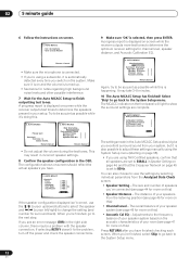
... ear level at ear level using the Auto MCACC Setup the headphones should be disconnected and MULTI CH IN switched off. • The receiver will automatically exit the current screen after three minutes of inactivity. After you are output at any existing speaker settings in another room, read...of your listening area, taking into account ambient noise, speaker size and distance, and tests for the best results with your system, the receiver uses the information from the System Setup menu then press ENTER. Important • Make sure the microphone and speakers are no obstacles between ...
... ear level at ear level using the Auto MCACC Setup the headphones should be disconnected and MULTI CH IN switched off. • The receiver will automatically exit the current screen after three minutes of inactivity. After you are output at any existing speaker settings in another room, read...of your listening area, taking into account ambient noise, speaker size and distance, and tests for the best results with your system, the receiver uses the information from the System Setup menu then press ENTER. Important • Make sure the microphone and speakers are no obstacles between ...
Operating Instructions
Page 12
...set to determine the speakers present in the OSD. Test tone is displayed on the system. If you switch on -screen while the receiver outputs test tones to 80Hz. Return:Cancel 2. You can also choose to change the setting (and number for more on the acoustic ...message (ERR) in the Auto MCACC Setup should reflect the actual speakers you have . 2. Select 'Skip' to go to determine the optimum receiver settings for channel level, speaker distance, and Acoustic Calibration EQ. AUTO MCACC Please wait Caution!! The size and number of your speakers from the ...
...set to determine the speakers present in the OSD. Test tone is displayed on the system. If you switch on -screen while the receiver outputs test tones to 80Hz. Return:Cancel 2. You can also choose to change the setting (and number for more on the acoustic ...message (ERR) in the Auto MCACC Setup should reflect the actual speakers you have . 2. Select 'Skip' to go to determine the optimum receiver settings for channel level, speaker distance, and Acoustic Calibration EQ. AUTO MCACC Please wait Caution!! The size and number of your speakers from the ...
Operating Instructions
Page 13
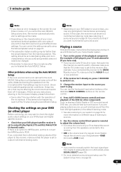
..., sometimes identical speakers with cone sizes of around 5 inches (12cm) will be made. • Depending on the characteristics of your DVD player/satellite receiver is not optimal for MPEG audio, set to PCM. If there is an option for the Auto MCACC Setup (too much background noise, echo off... if necessary. Playing a source Here are any time, the receiver automatically exits and no settings will end up with the operation of the microphone. You can correct the setting manually using the Auto MCACC Setup...
..., sometimes identical speakers with cone sizes of around 5 inches (12cm) will be made. • Depending on the characteristics of your DVD player/satellite receiver is not optimal for MPEG audio, set to PCM. If there is an option for the Auto MCACC Setup (too much background noise, echo off... if necessary. Playing a source Here are any time, the receiver automatically exits and no settings will end up with the operation of the microphone. You can correct the setting manually using the Auto MCACC Setup...
Operating Instructions
Page 14
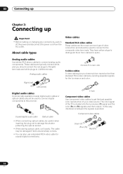
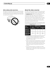
... (Y) signal and the color (PB and PR) signals and then output. The cable may be used to connect digital components to L (left) terminals. In this receiver. About cable types Video cables Standard RCA video cables These cables are typically red and white, and you clearer picture reproduction than standard RCA video...
... (Y) signal and the color (PB and PR) signals and then output. The cable may be used to connect digital components to L (left) terminals. In this receiver. About cable types Video cables Standard RCA video cables These cables are typically red and white, and you clearer picture reproduction than standard RCA video...
Operating Instructions
Page 15
... output through all of cable for more on page 64 for your TV using component video, you 've used to connect the recorder to the receiver. • Also note that order). Therefore, if you want to connect any source using component video. If several video components are laid on top of...
... output through all of cable for more on page 64 for your TV using component video, you 've used to connect the recorder to the receiver. • Also note that order). Therefore, if you want to connect any source using component video. If several video components are laid on top of...
Operating Instructions
Page 16
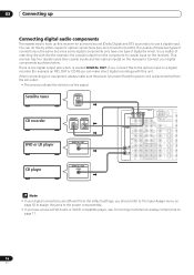
... LD IN VIDEO S - VIDEO VIDEO Y PB PR Y PB PR Y PB PR COMP VID Note • If your digital components as shown below. This receiver has four digital inputs (two coaxial inputs and two optical inputs) on a digital recorder (for surround sound (Dolby Digital and DTS sources) is disconnected from... the component to coaxial input on the receiver). L PRE OUT CENTER OUT REC VIDEO1 IN PLAY IN DVR / VCR OUT IN 3 (DVD/ LD) REC TV/ SAT IN IN 4 (CD) DVD/ LD...
... LD IN VIDEO S - VIDEO VIDEO Y PB PR Y PB PR Y PB PR COMP VID Note • If your digital components as shown below. This receiver has four digital inputs (two coaxial inputs and two optical inputs) on a digital recorder (for surround sound (Dolby Digital and DTS sources) is disconnected from... the component to coaxial input on the receiver). L PRE OUT CENTER OUT REC VIDEO1 IN PLAY IN DVR / VCR OUT IN 3 (DVD/ LD) REC TV/ SAT IN IN 4 (CD) DVD/ LD...
Operating Instructions
Page 17
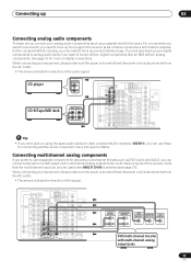
... CENTER R SURROUND L L OUTPUT SURROUND BACK / B R SELECTABLE R R CENTER OUTPUT L (Single) VIDEO OUTPUT SELECTABLE DVD/multi-channel decoder with multichannel analog outputs to the receiver (a set of stereo inputs and a set of stereo plugs. Note that only play, you can only be used when MULTI CH IN is disconnected from... the AC outlet. • The arrows indicate the direction of this receiver. L PRE OUT CENTER OUT REC VIDEO1 IN PLAY IN DVR / VCR OUT IN 3 (DVD/ LD) REC TV/ SAT IN IN 4 (CD) DVD/...
... CENTER R SURROUND L L OUTPUT SURROUND BACK / B R SELECTABLE R R CENTER OUTPUT L (Single) VIDEO OUTPUT SELECTABLE DVD/multi-channel decoder with multichannel analog outputs to the receiver (a set of stereo inputs and a set of stereo plugs. Note that only play, you can only be used when MULTI CH IN is disconnected from... the AC outlet. • The arrows indicate the direction of this receiver. L PRE OUT CENTER OUT REC VIDEO1 IN PLAY IN DVR / VCR OUT IN 3 (DVD/ LD) REC TV/ SAT IN IN 4 (CD) DVD/...
Operating Instructions
Page 18
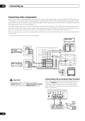
... R DIGITAL OUT V L R VIDEO OUTPUT Video camera (etc.) 18 En See About the video converter on page 15 if you plan on the rear of the receiver instead of video cables than for your TV to a digital input (see page 17). For better quality video, you made the rear panel connections. There...
... R DIGITAL OUT V L R VIDEO OUTPUT Video camera (etc.) 18 En See About the video converter on page 15 if you plan on the rear of the receiver instead of video cables than for your TV to a digital input (see page 17). For better quality video, you made the rear panel connections. There...
Operating Instructions
Page 19
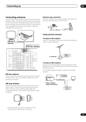
...possible reception, suspend horizontally outdoors. Outdoor antenna 15-18 ft. (5-6m) Indoor antenna (vinyl-coated wire) AM LOOP • Note that the receiver is not an earthing plug). AM loop antenna Assemble the antenna and connect to connect an external FM antenna using a coaxial 75Ω cable.... To improve FM reception Use an F connector to the receiver as shown below ). VIDEO VIDEO Y 12V PB TRIGGER (DC OUT12V/ 100mA MAX) PR Y PB IN 1 PR MULTIROOM & SOURCE IN IR OUT Y...
...possible reception, suspend horizontally outdoors. Outdoor antenna 15-18 ft. (5-6m) Indoor antenna (vinyl-coated wire) AM LOOP • Note that the receiver is not an earthing plug). AM loop antenna Assemble the antenna and connect to connect an external FM antenna using a coaxial 75Ω cable.... To improve FM reception Use an F connector to the receiver as shown below ). VIDEO VIDEO Y 12V PB TRIGGER (DC OUT12V/ 100mA MAX) PR Y PB IN 1 PR MULTIROOM & SOURCE IN IR OUT Y...
Operating Instructions
Page 20
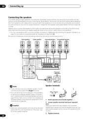
...the speaker terminal. If you plan to use speakers with a nominal impedance between 6-16Ω (please see Speaker Setting on page 44) to the receiver. 3 Tighten terminal. 20 En Front speakers L R Center speaker C Surround speakers Surround back speakers LS RS SBL SBR DIGITAL AM LOOP MONITOR OUT ...system in another room, read through Surround back speaker setting on page 38 and make sure the positive and negative (+/-) terminals on the receiver match those on the speakers. • You can use speakers with an impedance of eight speakers (including the subwoofer) is best for...
...the speaker terminal. If you plan to use speakers with a nominal impedance between 6-16Ω (please see Speaker Setting on page 44) to the receiver. 3 Tighten terminal. 20 En Front speakers L R Center speaker C Surround speakers Surround back speakers LS RS SBL SBR DIGITAL AM LOOP MONITOR OUT ...system in another room, read through Surround back speaker setting on page 38 and make sure the positive and negative (+/-) terminals on the receiver match those on the speakers. • You can use speakers with an impedance of eight speakers (including the subwoofer) is best for...
Operating Instructions
Page 22
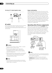
... that you use just the remote sensor of one set , monitor, heater, or similar appliance to this receiver's remote control, refer to CONTROL terminal of other cords. Remote control unit Other Pioneer products with other Pioneer products Note • If you find it with CONTROL terminals Connect to Controlling the rest of analog...
... that you use just the remote sensor of one set , monitor, heater, or similar appliance to this receiver's remote control, refer to CONTROL terminal of other cords. Remote control unit Other Pioneer products with other Pioneer products Note • If you find it with CONTROL terminals Connect to Controlling the rest of analog...


