User Guide
Page 5
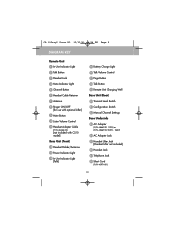
...5 Channel Button 6 Headset Cable Retainer 7 Antenna 8 Ringer ON/OFF [for use with optional Lifter] 9 Mute Button 10 Listen Volume Control 11 Headset Adapter Cable (P/N 43446-02) [not included with CS10 model] Base Unit (Front) 12 Headset Holder/Antenna 13 Power Indicator Light 14 In-Use Indicator Light... Well Base Unit (Rear) 20 Transmit Level Switch 21 Configuration Switch 22 Manual Channel Settings Base Underside 23 AC Adapter (P/N 45669-01 120V) or (P/N 45669-02 220V - 240V) 24 AC Adapter Jack 25 Handset Lifter Jack [Handset Lifter not included] 26 Handset Jack 27 Telephone Jack 28 Short Cord...
...5 Channel Button 6 Headset Cable Retainer 7 Antenna 8 Ringer ON/OFF [for use with optional Lifter] 9 Mute Button 10 Listen Volume Control 11 Headset Adapter Cable (P/N 43446-02) [not included with CS10 model] Base Unit (Front) 12 Headset Holder/Antenna 13 Power Indicator Light 14 In-Use Indicator Light... Well Base Unit (Rear) 20 Transmit Level Switch 21 Configuration Switch 22 Manual Channel Settings Base Underside 23 AC Adapter (P/N 45669-01 120V) or (P/N 45669-02 220V - 240V) 24 AC Adapter Jack 25 Handset Lifter Jack [Handset Lifter not included] 26 Handset Jack 27 Telephone Jack 28 Short Cord...
User Guide
Page 10
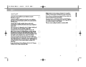
...ÇAIS ESPAN˜ OL PORTUGUEˆS KOREAN JAPANESE CHINESE CA 10Gray2 Body.r2 12/12/01 6:50 PM Page 6 STEP 1 SETUP Connect the CA10 Amplifier to your telephone base and insert into the Handset Jack 26 on page ii. Unplug the telephone handset from the Base. The Power LED... In-Use Indicator Light 14 will need the QD to the AC Adapter Jack 24 and into the Retainer 6 . You are using the G illustrations on the underside of the CA10 Base Unit. Do not force. Now connect the AC Adapter 23 to 2.5mm Headset Adapter Cable 11 (P/N 43446-02). If you are now ready to ...
...ÇAIS ESPAN˜ OL PORTUGUEˆS KOREAN JAPANESE CHINESE CA 10Gray2 Body.r2 12/12/01 6:50 PM Page 6 STEP 1 SETUP Connect the CA10 Amplifier to your telephone base and insert into the Handset Jack 26 on page ii. Unplug the telephone handset from the Base. The Power LED... In-Use Indicator Light 14 will need the QD to the AC Adapter Jack 24 and into the Retainer 6 . You are using the G illustrations on the underside of the CA10 Base Unit. Do not force. Now connect the AC Adapter 23 to 2.5mm Headset Adapter Cable 11 (P/N 43446-02). If you are now ready to ...

User Guide
Page 12
...Remote Unit. A Return the Remote to C re-establish a communication link. Adjust headset so the voice boom is closer to the Base via the AC Power Adapter. On only when transmit audio is applied to your Remote Battery Pack is low, heard only through the headset. Red LED. Charge - Remains steady... A DIAL TONE Make sure your mouth. 11 ENGLISH FRANÇAIS ESPAN˜ OL PORTUGUEˆS KOREAN JAPANESE CHINESE A Remove and replace the AC power cord from the Base Unit. On only when Remote or Base Unit TALK button is off. Red LED. Check that Handset and Telephone cords...
...Remote Unit. A Return the Remote to C re-establish a communication link. Adjust headset so the voice boom is closer to the Base via the AC Power Adapter. On only when transmit audio is applied to your Remote Battery Pack is low, heard only through the headset. Red LED. Charge - Remains steady... A DIAL TONE Make sure your mouth. 11 ENGLISH FRANÇAIS ESPAN˜ OL PORTUGUEˆS KOREAN JAPANESE CHINESE A Remove and replace the AC power cord from the Base Unit. On only when Remote or Base Unit TALK button is off. Red LED. Check that Handset and Telephone cords...