
User Manual
Page 2
... engine (motor), remove the wire from the spark plug, thoroughly inspect the tiller for proper tightness to be sure the equipment is to a running (except where specifically extended period. A WARNING a The engine exhaust from the plug to prevent accidental starting when setting up spilled fuel before storing in any adjustments while the important details if the tiller is to cause cancer, birth defects, or other bolts at high speeds...
... engine (motor), remove the wire from the spark plug, thoroughly inspect the tiller for proper tightness to be sure the equipment is to a running (except where specifically extended period. A WARNING a The engine exhaust from the plug to prevent accidental starting when setting up spilled fuel before storing in any adjustments while the important details if the tiller is to cause cancer, birth defects, or other bolts at high speeds...
User Manual
Page 3
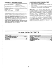
... SPECIFICATIONS ASSEMBLY OPERATION 2 3,12-14 3 4-6 7-11 MAINTENANCE SCHEDULE SERVICE & ADJUSTMENTS STORAGE TROUBLESHOOTING REPAIR PARTS-TILLER WARRANTY 12 14-17 18 19 20-26 27 3 Should you experience any problems you to assemble and maintain your nearest authorized service center. Please read and retain this Owner's Manual. IMPORTANT: THIS UNIT IS EQUIPPED WITH AN INTERNAL COMBUSTION ENGINE AND SHOULD NOT BE USED ON OR NEAR ANY UNIMPROVED FORESTCOVERED, BRUSH-COVERED OR GRASS COVERED...
... SPECIFICATIONS ASSEMBLY OPERATION 2 3,12-14 3 4-6 7-11 MAINTENANCE SCHEDULE SERVICE & ADJUSTMENTS STORAGE TROUBLESHOOTING REPAIR PARTS-TILLER WARRANTY 12 14-17 18 19 20-26 27 3 Should you experience any problems you to assemble and maintain your nearest authorized service center. Please read and retain this Owner's Manual. IMPORTANT: THIS UNIT IS EQUIPPED WITH AN INTERNAL COMBUSTION ENGINE AND SHOULD NOT BE USED ON OR NEAR ANY UNIMPROVED FORESTCOVERED, BRUSH-COVERED OR GRASS COVERED...
User Manual
Page 4
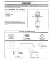
.../32 x 1 x 11 Gauge (1) Handle Lock Lever (1) Hairpin Clip ■ 11 111 (1) Pivot Bolt 3/8-16 UNC Grade 5 cz, Extra Shear Pins & Clips 4 ASSEMBLY Your new tiller has been assembled at the factory with exception of pliers (1) 9/16" wrench FRONT LEFT RIGHT OPERATOR'S POSITION (See Fig. 1) When right orleft hand is mentionedin this manual, it means when you assemble must be tightened securely. Usethe correct tools as necessary...
.../32 x 1 x 11 Gauge (1) Handle Lock Lever (1) Hairpin Clip ■ 11 111 (1) Pivot Bolt 3/8-16 UNC Grade 5 cz, Extra Shear Pins & Clips 4 ASSEMBLY Your new tiller has been assembled at the factory with exception of pliers (1) 9/16" wrench FRONT LEFT RIGHT OPERATOR'S POSITION (See Fig. 1) When right orleft hand is mentionedin this manual, it means when you assemble must be tightened securely. Usethe correct tools as necessary...

User Manual
Page 5
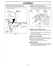
...; With handle assembly in lowest position, securely tighten handle lock lever by rotating clockwise. SIDE OF TILLER 0 0 HANDLE ASSEMBLY GEARCASE NOTCH HANDLE LOCK • Grasp handle assembly. Be sure handle lock remains in front part of plate and tighten. • Cut down remaining corners of cartoning material. Tighten nut on L.H. Leaving handle assembly in lowest position will allow for easier adjustment. • Place fiat washer on smooth side of handle lock lever. • Inserthandlelockleverthroughhandlebaseandgearcase. Screw in...
...; With handle assembly in lowest position, securely tighten handle lock lever by rotating clockwise. SIDE OF TILLER 0 0 HANDLE ASSEMBLY GEARCASE NOTCH HANDLE LOCK • Grasp handle assembly. Be sure handle lock remains in front part of plate and tighten. • Cut down remaining corners of cartoning material. Tighten nut on L.H. Leaving handle assembly in lowest position will allow for easier adjustment. • Place fiat washer on smooth side of handle lock lever. • Inserthandlelockleverthroughhandlebaseandgearcase. Screw in...
User Manual
Page 6
...; Rotate tiller handle to the right and pull tiller out of this manual). 6 Correct and equal tire pressure is in control bar bracket if necessary. ENO OF CLUTCH CABLE CONTROL BAR BRACKET CONNECT SHIFT ROD (See Fig. 7) • Insert end of shift rod into hole of shift lever indicator. • Insert hairpin clip through hole in "N" position (See Fig. 7) • Tilt tiller forward by lifting handle. ASSEMBLY ATTACH CLUTCH CABLE...
...; Rotate tiller handle to the right and pull tiller out of this manual). 6 Correct and equal tire pressure is in control bar bracket if necessary. ENO OF CLUTCH CABLE CONTROL BAR BRACKET CONNECT SHIFT ROD (See Fig. 7) • Insert end of shift rod into hole of shift lever indicator. • Insert hairpin clip through hole in "N" position (See Fig. 7) • Tilt tiller forward by lifting handle. ASSEMBLY ATTACH CLUTCH CABLE...

User Manual
Page 7
... OFF FAST SLOW CHOKE FUEL OIL RUN STOP O SHIFT LEVER THROTTLE CONTROL O O DRIVE CONTROL BAR CHOKE CONTROL SHIFT LEVER INDICATOR I O 0 DEPTH STAKE O LEVELING SHIELD. OUTER SIDE SHIELD 0 RECOIL STARTER HANDLE FIG. 8 MEETS ANSI SAFETY REQUIREMENTS Our tillers conform to the safety standards of various controls and adjustments. Adjustable to start the engine. Used to control engine speed. SHIFT LEVER INDICATOR - DEPTH STAKE - OUTER SIDE SHIELD - Used to shift transmission gears. OPERATION KNOW YOUR TILLER READ THIS OWNER'S MANUAL AND SAFETY RULES BEFORE...
... OFF FAST SLOW CHOKE FUEL OIL RUN STOP O SHIFT LEVER THROTTLE CONTROL O O DRIVE CONTROL BAR CHOKE CONTROL SHIFT LEVER INDICATOR I O 0 DEPTH STAKE O LEVELING SHIELD. OUTER SIDE SHIELD 0 RECOIL STARTER HANDLE FIG. 8 MEETS ANSI SAFETY REQUIREMENTS Our tillers conform to the safety standards of various controls and adjustments. Adjustable to start the engine. Used to control engine speed. SHIFT LEVER INDICATOR - DEPTH STAKE - OUTER SIDE SHIELD - Used to shift transmission gears. OPERATION KNOW YOUR TILLER READ THIS OWNER'S MANUAL AND SAFETY RULES BEFORE...
User Manual
Page 9
... capacity see "PRODUCT SPECIFICATIONS" on page 3 of this manual. To change oil for easier starting (See oil viscosity chart in the fuel tank or permanent damage may occur. OIL LEVEL I . Tines will take extra pulls of fuel, it run out of the recoil starter to move fuel from the tank to the engine. • Make sure spark plug wire is properly connected. 9 • Move shift lever indicator to "N" (neutral) position. If gasoline is level. CHECK ENGINE OIL LEVEL...
... capacity see "PRODUCT SPECIFICATIONS" on page 3 of this manual. To change oil for easier starting (See oil viscosity chart in the fuel tank or permanent damage may occur. OIL LEVEL I . Tines will take extra pulls of fuel, it run out of the recoil starter to move fuel from the tank to the engine. • Make sure spark plug wire is properly connected. 9 • Move shift lever indicator to "N" (neutral) position. If gasoline is level. CHECK ENGINE OIL LEVEL...
User Manual
Page 10
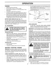
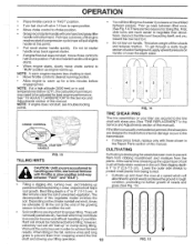
... tiller. Do not let starter handle snap back against starter. • If engine fires but does not start of compression cycle (rope will pull slightly harder at the end of the growing season to the transmission. • If shear pin(s) break, replace only with throttle in slow position (mid-way between "FAST" and "IDLE"). • Tilling is destroying the weeds between passes. See "TO ADJUST CARBURETOR" in the Service and Adjustments...
... tiller. Do not let starter handle snap back against starter. • If engine fires but does not start of compression cycle (rope will pull slightly harder at the end of the growing season to the transmission. • If shear pin(s) break, replace only with throttle in slow position (mid-way between "FAST" and "IDLE"). • Tilling is destroying the weeds between passes. See "TO ADJUST CARBURETOR" in the Service and Adjustments...
User Manual
Page 12
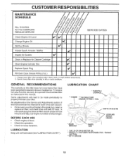
CUSTOMER RESPONSIBILITIES MAINTENANCE SCHEDULE FILL IN DATES AS YOU COMPLETE REGULAR SERVICE
CUSTOMER RESPONSIBILITIES MAINTENANCE SCHEDULE FILL IN DATES AS YOU COMPLETE REGULAR SERVICE

User Manual
Page 13
... "CHECK ENGINE OIL LEVEL" in cold weather, these multi-viscosity oils will not run properly using a stiff-bristled brush. • Remove blower housing and clean as contact may cause burns. Service paper cartridge every 100 hours of this manual. TO SERVICE CARTRIDGE • Carefully remove cartridge to drain oil. • After oil has drained completely, replace oil drain plug and tighten securely. • Remove oil filler plug. Clean base carefully to prevent accidental starting in the Operation section of operation or...
... "CHECK ENGINE OIL LEVEL" in cold weather, these multi-viscosity oils will not run properly using a stiff-bristled brush. • Remove blower housing and clean as contact may cause burns. Service paper cartridge every 100 hours of this manual. TO SERVICE CARTRIDGE • Carefully remove cartridge to drain oil. • After oil has drained completely, replace oil drain plug and tighten securely. • Remove oil filler plug. Clean base carefully to prevent accidental starting in the Operation section of operation or...
User Manual
Page 14
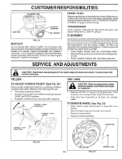
... wheels free of tire pressure. O N ,11,13:c2- If your tilling conditions. TILLER TO ADJUST HANDLE HEIGHT (See Fig. 22) Select handle height best suited for cleaning and inspection. SPARK PLUG Replace spark plugs at different settings between "HIGH" and "LOW" positions. • Retighten handle lock lever securely after every 50 hours of EP #1 grease. ir CLEVIS PIN 1 FIG. 22 • HAIRPIN CLIP 14 FIG. 23 SERVICE AND ADJUSTMENTS a CAUTION: Disconnect spark plug wire from wheel. • Remove wheel...
... wheels free of tire pressure. O N ,11,13:c2- If your tilling conditions. TILLER TO ADJUST HANDLE HEIGHT (See Fig. 22) Select handle height best suited for cleaning and inspection. SPARK PLUG Replace spark plugs at different settings between "HIGH" and "LOW" positions. • Retighten handle lock lever securely after every 50 hours of EP #1 grease. ir CLEVIS PIN 1 FIG. 22 • HAIRPIN CLIP 14 FIG. 23 SERVICE AND ADJUSTMENTS a CAUTION: Disconnect spark plug wire from wheel. • Remove wheel...

User Manual
Page 16
... while the drive control bar is in groove of belt guard (located behind wheel). • Pull belt guard out and away from unit. • Replace belt guard by reversing above procedure. Pull wheel outfrom tiller about 1 inch (2.5 cm). • Remove two (2) screws from side of belt guard. • Remove hex nut and washer from left wheel. SERVICE AND ADJUSTMENTS TO REMOVE BELT GUARD (See Fig. 27) NOTE: For ease of removal, remove hairpin clip and clevis pin from bottom of transmission pulley and into engine pulley.
... while the drive control bar is in groove of belt guard (located behind wheel). • Pull belt guard out and away from unit. • Replace belt guard by reversing above procedure. Pull wheel outfrom tiller about 1 inch (2.5 cm). • Remove two (2) screws from side of belt guard. • Remove hex nut and washer from left wheel. SERVICE AND ADJUSTMENTS TO REMOVE BELT GUARD (See Fig. 27) NOTE: For ease of removal, remove hairpin clip and clevis pin from bottom of transmission pulley and into engine pulley.
User Manual
Page 17
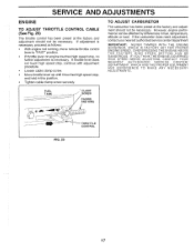
FUEL TANK CLAMP SCREW CASING AND WIRE FIG. 29 THROTTLE CONTROL 17 If throttle lever does not touch high speed stop, continue with adjustment procedure. • Loosen cable clamp screw. • Move throttle lever up until it touches high speed stop , no further adjustment is necessary. OVERSPEEDING THE ENGINE ABOVE THE FACTORY HIGH SPEED SETTING CAN BE DANGEROUS. If adjustment is necessary, proceed as follows: • With engine not running, move remote throttle control lever to "FAST" position. • If...
FUEL TANK CLAMP SCREW CASING AND WIRE FIG. 29 THROTTLE CONTROL 17 If throttle lever does not touch high speed stop, continue with adjustment procedure. • Loosen cable clamp screw. • Move throttle lever up until it touches high speed stop , no further adjustment is necessary. OVERSPEEDING THE ENGINE ABOVE THE FACTORY HIGH SPEED SETTING CAN BE DANGEROUS. If adjustment is necessary, proceed as follows: • With engine not running, move remote throttle control lever to "FAST" position. • If...
User Manual
Page 18
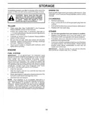
... drain the gas tank and carburetor if using fuel stabilizer. CYLINDER(S) • Remove spark plug. • Pour 1 ounce (29 ml) of oil through spark plug hole into cylinder. • Pull starter handle slowly several times to distribute oil. • Replace with clean oil. (See "ENGINE" in your gasoline will cause problems. • If possible, store your unit indoors and cover it run until the fuel lines and carburetor are securely fastened. Replace if necessary. • Touch up all nuts, bolts...
... drain the gas tank and carburetor if using fuel stabilizer. CYLINDER(S) • Remove spark plug. • Pour 1 ounce (29 ml) of oil through spark plug hole into cylinder. • Pull starter handle slowly several times to distribute oil. • Replace with clean oil. (See "ENGINE" in your gasoline will cause problems. • If possible, store your unit indoors and cover it run until the fuel lines and carburetor are securely fastened. Replace if necessary. • Touch up all nuts, bolts...
User Manual
Page 19
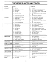
.... Check oil level/change oil. 2. Clean engine air screen. 3. Dirty air cleaner. 3. Engine is not engaged. 2. Dirty engine air screen. 11. Dirty/clogged muffler. 12. Fill fuel tank. 2. Drain fuel tank and carburetor, and refill tank with fresh gasoline. 7. Drain fuel tank and refill with fresh gasoline. 6. Contact an authorized service center/department. 1. Loose spark plug wire. 6. See "TO START ENGINE" in "FAST" position. 2. Replace spark plug or adjust gap. 9. Place throttle control in Operation section. 3. Clean or replace air cleaner cartridge. 3. Clean engine air screen...
.... Check oil level/change oil. 2. Clean engine air screen. 3. Dirty air cleaner. 3. Engine is not engaged. 2. Dirty engine air screen. 11. Dirty/clogged muffler. 12. Fill fuel tank. 2. Drain fuel tank and carburetor, and refill tank with fresh gasoline. 7. Drain fuel tank and refill with fresh gasoline. 6. Contact an authorized service center/department. 1. Loose spark plug wire. 6. See "TO START ENGINE" in "FAST" position. 2. Replace spark plug or adjust gap. 9. Place throttle control in Operation section. 3. Clean or replace air cleaner cartridge. 3. Clean engine air screen...

User Manual
Page 20
... 150217 Handle 26 159232 Cable, Clutch 29 73731000 Nut, Keps #10-24 UNC 31 150696 Bolt, Pivot 34 145821 Bracket, Clutch Cable 35 146480 Grommet, Handle 36 126949X428 Bracket, Handle 37 102604X Grip, Bar Control 38 73800500 Locknut 5/16-18 39 10040500 Washer, Lock 5/16 42 121248X Bushing, Snap NOTE: All component dimensions given in U.S. NO. Lever, Lock, Handle 19 1 cS; 20 31 KEY PART NO. REPAIR PARTS TILLER - - inches. 1 inch...
... 150217 Handle 26 159232 Cable, Clutch 29 73731000 Nut, Keps #10-24 UNC 31 150696 Bolt, Pivot 34 145821 Bracket, Clutch Cable 35 146480 Grommet, Handle 36 126949X428 Bracket, Handle 37 102604X Grip, Bar Control 38 73800500 Locknut 5/16-18 39 10040500 Washer, Lock 5/16 42 121248X Bushing, Snap NOTE: All component dimensions given in U.S. NO. Lever, Lock, Handle 19 1 cS; 20 31 KEY PART NO. REPAIR PARTS TILLER - - inches. 1 inch...

User Manual
Page 21
..., Lock 3/8 Nut, Hex 3/8-16 Shield, Inner Belt Guard Screw, Shift Lever Lever, Shift Bolt, Carriage 1/4-20 x 1/2 Gr. 5 Plate, Shift Indicator Screw, Hex, Washer Head, Slotted #10-24x 1/2 Clip Washer, Lock 1/4 Nut, Hex 1/4-20 Screw, Set, Hex 5/16-18 x 3/8 Spacer, Split 0.327 x 0.42 x 1.220 Washer 11/32 x 11/16 x 16 Ga. H. inches. 1 inch = 25.4 mm 21 NO. Hex 5/16-18 x 1-1/2 Bracket, Reinforcement, L. Bolt. REPAIR PARTS TILLER - - Sheave, Engine Bolt, Fin Hx 5/16-18 x 2-3/4 Cap, Plunger Screw...
..., Lock 3/8 Nut, Hex 3/8-16 Shield, Inner Belt Guard Screw, Shift Lever Lever, Shift Bolt, Carriage 1/4-20 x 1/2 Gr. 5 Plate, Shift Indicator Screw, Hex, Washer Head, Slotted #10-24x 1/2 Clip Washer, Lock 1/4 Nut, Hex 1/4-20 Screw, Set, Hex 5/16-18 x 3/8 Spacer, Split 0.327 x 0.42 x 1.220 Washer 11/32 x 11/16 x 16 Ga. H. inches. 1 inch = 25.4 mm 21 NO. Hex 5/16-18 x 1-1/2 Bracket, Reinforcement, L. Bolt. REPAIR PARTS TILLER - - Sheave, Engine Bolt, Fin Hx 5/16-18 x 2-3/4 Cap, Plunger Screw...

User Manual
Page 22
... 795R 15 16 7192J Tire Rim Tire Valve Engine, Briggs Model 110402 (Order parts from engine manufacturer) Tie Cable NOTE: All component dimensions given in U.S. ". ...."' 2 ',.. 1 411\ ss.•, k. " „., Ni,s..,.-i.."-.4.. .14 ,-,----- .75 / ".A., _,* 1 ,,,.. .„. kt .„ . inches. 1 inch = 25.4 mm 22 MODEL NUMBER HDR500K MAINFRAME, RIGHT SIDE 16 0 z 0 .., .....4.7 15 O ---. Washer, Lock 3/8 Nut, Hex 3/8-16 Bolt, Hex 5/16-18 x 1-1/2 Clip, Hairpin Rivet, Drilled KEY PART NO. REPAIR PARTS TILLER - - k 7 \ \ \ k . .. . ..... 0 I ,I,ifi...
... 795R 15 16 7192J Tire Rim Tire Valve Engine, Briggs Model 110402 (Order parts from engine manufacturer) Tie Cable NOTE: All component dimensions given in U.S. ". ...."' 2 ',.. 1 411\ ss.•, k. " „., Ni,s..,.-i.."-.4.. .14 ,-,----- .75 / ".A., _,* 1 ,,,.. .„. kt .„ . inches. 1 inch = 25.4 mm 22 MODEL NUMBER HDR500K MAINFRAME, RIGHT SIDE 16 0 z 0 .., .....4.7 15 O ---. Washer, Lock 3/8 Nut, Hex 3/8-16 Bolt, Hex 5/16-18 x 1-1/2 Clip, Hairpin Rivet, Drilled KEY PART NO. REPAIR PARTS TILLER - - k 7 \ \ \ k . .. . ..... 0 I ,I,ifi...

User Manual
Page 23
... and Gear Assembly Shaft, Reduction (2nd) Screw, Whiz, Lock 5/16-18 x 3-1/2 Sprocket Assembly w/Bearing (Includes Key Nos. 37 and 38) Bearing, Needle Sprocket, Tine Gear, Cluster, Red 1st & 2nd Gear, Reverse Shaft, Reduction (1st) Washer, Thrust Spacer 1,01 x 1.75 x 0.760 Seal Asm. w/Bearing (Includes Key No. 8) Shaft, Tine Chain, Roller #50-50 Pitch Screw 1/4-20 x 1/2 Nut, Hex 5/16-18 Kit, Bearing, Tine Shaft Screw 1/4-20 x 3/4 Fitting Grease Grease...
... and Gear Assembly Shaft, Reduction (2nd) Screw, Whiz, Lock 5/16-18 x 3-1/2 Sprocket Assembly w/Bearing (Includes Key Nos. 37 and 38) Bearing, Needle Sprocket, Tine Gear, Cluster, Red 1st & 2nd Gear, Reverse Shaft, Reduction (1st) Washer, Thrust Spacer 1,01 x 1.75 x 0.760 Seal Asm. w/Bearing (Includes Key No. 8) Shaft, Tine Chain, Roller #50-50 Pitch Screw 1/4-20 x 1/2 Nut, Hex 5/16-18 Kit, Bearing, Tine Shaft Screw 1/4-20 x 3/4 Fitting Grease Grease...
User Manual
Page 27
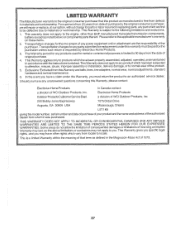
..., improper assembly or installation, delivery damage, or to any power equipment unit or attachment are belts, tines, tine adapters, normal wear, normal adjustments, standard hardware and normal maintenance. 6. Exclusions: Excluded from whom it was purchased. a division of WCI Outdoor Products, Inc. 250 Bobby Jones Expressway 7075 OrdanDrive Augusta, GA 30909 USA Mississauga, Ontario L5T 1K6 givingthe model number, serialnumber and...
..., improper assembly or installation, delivery damage, or to any power equipment unit or attachment are belts, tines, tine adapters, normal wear, normal adjustments, standard hardware and normal maintenance. 6. Exclusions: Excluded from whom it was purchased. a division of WCI Outdoor Products, Inc. 250 Bobby Jones Expressway 7075 OrdanDrive Augusta, GA 30909 USA Mississauga, Ontario L5T 1K6 givingthe model number, serialnumber and...


