

User Manual
Page 2
... on sidewalks, driveways and other reproductive harm. Use extension cords and receptacles as roofs of residences, garages, porches or other engine parts become extremely hot during operation or while performing an adjustment or repair to a running (except when specifically recommended by the manufacturer for...that can cause severe injury from contact, or from material thrown from the truck or trailer and refuel it cannot contact plug in moving parts. ing gravel drives, walks, or roads. ers on slippery surfaces. 4. Stay alert for this unit. Keep the area of operation...
... on sidewalks, driveways and other reproductive harm. Use extension cords and receptacles as roofs of residences, garages, porches or other engine parts become extremely hot during operation or while performing an adjustment or repair to a running (except when specifically recommended by the manufacturer for...that can cause severe injury from contact, or from material thrown from the truck or trailer and refuel it cannot contact plug in moving parts. ing gravel drives, walks, or roads. ers on slippery surfaces. 4. Stay alert for this unit. Keep the area of operation...

User Manual
Page 3
...PRODUCT SPECIFICATIONS 3 SERVICE AND ADJUSTMENTS 16-18 CUSTOMER RESPONSIBILITIES 3 STORAGE 18 ASSEMBLY / PRE-OPERATION 5-7 TROUBLESHOOTING 19 OPERATION 8-13 REPAIR PARTS 20-38 MAINTENANCE 14-15 3 WARRANTY 40 Never direct the discharge toward people or areas where property damage can occur. Never .... When cleaning, repairing or inspecting the snow thrower, stop the engine and make certain the collector/impeller and all moving parts have competent, well-trained technicians and the proper tools to operator's manual for transporting the snow thrower in safe working ....
...PRODUCT SPECIFICATIONS 3 SERVICE AND ADJUSTMENTS 16-18 CUSTOMER RESPONSIBILITIES 3 STORAGE 18 ASSEMBLY / PRE-OPERATION 5-7 TROUBLESHOOTING 19 OPERATION 8-13 REPAIR PARTS 20-38 MAINTENANCE 14-15 3 WARRANTY 40 Never direct the discharge toward people or areas where property damage can occur. Never .... When cleaning, repairing or inspecting the snow thrower, stop the engine and make certain the collector/impeller and all moving parts have competent, well-trained technicians and the proper tools to operator's manual for transporting the snow thrower in safe working ....

User Manual
Page 4
PARTS PACKED SEPARATELY IN CARTON (1) MULTIWRENCH (180684) (1) POWER CORD (198563) (1) SAFTEY IGNITION KEY (35062) (1) AUGER CONTROL ROD (1) TRACTION DRIVE CONTROL ROD (1) DISCHARGE CHUTE EXTRA SHEAR BOLTS ...
PARTS PACKED SEPARATELY IN CARTON (1) MULTIWRENCH (180684) (1) POWER CORD (198563) (1) SAFTEY IGNITION KEY (35062) (1) AUGER CONTROL ROD (1) TRACTION DRIVE CONTROL ROD (1) DISCHARGE CHUTE EXTRA SHEAR BOLTS ...

User Manual
Page 5
... securing the upper handle to the operating position and tighten handle knobs securely. Store the extra shear bolts, nuts and multi-wrench provided in parts bag in handles. Raise upper handle to the pallet. 6. Additional carriage bolts, washers and handle knobs are in bag of carton and lay... TO SET UP YOUR SNOW THROWER TOOL BOX (See Fig. 10) A toolbox is located on your snow thrower, all accessible loose parts and parts boxes from carton and check carton thoroughly for shipping purposes. Cut down all packing materials except plastic tie holding speed control rod to lower...
... securing the upper handle to the operating position and tighten handle knobs securely. Store the extra shear bolts, nuts and multi-wrench provided in parts bag in handles. Raise upper handle to the pallet. 6. Additional carriage bolts, washers and handle knobs are in bag of carton and lay... TO SET UP YOUR SNOW THROWER TOOL BOX (See Fig. 10) A toolbox is located on your snow thrower, all accessible loose parts and parts boxes from carton and check carton thoroughly for shipping purposes. Cut down all packing materials except plastic tie holding speed control rod to lower...
User Manual
Page 7
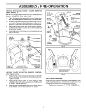
... important for shipping purposes. CHUTE DEFLECTOR CONTROL LEVER FIG. 9 CHECK TIRE PRESSURE The tires on top of snow thrower. 2. Place discharge chute assembly on your parts bag may be used to align square and pin on chute rotater head and into hole in your snow thrower were overinflated at the factory...
... important for shipping purposes. CHUTE DEFLECTOR CONTROL LEVER FIG. 9 CHECK TIRE PRESSURE The tires on top of snow thrower. 2. Place discharge chute assembly on your parts bag may be used to align square and pin on chute rotater head and into hole in your snow thrower were overinflated at the factory...

User Manual
Page 10
... on the engine. Slowly turn knob clockwise. If the discharge chute or auger become clogged, shut-off engine and wait for all moving parts to unclog the chute and/or auger. Be sure lever springs back and locks into desired position. OPERATION The operation of the chute deflector...choke, turn knob counterclockwise to stop . OFF FULL FIG. 13 TO CONTROL SNOW DISCHARGE (See Fig. 14) WARNING: Snow throwers have exposed rotating parts, which can cause severe injury from contact, or from material thrown from the discharge chute. Use the clean-out tool, NOT YOUR HANDS, to stop...
... on the engine. Slowly turn knob clockwise. If the discharge chute or auger become clogged, shut-off engine and wait for all moving parts to unclog the chute and/or auger. Be sure lever springs back and locks into desired position. OPERATION The operation of the chute deflector...choke, turn knob counterclockwise to stop . OFF FULL FIG. 13 TO CONTROL SNOW DISCHARGE (See Fig. 14) WARNING: Snow throwers have exposed rotating parts, which can cause severe injury from contact, or from material thrown from the discharge chute. Use the clean-out tool, NOT YOUR HANDS, to stop...

User Manual
Page 11
... you to turn in a safe direction (no vehicles, buildings, people, or other objects are disengaged and the auger/impeller and all moving parts have stopped. It is controlled by the auger control lever located on the underside of the snow thrower. TRACTION DRIVE CONTROL LEVER DRIVE SPEED ... is pointed in that direction. • To turn right - When cleaning, repairing, or inspecting, make certain all controls are in steering your parts bag may become clogged with the operation of each side of snow thrower and allows it 's mounting clip by the handle and push and twist...
... you to turn in a safe direction (no vehicles, buildings, people, or other objects are disengaged and the auger/impeller and all moving parts have stopped. It is controlled by the auger control lever located on the underside of the snow thrower. TRACTION DRIVE CONTROL LEVER DRIVE SPEED ... is pointed in that direction. • To turn right - When cleaning, repairing, or inspecting, make certain all controls are in steering your parts bag may become clogged with the operation of each side of snow thrower and allows it 's mounting clip by the handle and push and twist...

User Manual
Page 12
..., property damage or damage to the snow thrower. • If snow thrower must be picked up and thrown by loosening the hex nuts, then moving parts to bottom of 30 days or longer. BEFORE STARTING THE ENGINE CHECK ENGINE OIL LEVEL (See Fig. 21) The engine on level ground. 2. Remove oil...
..., property damage or damage to the snow thrower. • If snow thrower must be picked up and thrown by loosening the hex nuts, then moving parts to bottom of 30 days or longer. BEFORE STARTING THE ENGINE CHECK ENGINE OIL LEVEL (See Fig. 21) The engine on level ground. 2. Remove oil...

User Manual
Page 13
...the "OFF" position. WARNING: Do not use the electric starter. Push starter button until it clicks. Insert safety ignition key (packed separately in parts bag) into a three-hole grounded 120 Volt A.C. Place throttle control in a safe place. 2. Allow the engine to proper height for a few... whenever possible. • Adjust the skid plates to warm up for current snow conditions. Insert safety ignition key (packed separately in parts bag) into ignition slot until engine starts. Rotate choke control to operate on the engine. RECOIL STARTER Follow the steps above steps or...
...the "OFF" position. WARNING: Do not use the electric starter. Push starter button until it clicks. Insert safety ignition key (packed separately in parts bag) into a three-hole grounded 120 Volt A.C. Place throttle control in a safe place. 2. Allow the engine to proper height for a few... whenever possible. • Adjust the skid plates to warm up for current snow conditions. Insert safety ignition key (packed separately in parts bag) into ignition slot until engine starts. Rotate choke control to operate on the engine. RECOIL STARTER Follow the steps above steps or...

User Manual
Page 14
NOTE: Use only Original Equipment Manufacturer (OEM) parts to service this manual. Check for deterioration and wear after every 50 TIRES • Maintain proper air pressure in this manual. LUBRICATION CHART SAE 5W-...-24.5 N-m). Check V-belts for loose fasteners. 3. The V-belts on this manual). • Keep tires free of gasoline and oil, which can harm rubber. Using other parts dealer. Auger Engine oil SNOW THROWER grease fittings Always observe the safety rules when performing any V-BELTS maintenance. hours of this snow thrower does not...
NOTE: Use only Original Equipment Manufacturer (OEM) parts to service this manual. Check for deterioration and wear after every 50 TIRES • Maintain proper air pressure in this manual. LUBRICATION CHART SAE 5W-...-24.5 N-m). Check V-belts for loose fasteners. 3. The V-belts on this manual). • Keep tires free of gasoline and oil, which can harm rubber. Using other parts dealer. Auger Engine oil SNOW THROWER grease fittings Always observe the safety rules when performing any V-BELTS maintenance. hours of this snow thrower does not...
User Manual
Page 16
...foreign object or ice become lodged in the Operation section of the discharge chute, is engaged, check to STOP position. Disengage all moving parts to slip from the operator. The auger and traction drive belts are designed to break, preventing damage to see "TO CONTROL SNOW DISCHARGE...4. FRAME BELT COVER FIG. 23 SCREWS 2. If the belts are designed to break, preventing damage to stop . 2. Wait for all moving parts have sheared. Remove safety ignition key and disconnect spark plug TO REPLACE BELTS (See Fig. 24) wire from spark plug. IMPELLER SHEAR BOLTS ...
...foreign object or ice become lodged in the Operation section of the discharge chute, is engaged, check to STOP position. Disengage all moving parts to slip from the operator. The auger and traction drive belts are designed to break, preventing damage to see "TO CONTROL SNOW DISCHARGE...4. FRAME BELT COVER FIG. 23 SCREWS 2. If the belts are designed to break, preventing damage to stop . 2. Wait for all moving parts have sheared. Remove safety ignition key and disconnect spark plug TO REPLACE BELTS (See Fig. 24) wire from spark plug. IMPELLER SHEAR BOLTS ...

User Manual
Page 17
... in pulley groove when bringing the snow thrower together. 14. Install flat washer, lockwasher and bolt and tighten securely (41-47 N-m torque). With your local parts belt around pulleys. INSTALL ENGINE PULLEY - Wipe up on idler, install new traction drive leaks, tire sealant may be sure to the end of auger...
... in pulley groove when bringing the snow thrower together. 14. Install flat washer, lockwasher and bolt and tighten securely (41-47 N-m torque). With your local parts belt around pulleys. INSTALL ENGINE PULLEY - Wipe up on idler, install new traction drive leaks, tire sealant may be sure to the end of auger...

User Manual
Page 18
.... store it thoroughly, remove all dirt, grease, leaves, etc. Do not use engine or carburetor cleaner products in essential fuel system parts such as on stabilizer container. SERVICE AND ADJUSTMENTS KLIK PIN (INSTALL IN OUTER HOLE OF AXLE ONLY) WHEEL ENGINE See engine manual....of this manual). 3. WARNING: Never store the snow thrower with clean engine oil. (See "ENGINE" in fuel tank or storage container. Inspect moving parts for storage at altitudes up all nuts, bolts, screws, and pins are empty. • Never use plastic. Replace if necessary. 5. Add stabilizer...
.... store it thoroughly, remove all dirt, grease, leaves, etc. Do not use engine or carburetor cleaner products in essential fuel system parts such as on stabilizer container. SERVICE AND ADJUSTMENTS KLIK PIN (INSTALL IN OUTER HOLE OF AXLE ONLY) WHEEL ENGINE See engine manual....of this manual). 3. WARNING: Never store the snow thrower with clean engine oil. (See "ENGINE" in fuel tank or storage container. Inspect moving parts for storage at altitudes up all nuts, bolts, screws, and pins are empty. • Never use plastic. Replace if necessary. 5. Add stabilizer...

User Manual
Page 19
... a few minutes before restarting, DO NOT prime. 8. Drain fuel tank and carburetor, refill tank with fresh gasoline. Water in STOP position. 5. Loose parts or damaged augers or impeller. 1. Replace damaged parts. drive / slowing 2. Friction drive wheel is worn. 1. Auger belt is not inserted. 3. Clogged discharge chute. 4. Safety ignition key is worn. 3. Primer...
... a few minutes before restarting, DO NOT prime. 8. Drain fuel tank and carburetor, refill tank with fresh gasoline. Water in STOP position. 5. Loose parts or damaged augers or impeller. 1. Replace damaged parts. drive / slowing 2. Friction drive wheel is worn. 1. Auger belt is not inserted. 3. Clogged discharge chute. 4. Safety ignition key is worn. 3. Primer...

User Manual
Page 21
Failure to do so could be hazardous, damage your snow thrower and void your warranty. 21 REPAIR PARTS SNOW THROWER - MODEL PP11530ES (96192001902) AUGER HOUSING / IMPELLER ASSEMBLY KEY NO. 1 2 3 4 5 6 7 8 9 10 11 12 13 14 15 16 17... 18 19 20 21 22 23 24 25 26 27 28 29 30 31 32 33 34 35 36 PART NO. 175321X479 196710 ...: All component dimensions given in U.S. inches. 1 inch = 25.4 mm IMPORTANT: Use only Original Equipment Manufacturer (O.E.M.) replacement parts.
Failure to do so could be hazardous, damage your snow thrower and void your warranty. 21 REPAIR PARTS SNOW THROWER - MODEL PP11530ES (96192001902) AUGER HOUSING / IMPELLER ASSEMBLY KEY NO. 1 2 3 4 5 6 7 8 9 10 11 12 13 14 15 16 17... 18 19 20 21 22 23 24 25 26 27 28 29 30 31 32 33 34 35 36 PART NO. 175321X479 196710 ...: All component dimensions given in U.S. inches. 1 inch = 25.4 mm IMPORTANT: Use only Original Equipment Manufacturer (O.E.M.) replacement parts.

User Manual
Page 22
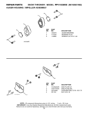
... to do so could be hazardous, damage your snow thrower and void your warranty. 22 REPAIR PARTS SNOW THROWER - MODEL PP11530ES (96192001902) AUGER HOUSING / IMPELLER ASSEMBLY 1 3 (5x) 4 (5x) 2 01.07.003-A KEY NO. 1 2 3 4 PART NO. 404930X428 404933X479 72270505 155377 DESCRIPTION AUGER HOUSING SCRAPPER BAR CARRIAGE BOLT 5/16−18 X .625 NUT 5/16−...
... to do so could be hazardous, damage your snow thrower and void your warranty. 22 REPAIR PARTS SNOW THROWER - MODEL PP11530ES (96192001902) AUGER HOUSING / IMPELLER ASSEMBLY 1 3 (5x) 4 (5x) 2 01.07.003-A KEY NO. 1 2 3 4 PART NO. 404930X428 404933X479 72270505 155377 DESCRIPTION AUGER HOUSING SCRAPPER BAR CARRIAGE BOLT 5/16−18 X .625 NUT 5/16−...
User Manual
Page 23
... your snow thrower and void your warranty. 23 REPAIR PARTS SNOW THROWER - MODEL PP11530ES (96192001902) AUGER HOUSING / IMPELLER ASSEMBLY 2 3 1 1 2 3 01.07.024-B KEY NO. 1 2 3 PART NO. 420478 411939 179582 DESCRIPTION AUGER BEARING BEARING PLUG SCREW 5/16−18 X 1.00 3 4 3 01.11.001-A 1 4 2 KEY NO. 1 2 3 4 PART NO. 174762X479 178777X479 72270506 751153 DESCRIPTION SKID PLATE LH...
... your snow thrower and void your warranty. 23 REPAIR PARTS SNOW THROWER - MODEL PP11530ES (96192001902) AUGER HOUSING / IMPELLER ASSEMBLY 2 3 1 1 2 3 01.07.024-B KEY NO. 1 2 3 PART NO. 420478 411939 179582 DESCRIPTION AUGER BEARING BEARING PLUG SCREW 5/16−18 X 1.00 3 4 3 01.11.001-A 1 4 2 KEY NO. 1 2 3 4 PART NO. 174762X479 178777X479 72270506 751153 DESCRIPTION SKID PLATE LH...

User Manual
Page 24
...3 179246 PLASTIC WASHER 1 4 3 5 4 4 10040500 LOCKWASHER 5/16 5 128638 NUT 5/16−18 4 3 2 01.16.001-A 1 2 2 KEY PART NO. DESCRIPTION 1 182516 WEIGHT BAR 2 72110510 CARRIAGE BOLT 5/16−18 X 1.25 3 3 751153 NUT 5/16−18 01.17.003-A 3 NOTE: ...All component dimensions given in U.S. MODEL PP11530ES (96192001902) AUGER HOUSING / IMPELLER ASSEMBLY 1 3 2 KEY PART 4 NO. REPAIR PARTS SNOW THROWER - NO. inches. 1 inch = 25.4 mm IMPORTANT: Use only Original Equipment Manufacturer (O.E.M.) replacement parts. Failure to do so could be hazardous...
...3 179246 PLASTIC WASHER 1 4 3 5 4 4 10040500 LOCKWASHER 5/16 5 128638 NUT 5/16−18 4 3 2 01.16.001-A 1 2 2 KEY PART NO. DESCRIPTION 1 182516 WEIGHT BAR 2 72110510 CARRIAGE BOLT 5/16−18 X 1.25 3 3 751153 NUT 5/16−18 01.17.003-A 3 NOTE: ...All component dimensions given in U.S. MODEL PP11530ES (96192001902) AUGER HOUSING / IMPELLER ASSEMBLY 1 3 2 KEY PART 4 NO. REPAIR PARTS SNOW THROWER - NO. inches. 1 inch = 25.4 mm IMPORTANT: Use only Original Equipment Manufacturer (O.E.M.) replacement parts. Failure to do so could be hazardous...

User Manual
Page 25
...U.S. inches. 1 inch = 25.4 mm IMPORTANT: Use only Original Equipment Manufacturer (O.E.M.) replacement parts. MODEL PP11530ES (96192001902) CONTROL PANEL / DISCHARGE CHUTE 5 7 14 3 15 *13 KEY NO. 1 2 3 4 5 6 7 *8 *9 *10 *11 *12 *13 14 15 PART NO. 404770X428 178633X428 420673 420325 414280 128415 17501010 179829 179246 191730 72250505 751153 184505 420679 420672 ...PLASTIC WASHER NUT 1/4−20 CARRIAGE BOLT 5/16−18 X .50 NUT 5/16−18 DEFLECTOR SPRING (SERVICE PART) DEFLECTOR CONTROL HEAD (SERVICE PART) DEFLECTOR CONTROL CABLE *10 *9 *8 6 *12 *11 01.09.002-B NOTE: 1.
...U.S. inches. 1 inch = 25.4 mm IMPORTANT: Use only Original Equipment Manufacturer (O.E.M.) replacement parts. MODEL PP11530ES (96192001902) CONTROL PANEL / DISCHARGE CHUTE 5 7 14 3 15 *13 KEY NO. 1 2 3 4 5 6 7 *8 *9 *10 *11 *12 *13 14 15 PART NO. 404770X428 178633X428 420673 420325 414280 128415 17501010 179829 179246 191730 72250505 751153 184505 420679 420672 ...PLASTIC WASHER NUT 1/4−20 CARRIAGE BOLT 5/16−18 X .50 NUT 5/16−18 DEFLECTOR SPRING (SERVICE PART) DEFLECTOR CONTROL HEAD (SERVICE PART) DEFLECTOR CONTROL CABLE *10 *9 *8 6 *12 *11 01.09.002-B NOTE: 1.

User Manual
Page 26
... void your warranty. 26 ITEMS INDICATED WITH AN * ARE LISTED AS REFERENCE FOR SERVICE PARTS ONLY. 2 1 KEY PART NO. inches. 1 inch = 25.4 mm IMPORTANT: Use only Original Equipment Manufacturer (O.E.M.) replacement parts. MODEL PP11530ES (96192001902) CONTROL PANEL / DISCHARGE CHUTE 2 2 *3 1 *6 KEY NO. 1 2 *3 *4 *5 *6 PART NO. 420337 17501010 420678 420677 420675 420674 *6 DESCRIPTION LEVER/CABLE ROTATOR ASSEMBLY SCREW 10...
... void your warranty. 26 ITEMS INDICATED WITH AN * ARE LISTED AS REFERENCE FOR SERVICE PARTS ONLY. 2 1 KEY PART NO. inches. 1 inch = 25.4 mm IMPORTANT: Use only Original Equipment Manufacturer (O.E.M.) replacement parts. MODEL PP11530ES (96192001902) CONTROL PANEL / DISCHARGE CHUTE 2 2 *3 1 *6 KEY NO. 1 2 *3 *4 *5 *6 PART NO. 420337 17501010 420678 420677 420675 420674 *6 DESCRIPTION LEVER/CABLE ROTATOR ASSEMBLY SCREW 10...


