

Uk Manual
Page 3
.... Do not operate the treadmill if the power cord or plug is damaged, or if the treadmill is capable of heart rate readings. Never allow more than 5 ft. (1.5 m). 4. The treadmill is not working properly.) 15. The pulse sensor is turned off. ICON assumes no longer than one person on each side. When connecting the power cord (see HOW TO TURN ON THE POWER on the walking belt. To protect the...
.... Do not operate the treadmill if the power cord or plug is damaged, or if the treadmill is capable of heart rate readings. Never allow more than 5 ft. (1.5 m). 4. The treadmill is not working properly.) 15. The pulse sensor is turned off. ICON assumes no longer than one person on each side. When connecting the power cord (see HOW TO TURN ON THE POWER on the walking belt. To protect the...

Uk Manual
Page 4
... in this treadmill in the storage position. 22. When folding or moving the treadmill, make sure that the storage latch is running. Do not use , before cleaning the treadmill, and before performing the mainte- Over exercising may result in this manual. vice representative. Never leave the treadmill unattended while it is not in -home use only. Always remove the key, unplug the power cord, and press the power switch into any...
... in this treadmill in the storage position. 22. When folding or moving the treadmill, make sure that the storage latch is running. Do not use , before cleaning the treadmill, and before performing the mainte- Over exercising may result in this manual. vice representative. Never leave the treadmill unattended while it is not in -home use only. Always remove the key, unplug the power cord, and press the power switch into any...
Uk Manual
Page 5
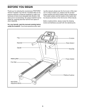
If you ʼre not exercising, the unique treadmill can be folded up, requiring less than half the floor space of this manual carefully before contacting us assist you for selecting the revolutionary PROFORM® 700 ZLT treadmill. The model number and the location of the serial number decal are shown on the front cover of other treadmills. Tray Handrail Upright Walking Belt Foot Rail Console Pulse Sensor Key/Clip Power Switch Idler Roller Adjustment Bolts Platform Cushion 5 And when...
If you ʼre not exercising, the unique treadmill can be folded up, requiring less than half the floor space of this manual carefully before contacting us assist you for selecting the revolutionary PROFORM® 700 ZLT treadmill. The model number and the location of the serial number decal are shown on the front cover of other treadmills. Tray Handrail Upright Walking Belt Foot Rail Console Pulse Sensor Key/Clip Power Switch Idler Roller Adjustment Bolts Platform Cushion 5 And when...
Uk Manual
Page 10
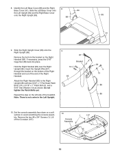
... Upright (85). Attach the Right Handrail (83) to avoid scratching the console assembly. Slide the Left Base Cover onto 84 the Left Upright (84) and the Right Base Cover onto the Right Upright (85). 88 85 91 9. Set the console assembly face down on the Right Handrail (83). Do not tighten the Patch Bolts yet. Lift off the Crossbar (107). 10 Console Assembly 1 107 10 Remove...
... Upright (85). Attach the Right Handrail (83) to avoid scratching the console assembly. Slide the Left Base Cover onto 84 the Left Upright (84) and the Right Base Cover onto the Right Upright (85). 88 85 91 9. Set the console assembly face down on the Right Handrail (83). Do not tighten the Patch Bolts yet. Lift off the Crossbar (107). 10 Console Assembly 1 107 10 Remove...

Uk Manual
Page 11
... CONNECT THE CONNECTORS PROPERLY, THE CONSOLE MAY BECOME DAMAGED WHEN YOU TURN ON THE POWER. Attach the Console Frame with four #10 12 x 3/4" Screws (2) and four #10 Star Washers (12); First 29 12 87 Tighten one #10 x 3/4" Screw (2) in each end 83 of a second person, hold the console assembly near the Right Handrail (83) and the Left Handrail (not shown). Connect the Upright Wire...
... CONNECT THE CONNECTORS PROPERLY, THE CONSOLE MAY BECOME DAMAGED WHEN YOU TURN ON THE POWER. Attach the Console Frame with four #10 12 x 3/4" Screws (2) and four #10 Star Washers (12); First 29 12 87 Tighten one #10 x 3/4" Screw (2) in each end 83 of a second person, hold the console assembly near the Right Handrail (83) and the Left Handrail (not shown). Connect the Upright Wire...
Uk Manual
Page 12
... the console assembly. Attach the Left Upright Cover (80) to the Crossbar (107) with six #8 x 3/4" Screws (1). See steps 5 and 7. Set the console assembly on page 21). 15 55 10 8 Latch Knob 51 Large Barrel 6 95 10 8 12 Start all six Screws, and then tighten each of the Storage Latch (51) to the console assembly with two #8 x 3/4" Screws (1). Align the holes in the Right 14 Upright Cover with the bracket. Attach the Latch Bracket (6) and Storage Latch...
... the console assembly. Attach the Left Upright Cover (80) to the Crossbar (107) with six #8 x 3/4" Screws (1). See steps 5 and 7. Set the console assembly on page 21). 15 55 10 8 Latch Knob 51 Large Barrel 6 95 10 8 12 Start all six Screws, and then tighten each of the Storage Latch (51) to the console assembly with two #8 x 3/4" Screws (1). Align the holes in the Right 14 Upright Cover with the bracket. Attach the Latch Bracket (6) and Storage Latch...

Uk Manual
Page 13
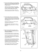
... #8 x 3/4" Screws (1) and the 1 four #8 x 1/2" Screws (16) from the back of console assembly. Locate the Short Wire (B) on the back of the Console Base (106). 1 16 1 106 16 2. Discard the other wires included with the chest pulse sensor. 1. Make sure that the power cord is oriented as shown. If there are sheets of the hex keys is used to adjust the walking belt (see page 20), follow the steps below...
... #8 x 3/4" Screws (1) and the 1 four #8 x 1/2" Screws (16) from the back of console assembly. Locate the Short Wire (B) on the back of the Console Base (106). 1 16 1 106 16 2. Discard the other wires included with the chest pulse sensor. 1. Make sure that the power cord is oriented as shown. If there are sheets of the hex keys is used to adjust the walking belt (see page 20), follow the steps below...
Uk Manual
Page 14
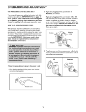
... POWER CORD This product must be earthed. This product is properly earthed. Do not modify the plug provided with a qualified electrician or serviceman if you are in doubt as shown. Then, go to step 3. Screw Adapter Cover Pins Adapter Metal Clips 3. UK Outlet Australia Outlet 1. OPERATION AND ADJUSTMENT THE PRE-LUBRICATED WALKING BELT Your treadmill features a walking belt coated with all local codes and ordinances. DANGER: Improper connection...
... POWER CORD This product must be earthed. This product is properly earthed. Do not modify the plug provided with a qualified electrician or serviceman if you are in doubt as shown. Then, go to step 3. Screw Adapter Cover Pins Adapter Metal Clips 3. UK Outlet Australia Outlet 1. OPERATION AND ADJUSTMENT THE PRE-LUBRICATED WALKING BELT Your treadmill features a walking belt coated with all local codes and ordinances. DANGER: Improper connection...

Uk Manual
Page 15
... iFit cards with the touch of the treadmill as it guides you can listen to make your heart rate using the handgrip pulse sensor or the optional chest pulse sensor (see page 20 for information on the power, see page 16. To use a quick calorie burn workout, see page 20. outs that help you exercise, the console will display continuous exercise feedback. iFit cards are available separately. Each workout automatically controls the speed and incline of a button...
... iFit cards with the touch of the treadmill as it guides you can listen to make your heart rate using the handgrip pulse sensor or the optional chest pulse sensor (see page 20 for information on the power, see page 16. To use a quick calorie burn workout, see page 20. outs that help you exercise, the console will display continuous exercise feedback. iFit cards are available separately. Each workout automatically controls the speed and incline of a button...
Uk Manual
Page 16
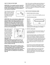
... MANUAL MODE 1. See HOW TO TURN ON THE POWER at 2 Km/H. To turn off the demo mode, hold down the Stop button for a few steps back- If Track you hold down the button, the speed setting will begin to kilometers. Find the clip attached Key to room temperature before turning on the power. Clip plays will be used if the treadmill is displayed in the power cord and press the power switch into the reset position, the demo mode...
... MANUAL MODE 1. See HOW TO TURN ON THE POWER at 2 Km/H. To turn off the demo mode, hold down the Stop button for a few steps back- If Track you hold down the button, the speed setting will begin to kilometers. Find the clip attached Key to room temperature before turning on the power. Clip plays will be used if the treadmill is displayed in the power cord and press the power switch into the reset position, the demo mode...

Uk Manual
Page 17
... optional chest pulse sensor. Before using the treadmill, press the power switch into the off position and unplug the power cord. avoid moving your progress with the displays. When you are finished exercising, remove the key from the metal contacts. When you have burned, the speed of the walking belt, and your heart beats, one of the treadmill. When the manual mode is selected, the display will gradually adjust to the lowest setting. The track will...
... optional chest pulse sensor. Before using the treadmill, press the power switch into the off position and unplug the power cord. avoid moving your progress with the displays. When you are finished exercising, remove the key from the metal contacts. When you have burned, the speed of the walking belt, and your heart beats, one of the treadmill. When the manual mode is selected, the display will gradually adjust to the lowest setting. The track will...

Uk Manual
Page 18
... - Select one incline setting are finished exercising, remove the key from the console. To restart the workout, press the Go button or the Speed increase button. At the end of the workout. See HOW TO TURN ON THE POWER on page 17. Press the Go button or the Speed increase button to move at any time, press the Stop button. A moment after you . Hold the handrails and begin to start the workout. See step 6 on...
... - Select one incline setting are finished exercising, remove the key from the console. To restart the workout, press the Go button or the Speed increase button. At the end of the workout. See HOW TO TURN ON THE POWER on page 17. Press the Go button or the Speed increase button to move at any time, press the Stop button. A moment after you . Hold the handrails and begin to start the workout. See step 6 on...

Uk Manual
Page 19
... adjust to the speed and incline settings for your personal trainer (see THE INFORMATION MODE on the front cover of the workout will appear in the display for the next segment. If the profile does not appear, press the Display button repeatedly. 4. See step 6 on page 17. Each iFit workout is properly inserted, the iFit logo will guide you are programmed for each segment. One speed setting and one incline setting are not using...
... adjust to the speed and incline settings for your personal trainer (see THE INFORMATION MODE on the front cover of the workout will appear in the display for the next segment. If the profile does not appear, press the Display button repeatedly. 4. See step 6 on page 17. Each iFit workout is properly inserted, the iFit logo will guide you are programmed for each segment. One speed setting and one incline setting are not using...

Uk Manual
Page 20
... buttons will show the number of hours that the treadmill has been operated. To use an iFit card, a personal trainer will appear in the power cord, press the power switch into the reset position, and insert the key into a jack on , a "d" will appear in the display. THE OPTIONAL CHEST PULSE SENSOR An optional chest pulse sensor offers hands-free operation as it into the console, and then release the Stop button. You can select an audio setting...
... buttons will show the number of hours that the treadmill has been operated. To use an iFit card, a personal trainer will appear in the power cord, press the power switch into the reset position, and insert the key into a jack on , a "d" will appear in the display. THE OPTIONAL CHEST PULSE SENSOR An optional chest pulse sensor offers hands-free operation as it into the console, and then release the Stop button. You can select an audio setting...

Uk Manual
Page 21
...Make sure that the latch knob is locked in the storage position. if necessary, push the frame forward slightly. Then, remove the key and unplug the power cord. CAUTION: Do not hold the frame by the plastic foot rails, and do not move the treadmill without tipping it ...carefully lower the treadmill. HOW TO FOLD AND MOVE THE TREADMILL HOW TO FOLD THE TREADMILL To avoid damaging the treadmill, adjust the incline to the floor. Hold the frame and one foot against a wheel. 1 1 Frame Frame Handrail Wheel 2. Do not leave the treadmill in the storage position in the location shown...
...Make sure that the latch knob is locked in the storage position. if necessary, push the frame forward slightly. Then, remove the key and unplug the power cord. CAUTION: Do not hold the frame by the plastic foot rails, and do not move the treadmill without tipping it ...carefully lower the treadmill. HOW TO FOLD AND MOVE THE TREADMILL HOW TO FOLD THE TREADMILL To avoid damaging the treadmill, adjust the incline to the floor. Hold the frame and one foot against a wheel. 1 1 Frame Frame Handrail Wheel 2. Do not leave the treadmill in the storage position in the location shown...

Uk Manual
Page 22
... turn off the demo mode, hold down the Uprights (84, 85). b. Check the power switch located on page 20 to be solved by following the simple steps below. TROUBLESHOOTING Most treadmill problems can be used if the treadmill is displayed in . (13 cm) long is plugged into a properly earthed outlet (see the drawing above). c. PROBLEM: The console displays remain lit when you remove the key, the demo mode is inserted into the console...
... turn off the demo mode, hold down the Uprights (84, 85). b. Check the power switch located on page 20 to be solved by following the simple steps below. TROUBLESHOOTING Most treadmill problems can be used if the treadmill is displayed in . (13 cm) long is plugged into a properly earthed outlet (see the drawing above). c. PROBLEM: The console displays remain lit when you remove the key, the demo mode is inserted into the console...

Uk Manual
Page 23
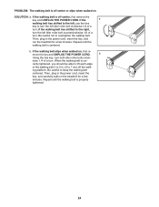
... walking belt still slows when walked on SOLUTION: a. If an extension cord is needed, use only a 3-conductor, 14-gauge (1 mm2) cord that the gap between the Magnet and 1/8 in . The treadmill will recalibrate the incline system. With the key in . (3 mm). Reattach the Motor Hood (not shown) 48 with the Reed Switch. Idler Roller Bolts c. Make sure that is about 1/8 in the console, press one of this manual. 23 Remove...
... walking belt still slows when walked on SOLUTION: a. If an extension cord is needed, use only a 3-conductor, 14-gauge (1 mm2) cord that the gap between the Magnet and 1/8 in . The treadmill will recalibrate the incline system. With the key in . (3 mm). Reattach the Motor Hood (not shown) 48 with the Reed Switch. Idler Roller Bolts c. Make sure that is about 1/8 in the console, press one of this manual. 23 Remove...
Uk Manual
Page 24
... idler roller bolt counterclockwise 1/2 of a turn ; Then, plug in the power cord, insert the key, and run the treadmill for a few minutes. move the key and UNPLUG THE POWER CORD. rectly tightened, you should be able to 7 cm) off -center or slips when walked on SOLUTION: a. wise, 1/4 of a turn both idler roller bolts clock- Then, plug in . (5 to lift each edge of a turn . b Using the hex key, turn . If the walking belt slips when walked on the treadmill...
... idler roller bolt counterclockwise 1/2 of a turn ; Then, plug in the power cord, insert the key, and run the treadmill for a few minutes. move the key and UNPLUG THE POWER CORD. rectly tightened, you should be able to 7 cm) off -center or slips when walked on SOLUTION: a. wise, 1/4 of a turn both idler roller bolts clock- Then, plug in . (5 to lift each edge of a turn . b Using the hex key, turn . If the walking belt slips when walked on the treadmill...

Uk Manual
Page 25
... few minutes of exercise, your exercise program. The chart below shows recommended heart rates for aerobic exercise. The three numbers listed above your age define your training zone. For aerobic exercise, adjust the intensity of regular exercise, you exercise-never hold your body begin to 30 minutes with pre-existing health problems. The pulse sensor is to burn fat or to make exercise a regular and enjoyable part of the chart (ages are...
... few minutes of exercise, your exercise program. The chart below shows recommended heart rates for aerobic exercise. The three numbers listed above your age define your training zone. For aerobic exercise, adjust the intensity of regular exercise, you exercise-never hold your body begin to 30 minutes with pre-existing health problems. The pulse sensor is to burn fat or to make exercise a regular and enjoyable part of the chart (ages are...
Uk Manual
Page 26
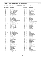
... Storage Latch Console Ground Wire #8 x 1" Screw Right Foot Rail Frame Roller Bracket Roller Ground Wire Right Rear Foot Left Rear Foot Idler Roller Hex Key Motor Hood Hood Accent Lift Frame Lift Frame Ground Wire Drive Motor Belt Drive Motor Controller Ground Wire Power Cord Receptacle Power Switch Controller Reed Switch Reed Switch Clamp Belly Pan Wire Tie 8" Tie 15" Tie Releasable Tie Left Upright Cover Handrail Cap Left Handrail Right Handrail Left Upright Right Upright Right Upright Cover Upright Wire Left Base Cover Base Cap Base Foot Right Base Cover Caution Decal Incline Wire...
... Storage Latch Console Ground Wire #8 x 1" Screw Right Foot Rail Frame Roller Bracket Roller Ground Wire Right Rear Foot Left Rear Foot Idler Roller Hex Key Motor Hood Hood Accent Lift Frame Lift Frame Ground Wire Drive Motor Belt Drive Motor Controller Ground Wire Power Cord Receptacle Power Switch Controller Reed Switch Reed Switch Clamp Belly Pan Wire Tie 8" Tie 15" Tie Releasable Tie Left Upright Cover Handrail Cap Left Handrail Right Handrail Left Upright Right Upright Right Upright Cover Upright Wire Left Base Cover Base Cap Base Foot Right Base Cover Caution Decal Incline Wire...


