
User Manual
Page 1
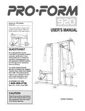
... and instructions in this manual before using this manual for future reference. ¨ USERÕS MANUAL PATENT PENDING The trained technicians on our customer hot line will guarantee complete satisfaction through direct assistance from our factory. The serial number is found in the space above. As a manufacturer, we are committed to you have questions, or if there are missing or damaged parts...
... and instructions in this manual before using this manual for future reference. ¨ USERÕS MANUAL PATENT PENDING The trained technicians on our customer hot line will guarantee complete satisfaction through direct assistance from our factory. The serial number is found in the space above. As a manufacturer, we are committed to you have questions, or if there are missing or damaged parts...

User Manual
Page 2
... the press arm, butterfly arms, leg lever, lat bar, row bar or ankle strap while weights are on the pulleys at any time while exercising, stop immediately and make sure the cables are raised. Always disconnect the lat bar, row bar or ankle strap from the home gym system at a time. 3. Table of Contents Important Precautions 2 Before You Begin 3 Assembly 4 Cable Diagram 19 Adjustment 20 Weight Resistance Chart 22 Trouble-shooting and Maintenance 23 Ordering Replacement Parts Back Cover Limited Warranty Back Cover Note: A PART LIST...
... the press arm, butterfly arms, leg lever, lat bar, row bar or ankle strap while weights are on the pulleys at any time while exercising, stop immediately and make sure the cables are raised. Always disconnect the lat bar, row bar or ankle strap from the home gym system at a time. 3. Table of Contents Important Precautions 2 Before You Begin 3 Assembly 4 Cable Diagram 19 Adjustment 20 Weight Resistance Chart 22 Trouble-shooting and Maintenance 23 Ordering Replacement Parts Back Cover Limited Warranty Back Cover Note: A PART LIST...
User Manual
Page 3
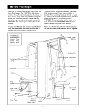
... Arms Backrest Seat Leg Lever Low Pulley Station Foot Plate Shroud Covering Weight Stack 3 Locking Pin Press Arm Backrest Seat Adjustment Knob Width: 38 in . Customer Service Department toll-free at 1-800-9993756, Monday through Friday, 6 a.m. The model number is to achieve the results you have additional questions, please call our Please use the drawing below to the PROFORM¨ 920 Home Gym System (see the front cover of the body. The serial number...
... Arms Backrest Seat Leg Lever Low Pulley Station Foot Plate Shroud Covering Weight Stack 3 Locking Pin Press Arm Backrest Seat Adjustment Knob Width: 38 in . Customer Service Department toll-free at 1-800-9993756, Monday through Friday, 6 a.m. The model number is to achieve the results you have additional questions, please call our Please use the drawing below to the PROFORM¨ 920 Home Gym System (see the front cover of the body. The serial number...

User Manual
Page 4
... process over a couple of this manual. Place the chart on the floor or work table and use it has been pre-attached. If a part is large enough to quickly identify different parts as the skeleton of the Assembly Process Frame Assembly You will begin each other and with many small parts. Cable Assembly Completes the cables and pulleys that assembly stage. The Four Stages of...
... process over a couple of this manual. Place the chart on the floor or work table and use it has been pre-attached. If a part is large enough to quickly identify different parts as the skeleton of the Assembly Process Frame Assembly You will begin each other and with many small parts. Cable Assembly Completes the cables and pulleys that assembly stage. The Four Stages of...
User Manual
Page 7
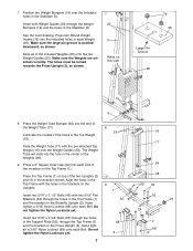
... Frame (1). Insert two 5/16Ó x 2 1/2Ó Bolts (45) with the pre-attached Top Weight (16) onto the Weight Guides (23). The holes must be turned towards the Press Upright (3), as shown. Lubricate the insides of the included Weights (26) onto the two Weight Guides (23). Hand tighten a 5/16Ó Nylon Locknut (68) unto each Bolt. Do not tighten the Nylon Locknuts yet. 68 3 7 16 77...
... Frame (1). Insert two 5/16Ó x 2 1/2Ó Bolts (45) with the pre-attached Top Weight (16) onto the Weight Guides (23). The holes must be turned towards the Press Upright (3), as shown. Lubricate the insides of the included Weights (26) onto the two Weight Guides (23). Hand tighten a 5/16Ó Nylon Locknut (68) unto each Bolt. Do not tighten the Nylon Locknuts yet. 68 3 7 16 77...

User Manual
Page 8
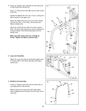
... it must be a tight fit. Tighten all three parts. Press Arm AssemblyÑLocate and open the parts 13 bag labeled ÒARM ASSEMBLY.Ó 24 59 Lubricate Press a 2Ó Square Inner Cap (24) into the Butterfly Seat Frame (11). Slide the Cable Frame (57) in steps 6 through 12. 11 24 60 2 68 8 Arm Assembly 22 13. Slide both the Cable Frame and the Press Frame onto the Top Frame...
... it must be a tight fit. Tighten all three parts. Press Arm AssemblyÑLocate and open the parts 13 bag labeled ÒARM ASSEMBLY.Ó 24 59 Lubricate Press a 2Ó Square Inner Cap (24) into the Butterfly Seat Frame (11). Slide the Cable Frame (57) in steps 6 through 12. 11 24 60 2 68 8 Arm Assembly 22 13. Slide both the Cable Frame and the Press Frame onto the Top Frame...
User Manual
Page 9
It has a Locking Pin (98) mounted on the Seat facing away from the weight stack. 46 Make sure both ends of each Butterfly Arm (80 and 81). Attach the Left Press Arm (46) in reference to the Press Frame 50 (12) with two 3/8Ó x 2 3/4Ó Bolts (18) and two 3/8Ó Nylon Locknuts (50). Leg Lever Assembly 15 Attach the Leg Lever (29) to the...
It has a Locking Pin (98) mounted on the Seat facing away from the weight stack. 46 Make sure both ends of each Butterfly Arm (80 and 81). Attach the Left Press Arm (46) in reference to the Press Frame 50 (12) with two 3/8Ó x 2 3/4Ó Bolts (18) and two 3/8Ó Nylon Locknuts (50). Leg Lever Assembly 15 Attach the Leg Lever (29) to the...
User Manual
Page 10
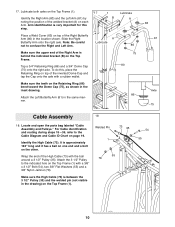
... Frame. 17. Note: Be careful not to the indicated hole on page 19. Locate and open the parts bag labeled ÒCable Assembly and Pulleys.Ó For Cable identification and routing during steps 18Ñ36, refer to the Cable Diagram and Cable ID Chart on the Top Frame (1) with the ball around a 3 1/2Ó Pulley (35). Attach the 3 1/2Ó Pulley to confuse the Right and Left Arm.
... Frame. 17. Note: Be careful not to the indicated hole on page 19. Locate and open the parts bag labeled ÒCable Assembly and Pulleys.Ó For Cable identification and routing during steps 18Ñ36, refer to the Cable Diagram and Cable ID Chart on the Top Frame (1) with the ball around a 3 1/2Ó Pulley (35). Attach the 3 1/2Ó Pulley to confuse the Right and Left Arm.
User Manual
Page 11
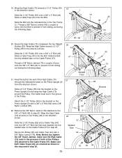
... a Cable Trap (44) onto the Bolt. Note: Before you tighten the 3/8Ó Nylon Jamnut, make sure the High Cable (73) rests in the grooves of the Pulleys (35) attached to the 3/8Ó x 5Ó Bolt (42) in the direction shown. Slide a 3 1/2Ó Pulley (35) into the welded tube on the Press Upright (3) and wrap the High Cable (73) around a 3 1/2Ó Pulley (35) in step 20...
... a Cable Trap (44) onto the Bolt. Note: Before you tighten the 3/8Ó Nylon Jamnut, make sure the High Cable (73) rests in the grooves of the Pulleys (35) attached to the 3/8Ó x 5Ó Bolt (42) in the direction shown. Slide a 3 1/2Ó Pulley (35) into the welded tube on the Press Upright (3) and wrap the High Cable (73) around a 3 1/2Ó Pulley (35) in step 20...
User Manual
Page 12
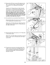
... one of the removed 3 1/2Ó Pulleys (35) in step 19. Attach the 3 1/2Ó Pulley (35) to the 3/8Ó x 5Ó Bolt (42) in the direction shown. Dis-assemble the pre-assembled Pulley Plates (31). It will be permanently attached in the direction shown. Wrap the High Cable (73) around a 3 1/2Ó Pulley (35) 25 1 62 in step 19. Secure the Pulley and Cable Trap with a 3/8Ó x 2Ó Bolt (62) and...
... one of the removed 3 1/2Ó Pulleys (35) in step 19. Attach the 3 1/2Ó Pulley (35) to the 3/8Ó x 5Ó Bolt (42) in the direction shown. Dis-assemble the pre-assembled Pulley Plates (31). It will be permanently attached in the direction shown. Wrap the High Cable (73) around a 3 1/2Ó Pulley (35) 25 1 62 in step 19. Secure the Pulley and Cable Trap with a 3/8Ó x 2Ó Bolt (62) and...

User Manual
Page 13
... Dis-assemble the second set of Pulley Plates (31). 2 28 Wrap the Butterfly Cable (97) around one of the Butterfly Cable (97) to side. Attach the 3 1/2Ó Pulley (35) and a Cable Trap (44) to the indicated bracket on the Left Butterfly Arm (81) with a 5/16Ó x 1Ó Bolt (48)... Plastic Spacer must be easy to the Leg Lever (29). Wrap the Butterfly Cable (97) around a ÒVÓ-Pulley (79) in the direction shown. Attach the ÒVÓ-Pulley and a Long Cable Trap (84) to 44 the Pulley Plates (31) with a 3/8Ó x 2 1/4Ó Bolt (85) and a 3/8Ó Nylon ...
... Dis-assemble the second set of Pulley Plates (31). 2 28 Wrap the Butterfly Cable (97) around one of the Butterfly Cable (97) to side. Attach the 3 1/2Ó Pulley (35) and a Cable Trap (44) to the indicated bracket on the Left Butterfly Arm (81) with a 5/16Ó x 1Ó Bolt (48)... Plastic Spacer must be easy to the Leg Lever (29). Wrap the Butterfly Cable (97) around a ÒVÓ-Pulley (79) in the direction shown. Attach the ÒVÓ-Pulley and a Long Cable Trap (84) to 44 the Pulley Plates (31) with a 3/8Ó x 2 1/4Ó Bolt (85) and a 3/8Ó Nylon ...
User Manual
Page 15
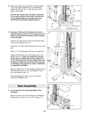
... the cable bolt. Note: The cable bolt is flat (see the inset drawing). Insert the Weight Pin (39) into the threaded hole in the grooves of all three Cables from the Weight Tube (77). When all Pulleys and that both the Cables and the Pulleys move smoothly. Make sure the flat side of Loop 36. Locate and open the parts bag labeled ÒSeat Assembly.Ó Attach one...
... the cable bolt. Note: The cable bolt is flat (see the inset drawing). Insert the Weight Pin (39) into the threaded hole in the grooves of all three Cables from the Weight Tube (77). When all Pulleys and that both the Cables and the Pulleys move smoothly. Make sure the flat side of Loop 36. Locate and open the parts bag labeled ÒSeat Assembly.Ó Attach one...
User Manual
Page 17
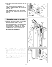
...large chart showing a number of the Pad Tube. Do not tighten the Plain Nuts yet. 42 1 92 91 94 94 93 92 91 96 Bracket 43. Slide a Foam Roller (30) onto each end of exercises. Attach the Left Shroud (96) to the indicated brackets on the Top Frame (1) with two #8 x 3/4Ó Tek Screws (95...x 3/4Ó Black Screws (91), two #10 Flat Washers (92), two #10 Lock Washers (94) and two #10 Plain Nuts (93). Press two 3/4Ó Round Inner Caps (34) into the Leg Lever (29). Slide a Foam Roller (30) onto each end of the unit in the previ- 96 ous step. Attach the Left Shroud (...
...large chart showing a number of the Pad Tube. Do not tighten the Plain Nuts yet. 42 1 92 91 94 94 93 92 91 96 Bracket 43. Slide a Foam Roller (30) onto each end of exercises. Attach the Left Shroud (96) to the indicated brackets on the Top Frame (1) with two #8 x 3/4Ó Tek Screws (95...x 3/4Ó Black Screws (91), two #10 Flat Washers (92), two #10 Lock Washers (94) and two #10 Plain Nuts (93). Press two 3/4Ó Round Inner Caps (34) into the Leg Lever (29). Slide a Foam Roller (30) onto each end of the unit in the previ- 96 ous step. Attach the Left Shroud (...
User Manual
Page 18
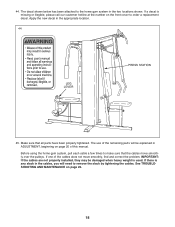
... parts have been properly tightened. Before using the home gym system, pull each cable a few times to remove the slack by tightening the cables. Apply the new decal in the two locations shown. The use of this manual. See TROUBLESHOOTING AND MAINTENANCE on the front cover to the home gym system in the appropriate location. 44 LEG LEVER PRESS STATION 45. 44. The decal shown below has been attached to order a replacement...
... parts have been properly tightened. Before using the home gym system, pull each cable a few times to remove the slack by tightening the cables. Apply the new decal in the two locations shown. The use of this manual. See TROUBLESHOOTING AND MAINTENANCE on the front cover to the home gym system in the appropriate location. 44 LEG LEVER PRESS STATION 45. 44. The decal shown below has been attached to order a replacement...
User Manual
Page 20
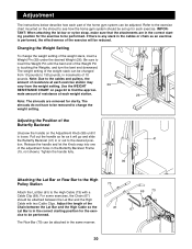
... Cable so the Lat Bar is performed, the effectiveness of the exercise will go and slide the Butterfly Backrest (41) in the Butterfly Backrest Frame (15, not shown). Changing the Weight Setting To change the weight setting. Adjustment The instructions below describe how each part of the home gym system can be performed. Tighten the handle fully. 99 Attaching the Lat Bar or Row Bar to the High Pulley Station Attach the Lat Bar...
... Cable so the Lat Bar is performed, the effectiveness of the exercise will go and slide the Butterfly Backrest (41) in the Butterfly Backrest Frame (15, not shown). Changing the Weight Setting To change the weight setting. Adjustment The instructions below describe how each part of the home gym system can be performed. Tighten the handle fully. 99 Attaching the Lat Bar or Row Bar to the High Pulley Station Attach the Lat Bar...
User Manual
Page 21
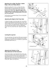
... 70 10 Adjusting the Height of the Press Seat To adjust the height of the Press Seat (13), Unscrew the handle on the Press Backrest Frame (38). For some exercises, the Leg Lever (29) must be locked in the Press Seat Frame (36). Tighten the handle fully. 38 41 Bracket 99 21 Attaching the Lat Bar, Row Bar or Ankle Strap to the Low Pulley Station Attach the Lat Bar (61...
... 70 10 Adjusting the Height of the Press Seat To adjust the height of the Press Seat (13), Unscrew the handle on the Press Backrest Frame (38). For some exercises, the Leg Lever (29) must be locked in the Press Seat Frame (36). Tighten the handle fully. 38 41 Bracket 99 21 Attaching the Lat Bar, Row Bar or Ankle Strap to the Low Pulley Station Attach the Lat Bar (61...

User Manual
Page 22
Adjusting the Weight System for Row Exercises To set up the weight system for row exercises, pull down on the Press Arm Locking Pin (98). weight plates. top weight. Push the Press Arms (46, 47) towards the weight stack and release the Locking Pin so it snaps into one of the holes in this section. 57 Locking Pin (98) 46 41 Weight Resistance Chart This chart shows the approximate weight resistance at each...
Adjusting the Weight System for Row Exercises To set up the weight system for row exercises, pull down on the Press Arm Locking Pin (98). weight plates. top weight. Push the Press Arms (46, 47) towards the weight stack and release the Locking Pin so it snaps into one of the holes in this section. 57 Locking Pin (98) 46 41 Weight Resistance Chart This chart shows the approximate weight resistance at each...

User Manual
Page 23
... you specific legal rights. The warranty extended hereunder is limited to freight damage, abuse, misuse, improper or abnormal usage or repairs not provided by an ICON authorized service center, products used for which vary from the date of purchase. This warranty gives you . The MODEL NUMBER of the product (PROFORM¨ 920 Home Gym System). 3. The KEY NUMBER and DESCRIPTION of the part(s) (see the front cover...
... you specific legal rights. The warranty extended hereunder is limited to freight damage, abuse, misuse, improper or abnormal usage or repairs not provided by an ICON authorized service center, products used for which vary from the date of purchase. This warranty gives you . The MODEL NUMBER of the product (PROFORM¨ 920 Home Gym System). 3. The KEY NUMBER and DESCRIPTION of the part(s) (see the front cover...

User Manual
Page 24
... have become twisted. Re-attach the Pulley and Cable Trap to one Pulley in the Cables before resistance is first used on moving only one or both sets of the High Cable (73). Do not use the home gym system. Tightening the Cables 36 Woven cable, the type of turns into the Weight Tube (77) until the Cables are still too loose. Remove the Cable and re-install it is felt, the...
... have become twisted. Re-attach the Pulley and Cable Trap to one Pulley in the Cables before resistance is first used on moving only one or both sets of the High Cable (73). Do not use the home gym system. Tightening the Cables 36 Woven cable, the type of turns into the Weight Tube (77) until the Cables are still too loose. Remove the Cable and re-install it is felt, the...

User Manual
Page 27
... Roller Pulley Plate 5/8Ó x 1/2Ó Bushing Handgrip 3/4Ó Round Inner Cap 3 1/2Ó Pulley Press Seat Frame Press Seat Upright Press Backrest Frame Weight Pin 1/2Ó Plain Nut Backrest 3/8Ó x 5Ó Bolt 1Ó x 2Ó Inner Cap Cable Trap 5/16Ó x 2 1/2Ó Bolt Right Press Arm Left Press Arm 5/16Ó x 1Ó Bolt 1/4Ó x 1 3/4Ó Screw 3/8Ó Nylon Locknut 1/2Ó Nylon Locknut Key No. Specifications are subject to change without notice. Model No. PFSY92080 R1198A Key No. Part List...
... Roller Pulley Plate 5/8Ó x 1/2Ó Bushing Handgrip 3/4Ó Round Inner Cap 3 1/2Ó Pulley Press Seat Frame Press Seat Upright Press Backrest Frame Weight Pin 1/2Ó Plain Nut Backrest 3/8Ó x 5Ó Bolt 1Ó x 2Ó Inner Cap Cable Trap 5/16Ó x 2 1/2Ó Bolt Right Press Arm Left Press Arm 5/16Ó x 1Ó Bolt 1/4Ó x 1 3/4Ó Screw 3/8Ó Nylon Locknut 1/2Ó Nylon Locknut Key No. Specifications are subject to change without notice. Model No. PFSY92080 R1198A Key No. Part List...

