
Enc Manual
Page 2
... OF CONTENTS WARNING DECAL PLACEMENT 2 IMPORTANT PRECAUTIONS 3 BEFORE YOU BEGIN 6 PART IDENTIFICATION CHART 7 ASSEMBLY 8 HOW TO USE THE TREADMILL 17 HOW TO FOLD AND MOVE THE TREADMILL 25 MAINTENANCE AND TROUBLESHOOTING 26 EXERCISE GUIDELINES 28 PART LIST 30 EXPLODED DRAWING 32 ORDERING REPLACEMENT PARTS ... countries and is missing or illegible, call the telephone number on the front cover of Apple Inc., registered in the location shown. PROFORM is a trademark of this manual and request a free replacement decal. App store is a registered trademark of Google Inc. and other...
... OF CONTENTS WARNING DECAL PLACEMENT 2 IMPORTANT PRECAUTIONS 3 BEFORE YOU BEGIN 6 PART IDENTIFICATION CHART 7 ASSEMBLY 8 HOW TO USE THE TREADMILL 17 HOW TO FOLD AND MOVE THE TREADMILL 25 MAINTENANCE AND TROUBLESHOOTING 26 EXERCISE GUIDELINES 28 PART LIST 30 EXPLODED DRAWING 32 ORDERING REPLACEMENT PARTS ... countries and is missing or illegible, call the telephone number on the front cover of Apple Inc., registered in the location shown. PROFORM is a trademark of this manual and request a free replacement decal. App store is a registered trademark of Google Inc. and other...
Enc Manual
Page 4
... treadmill unattended while it is properly assembled. (See ASSEMBLY on page 8 and HOW TO FOLD AND MOVE THE TREADMILL on the treadmill. 22. Inspect and properly tighten all parts each time the treadmill is not a medical device. Never remove the motor hood unless instructed to move the treadmill ... Keep fingers, hair, and clothing away from the moving the treadmill, make sure that the storage latch is not in use , before performing the maintenance and adjustment procedures described in speed. 23. The treadmill is intended only as an exercise aid in determining heart rate ...
... treadmill unattended while it is properly assembled. (See ASSEMBLY on page 8 and HOW TO FOLD AND MOVE THE TREADMILL on the treadmill. 22. Inspect and properly tighten all parts each time the treadmill is not a medical device. Never remove the motor hood unless instructed to move the treadmill ... Keep fingers, hair, and clothing away from the moving the treadmill, make sure that the storage latch is not in use , before performing the maintenance and adjustment procedures described in speed. 23. The treadmill is intended only as an exercise aid in determining heart rate ...
Enc Manual
Page 6
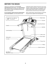
...91 cm) Handrail Latch Assembly Tablet Holder Console Heart Rate Monitor Key/Clip Walking Belt Foot Rail Motor Hood Power Switch Power Cord Wheel Platform Cushions Idler Roller Adjustment Screws 6 If you use the treadmill. The PERFORMANCE 400I treadmill provides an impressive selection of... this manual. For your benefit, read this manual carefully before contacting us assist you for selecting the new PROFORM® PERFORMANCE 400I treadmill.
...91 cm) Handrail Latch Assembly Tablet Holder Console Heart Rate Monitor Key/Clip Walking Belt Foot Rail Motor Hood Power Switch Power Cord Wheel Platform Cushions Idler Roller Adjustment Screws 6 If you use the treadmill. The PERFORMANCE 400I treadmill provides an impressive selection of... this manual. For your benefit, read this manual carefully before contacting us assist you for selecting the new PROFORM® PERFORMANCE 400I treadmill.

Enc Manual
Page 7
The number in the hardware kit, check to identify small parts used for assembly. PART IDENTIFICATION CHART Use the drawings below each drawing is the key number of the part, from the PART LIST near the end of this ... (63)-2 3/8" x 1 3/4" Screw (62)-2 3/8" x 2 1/4" Screw (7)-4 5/16" x 2 1/2" Screw (28)-4 1/4" x 4 1/2" Screw (6)-2 7 Note: If a part is not in parentheses below to see whether it is the quantity used for assembly. The number following the key number is preattached.
The number in the hardware kit, check to identify small parts used for assembly. PART IDENTIFICATION CHART Use the drawings below each drawing is the key number of the part, from the PART LIST near the end of this ... (63)-2 3/8" x 1 3/4" Screw (62)-2 3/8" x 2 1/4" Screw (7)-4 5/16" x 2 1/2" Screw (28)-4 1/4" x 4 1/2" Screw (6)-2 7 Note: If a part is not in parentheses below to see whether it is the quantity used for assembly. The number following the key number is preattached.

Enc Manual
Page 8
...ca/CustomerService/ registration and register your product. 1 • activates your product. 8 ASSEMBLY • Assembly requires two persons. • Place all assembly steps. • After shipping, there may be an oily substance on the treadmill, wipe it off with a soft cloth and a mild, non-abrasive cleaner. •...Customer Service • allows us to notify you of the treadmill. Do not dispose of the packing materials until you do not have Internet access, call Customer Service (see page 7. • Assembly requires the following tools: the included hex keys one Phillips ...
...ca/CustomerService/ registration and register your product. 1 • activates your product. 8 ASSEMBLY • Assembly requires two persons. • Place all assembly steps. • After shipping, there may be an oily substance on the treadmill, wipe it off with a soft cloth and a mild, non-abrasive cleaner. •...Customer Service • allows us to notify you of the treadmill. Do not dispose of the packing materials until you do not have Internet access, call Customer Service (see page 7. • Assembly requires the following tools: the included hex keys one Phillips ...
Enc Manual
Page 12
... slide together easily and snap into place. Then, remove the wire tie (A) from the Upright Wire. With the help of a second person, hold the console assembly (F) near the right Handrail (84) and the left Handrail (not shown). 9 F See the inset drawing. The connec- Connect the Upright Wire (81) to avoid scratching...
... slide together easily and snap into place. Then, remove the wire tie (A) from the Upright Wire. With the help of a second person, hold the console assembly (F) near the right Handrail (84) and the left Handrail (not shown). 9 F See the inset drawing. The connec- Connect the Upright Wire (81) to avoid scratching...
Enc Manual
Page 13
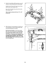
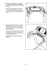
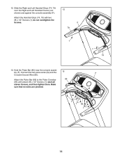
...in step 8 and four 1/4" Star Washers (26); firmly tighten the Screws. 84 81 26 2 90 84 26 2 11. Set the console assembly (F) on the right Handrail (84). Identify the Right Handrail Cover (31). Next, slide the Right Handrail Cover (31) forward until it slides under ...do not fully tighten the Screws. Set the Right Handrail Cover on the Handrails (84). Then, tighten the three #8 x 1/2" Screws (1); 10. Attach the console assembly (F) to the brackets on the Handrails (84) with the four 1/4" x 1/2" Screws (2) that no wires are pinched. 10 F Insert the excess Upright Wire (...
...in step 8 and four 1/4" Star Washers (26); firmly tighten the Screws. 84 81 26 2 90 84 26 2 11. Set the console assembly (F) on the right Handrail (84). Identify the Right Handrail Cover (31). Next, slide the Right Handrail Cover (31) forward until it slides under ...do not fully tighten the Screws. Set the Right Handrail Cover on the Handrails (84). Then, tighten the three #8 x 1/2" Screws (1); 10. Attach the console assembly (F) to the brackets on the Handrails (84) with the four 1/4" x 1/2" Screws (2) that no wires are pinched. 10 F Insert the excess Upright Wire (...
Enc Manual
Page 14
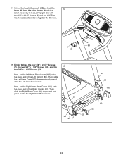
... the Console Ground Wire (58). Make sure that no wires are pinched. 13 85 F G 93 1 1 58 1 14 Hold the Pulse Bar (85) near the console assembly (F). start all eleven Screws, and then tighten them. 12. Attach the Handrail Grips (74, 79) with eleven #8 x 1/2" Screws (1); Attach the Pulse Bar (85) to the... two #8 x 1/2" Screws (1); Slide the Right and Left Handrail Grips (74, 79) over the Right and Left Handrail Covers (not 12 shown) and against the console assembly (F). do not overtighten the Screws.
... the Console Ground Wire (58). Make sure that no wires are pinched. 13 85 F G 93 1 1 58 1 14 Hold the Pulse Bar (85) near the console assembly (F). start all eleven Screws, and then tighten them. 12. Attach the Handrail Grips (74, 79) with eleven #8 x 1/2" Screws (1); Attach the Pulse Bar (85) to the... two #8 x 1/2" Screws (1); Slide the Right and Left Handrail Grips (74, 79) over the Right and Left Handrail Covers (not 12 shown) and against the console assembly (F). do not overtighten the Screws.
Enc Manual
Page 15
Orient the Latch Assembly (52) so that the knob (H) is on the side shown. Firmly tighten the four 3/8" x 2 1/4" Screws (7), the two 3/8" x 1 3/4" Screws (62), and the 15 two 3/8" x 1 1/4" Screws (63). H ... the Right Inner Base Cover. 83 62 63 90 7 89 82 100 63 7 62 101 15 do not overtighten the Screws. Attach the 14 Latch Assembly to the Left Upright (89) with two 1/4" x 4 1/2" Screws (6) and two 1/4" Star Washers (26); Next, set the Left Inner Base Cover (100) onto the lower end...
Orient the Latch Assembly (52) so that the knob (H) is on the side shown. Firmly tighten the four 3/8" x 2 1/4" Screws (7), the two 3/8" x 1 3/4" Screws (62), and the 15 two 3/8" x 1 1/4" Screws (63). H ... the Right Inner Base Cover. 83 62 63 90 7 89 82 100 63 7 62 101 15 do not overtighten the Screws. Attach the 14 Latch Assembly to the Left Upright (89) with two 1/4" x 4 1/2" Screws (6) and two 1/4" Star Washers (26); Next, set the Left Inner Base Cover (100) onto the lower end...
Enc Manual
Page 16
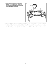
...a secure place; the hex key is used to the console, keep the treadmill out of plastic on the treadmill decals, remove the plastic. To protect the floor or carpet, place a mat under the treadmill. Note: Extra hardware may be included. 16 If there are properly tightened ...before you use the treadmill. Attach the Tablet Holder (25) to the console assembly (F) with four #8 x 5/8" Screws (8); 16 start all parts are sheets...
...a secure place; the hex key is used to the console, keep the treadmill out of plastic on the treadmill decals, remove the plastic. To protect the floor or carpet, place a mat under the treadmill. Note: Extra hardware may be included. 16 If there are properly tightened ...before you use the treadmill. Attach the Tablet Holder (25) to the console assembly (F) with four #8 x 5/8" Screws (8); 16 start all parts are sheets...
Enc Manual
Page 30
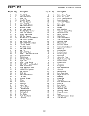
... 1 83 1 84 2 85 1 86 2 87 1 88 1 89 1 90 1 91 2 92 4 93 1 94 1 95 7 96 2 Description Drive Roller/Pulley Base Pad Spacer 9/32" Plastic Bushing Latch Assembly 1/4" x 1 1/4" Screw Drive Motor Motor Belt Frame Left Rear Foot Console Ground Wire Rubber Cushion Right Foot Rail Idler Roller 3/8" x 1 3/4" Screw 3/8" x 1 1/4" Screw Console Base Motor Hood...
... 1 83 1 84 2 85 1 86 2 87 1 88 1 89 1 90 1 91 2 92 4 93 1 94 1 95 7 96 2 Description Drive Roller/Pulley Base Pad Spacer 9/32" Plastic Bushing Latch Assembly 1/4" x 1 1/4" Screw Drive Motor Motor Belt Frame Left Rear Foot Console Ground Wire Rubber Cushion Right Foot Rail Idler Roller 3/8" x 1 3/4" Screw 3/8" x 1 1/4" Screw Console Base Motor Hood...


