
Owner/User Manual
Page 1
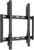
... panel solutions Tilt Wall Mount for LCD, Plasma, and LED Displays Instruction Manual MST46BKR Fits TVs 26"- 46" Maximum Load Capacity - 99 lb (45 kg) Specifications Display Size: Maximum Load: Mounting Pattern: Tilt Range: Profile: Box contents Upper Wall Plate (x1) Lower Wall Plate (x1) Left Plastic Side (x1) Right Plastic Side (x1) 26" to install this mount alone under...
... panel solutions Tilt Wall Mount for LCD, Plasma, and LED Displays Instruction Manual MST46BKR Fits TVs 26"- 46" Maximum Load Capacity - 99 lb (45 kg) Specifications Display Size: Maximum Load: Mounting Pattern: Tilt Range: Profile: Box contents Upper Wall Plate (x1) Lower Wall Plate (x1) Left Plastic Side (x1) Right Plastic Side (x1) 26" to install this mount alone under...
Owner/User Manual
Page 2
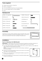
..., this mount must be capable of supporting the combined weight of the marked studs. The studs must use the center of the connections as it may result in the wall using the template as shown in the illustration (see Fig. 2). 4. Fig.1 Installation Part 1A - Make sure the template is level. 3. Tools required Phillips-Head Screwdriver or Screw Gun Electric...
..., this mount must be capable of supporting the combined weight of the marked studs. The studs must use the center of the connections as it may result in the wall using the template as shown in the illustration (see Fig. 2). 4. Fig.1 Installation Part 1A - Make sure the template is level. 3. Tools required Phillips-Head Screwdriver or Screw Gun Electric...
Owner/User Manual
Page 3
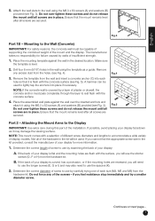
...the back of the installation. Fig.3 Part 1B - Place the mounting template against the wall over -tighten these screws and do not release the mount until all screws are in the kit will be used to accommodate a wide variety of the mount and the display. ...supporting the combined weight of display models. Attach the wall plate to rest flush with the surface, you cannot find the appropriate screw size in the kit provided, consult the manufacturer of the hardware in place. Place the assembled wall plate against the wall in the wall using the M6.3 x 63 screws...
...the back of the installation. Fig.3 Part 1B - Place the mounting template against the wall over -tighten these screws and do not release the mount until all screws are in the kit will be used to accommodate a wide variety of the mount and the display. ...supporting the combined weight of display models. Attach the wall plate to rest flush with the surface, you cannot find the appropriate screw size in the kit provided, consult the manufacturer of the hardware in place. Place the assembled wall plate against the wall in the wall using the M6.3 x 63 screws...

Owner/User Manual
Page 4
...mount arms are using the screws identified in the hardware kit. 2. Otherwise, the tilt function cannot be tightened using the longer screws on a display with a knife or looped back and tucked into the rubber ring located on each tab. 5. With the help of your display they can be accessed. 3. B. You should not be trimmed...gently pushing up on the mount. Do not release the display until the mount arms have successfully engaged by pulling them down and then forward (away from the wall) to use a spacer if necessary. If the plastic tabs hang below the bottom of another...
...mount arms are using the screws identified in the hardware kit. 2. Otherwise, the tilt function cannot be tightened using the longer screws on a display with a knife or looped back and tucked into the rubber ring located on each tab. 5. With the help of your display they can be accessed. 3. B. You should not be trimmed...gently pushing up on the mount. Do not release the display until the mount arms have successfully engaged by pulling them down and then forward (away from the wall) to use a spacer if necessary. If the plastic tabs hang below the bottom of another...

Owner/User Manual
Page 5
...to the desired position, and then re-tighten the tilt mechanisms. If your display is in place and loosen the tilt mechanisms using the long Allen key (L) from the hardware kit (see Fig. 9). To change the tilt angle of your mount with a dry cloth. Do not release the display ...until both tilt mechanisms are firmly tightened. 2. Fig.9 Re-tighten as needed. 5 English Operation and adjustment 1. Inspect all screws ...
...to the desired position, and then re-tighten the tilt mechanisms. If your display is in place and loosen the tilt mechanisms using the long Allen key (L) from the hardware kit (see Fig. 9). To change the tilt angle of your mount with a dry cloth. Do not release the display ...until both tilt mechanisms are firmly tightened. 2. Fig.9 Re-tighten as needed. 5 English Operation and adjustment 1. Inspect all screws ...