

Operation Manual
Page 1
WARNING: To reduce the risk of operation, and operator safety. SAVE THIS MANUAL FOR FUTURE REFERENCE When properly cared for, it will give you for dependability, ease of injury, the user must read and understand the operator's manual before using this product. OPERATOR'S MANUAL 3 in . BELT SANDER VARIABLE SPEED DOUBLE INSULATED R2720 Your belt sander has been engineered and manufactured to our high standard for buying a RIDGID product. Thank you years of rugged, trouble-free performance. x 21 in .
WARNING: To reduce the risk of operation, and operator safety. SAVE THIS MANUAL FOR FUTURE REFERENCE When properly cared for, it will give you for dependability, ease of injury, the user must read and understand the operator's manual before using this product. OPERATOR'S MANUAL 3 in . BELT SANDER VARIABLE SPEED DOUBLE INSULATED R2720 Your belt sander has been engineered and manufactured to our high standard for buying a RIDGID product. Thank you years of rugged, trouble-free performance. x 21 in .

Operation Manual
Page 2
Safety, performance, and dependability have been given top priority in the design of this product making its use more pleasant and enjoyable. TABLE OF CONTENTS n Introduction ...2 �n General Safety Rules ...3-4 �n Specific Safety Rules...4 �n Symbols...5-6 �n Electrical ...7 �n Features...8-9 �n Assembly ...9 �n Operation...10-15 �n Maintenance ...16-17 �n Warranty ...19 �n Parts Ordering / Service ...20 INTRODUCTION This tool has many features for making it easy to maintain and operate. 2
Safety, performance, and dependability have been given top priority in the design of this product making its use more pleasant and enjoyable. TABLE OF CONTENTS n Introduction ...2 �n General Safety Rules ...3-4 �n Specific Safety Rules...4 �n Symbols...5-6 �n Electrical ...7 �n Features...8-9 �n Assembly ...9 �n Operation...10-15 �n Maintenance ...16-17 �n Warranty ...19 �n Parts Ordering / Service ...20 INTRODUCTION This tool has many features for making it easy to maintain and operate. 2

Operation Manual
Page 3
... if your body is an increased risk of the power tool in unexpected situations. SAVE THESE INSTRUCTIONS WORK AREA SAFETY elry. ELECTRICAL SAFETY n Power tool plugs must be caught in any adjusting key or wrench before turning the power tool on a ladder or unstable support. Never modify the plug in moving parts. Do not use the power tool if the switch does not turn it was designed. There is earthed or grounded...
... if your body is an increased risk of the power tool in unexpected situations. SAVE THESE INSTRUCTIONS WORK AREA SAFETY elry. ELECTRICAL SAFETY n Power tool plugs must be caught in any adjusting key or wrench before turning the power tool on a ladder or unstable support. Never modify the plug in moving parts. Do not use the power tool if the switch does not turn it was designed. There is earthed or grounded...

Operation Manual
Page 4
... operation where the cutting tool may use this power tool. Read operator's manual carefully. Following this power tool, loan them to instruct others who may contact hidden wiring or its operation. Use of unauthorized parts or failure to follow Maintenance instructions may affect its own cord. n Save these chemicals are: • lead from lead-based paints, • crystalline silica from lumber before using this manual. GENERAL SAFETY RULES SERVICE n Have your power tool serviced by a qualified repair...
... operation where the cutting tool may use this power tool. Read operator's manual carefully. Following this power tool, loan them to instruct others who may contact hidden wiring or its operation. Use of unauthorized parts or failure to follow Maintenance instructions may affect its own cord. n Save these chemicals are: • lead from lead-based paints, • crystalline silica from lumber before using this manual. GENERAL SAFETY RULES SERVICE n Have your power tool serviced by a qualified repair...
Operation Manual
Page 5
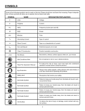
... keep your hands away from the blade will result in serious personal injury. SYMBOL NAME DESIGNATION/EXPLANATION V Volts Voltage A Amperes Current Hz Hertz Frequency (cycles per second) W Watt Power min Minutes Time Alternating Current Type of current no .../min Direct Current No Load Speed Class II Construction Per Minute Type or a characteristic of current Rotational speed, at no load Double-insulated...
... keep your hands away from the blade will result in serious personal injury. SYMBOL NAME DESIGNATION/EXPLANATION V Volts Voltage A Amperes Current Hz Hertz Frequency (cycles per second) W Watt Power min Minutes Time Alternating Current Type of current no .../min Direct Current No Load Speed Class II Construction Per Minute Type or a characteristic of current Rotational speed, at no load Double-insulated...
Operation Manual
Page 6
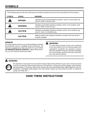
...power tool can result in foreign objects being thrown into your nearest AUTHORIZED SERVICE CENTER for repair...operator's manual. WARNING: The operation of risk associated with ANSI Z87.1. SAVE THESE INSTRUCTIONS 6 Before beginning power tool operation, always wear safety goggles, safety glasses with side shields. Always use this product until you return the product to comply with this operator's manual and review frequently for use only identical replacement parts. When servicing, use over eyeglasses or standard safety glasses with side shields, or a full face shield when needed...
...power tool can result in foreign objects being thrown into your nearest AUTHORIZED SERVICE CENTER for repair...operator's manual. WARNING: The operation of risk associated with ANSI Z87.1. SAVE THESE INSTRUCTIONS 6 Before beginning power tool operation, always wear safety goggles, safety glasses with side shields. Always use this product until you return the product to comply with this operator's manual and review frequently for use only identical replacement parts. When servicing, use over eyeglasses or standard safety glasses with side shields, or a full face shield when needed...

Operation Manual
Page 7
... with protecting insulation. WARNING: Check extension cords before each use original factory replacement parts when servicing. Observe all normal safety precautions to determine the minimum wire size required in an extension cord. If your nearest authorized service center for loose or exposed wires and cut or worn insulation. **Ampere rating (on tool data plate) 0-2.0 2.1-3.4 3.5-5.0 5.1-7.0 7.1-12.0 12.1-16.0 Cord Length Wire Size (A.W.G.) 25' 16 16 16 16 14...
... with protecting insulation. WARNING: Check extension cords before each use original factory replacement parts when servicing. Observe all normal safety precautions to determine the minimum wire size required in an extension cord. If your nearest authorized service center for loose or exposed wires and cut or worn insulation. **Ampere rating (on tool data plate) 0-2.0 2.1-3.4 3.5-5.0 5.1-7.0 7.1-12.0 12.1-16.0 Cord Length Wire Size (A.W.G.) 25' 16 16 16 16 14...
Operation Manual
Page 8
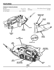
Sanding Surface 17.5 sq. VARIABLE SPEED CONTROL DIAL LOCK-ON BUTTON SWITCH TRIGGER TRACKING KNOB HEX KEY STORAGE DUST COLLECTION BAG HEX KEY HEX KEY STORAGE REAR HANDLE LIGHTED PLUG ADJUSTABLE FRONT HANDLE DRIVE ROLLER BELT TENSION RELEASE LEVER FRONT ROLLER 8 SANDING BELT Fig. 1 x 21 in . in . FEATURES PRODUCT SPECIFICATIONS Belt Size 3 in. Input 120 V, 60 Hz, AC only, 10.0 Amps Net Weight 10.5 lbs. No Load Speed 800 - 1,500/min.
Sanding Surface 17.5 sq. VARIABLE SPEED CONTROL DIAL LOCK-ON BUTTON SWITCH TRIGGER TRACKING KNOB HEX KEY STORAGE DUST COLLECTION BAG HEX KEY HEX KEY STORAGE REAR HANDLE LIGHTED PLUG ADJUSTABLE FRONT HANDLE DRIVE ROLLER BELT TENSION RELEASE LEVER FRONT ROLLER 8 SANDING BELT Fig. 1 x 21 in . in . FEATURES PRODUCT SPECIFICATIONS Belt Size 3 in. Input 120 V, 60 Hz, AC only, 10.0 Amps Net Weight 10.5 lbs. No Load Speed 800 - 1,500/min.

Operation Manual
Page 9
... accessories from A (slowest) to lock the switch trigger in the packing list are replaced. ERGONOMIC DESIGN The design provides for ease of time. LIGHTED PLUG The lighted plug helps to a minimum. SWITCH TRIGGER To turn your sander OFF. POWER CORD The 12-foot cord has a built-in accidental starting and possible serious personal injury. 9 LOCK-ON BUTTON The lock-on allows you to F (fastest). PACKING LIST Variable Speed Belt Sander Handle Assembly (Screw, Hex Wrench, Handle) Dust Collection Bag Sanding Belt Operator's Manual...
... accessories from A (slowest) to lock the switch trigger in the packing list are replaced. ERGONOMIC DESIGN The design provides for ease of time. LIGHTED PLUG The lighted plug helps to a minimum. SWITCH TRIGGER To turn your sander OFF. POWER CORD The 12-foot cord has a built-in accidental starting and possible serious personal injury. 9 LOCK-ON BUTTON The lock-on allows you to F (fastest). PACKING LIST Variable Speed Belt Sander Handle Assembly (Screw, Hex Wrench, Handle) Dust Collection Bag Sanding Belt Operator's Manual...

Operation Manual
Page 10
... tool. Then use finer grit for the purposes listed below for power sanding. Failure to do the best job. The use any attachments or accessories not recommended by the coarser grit. SELECTING SANDING BELTS Selecting the correct size and type of the tool resulting in achieving a high quality sanded finish. SETTING THE BELT SANDER SPEED Refer to inflict serious injury. MATERIAL UNDRESSED LUMBER SOFTWOOD CHIPBOARD LUMBER RUST REMOVAL...
... tool. Then use finer grit for the purposes listed below for power sanding. Failure to do the best job. The use any attachments or accessories not recommended by the coarser grit. SELECTING SANDING BELTS Selecting the correct size and type of the tool resulting in achieving a high quality sanded finish. SETTING THE BELT SANDER SPEED Refer to inflict serious injury. MATERIAL UNDRESSED LUMBER SOFTWOOD CHIPBOARD LUMBER RUST REMOVAL...

Operation Manual
Page 11
... previous speed setting once the switch trigger is a feature whereby the motor gradually ramps up to allow two-handed operation which aids in the sanding of belt speed. n To turn off , or if it were not properly adjusted, your fingers rest over the front or right edge of operation the sander has an adjustable front handle and a stationary rear handle. Refer to run off the sander: Release the switch trigger. VARIABLE SPEED CONTROL...
... previous speed setting once the switch trigger is a feature whereby the motor gradually ramps up to allow two-handed operation which aids in the sanding of belt speed. n To turn off , or if it were not properly adjusted, your fingers rest over the front or right edge of operation the sander has an adjustable front handle and a stationary rear handle. Refer to run off the sander: Release the switch trigger. VARIABLE SPEED CONTROL...

Operation Manual
Page 12
... and spring mechanism at all times. n Install sanding belt; TO ADJUST FRONT HANDLE See Figure 7. SANDING BELT LIFT BELT TENSION RELEASE LEVER TO REMOVE SANDING BELT WARNING: Keep hands and fingers clear of the sander). n Unplug the belt sander. n Unplug the sander. NOTE: Match the arrow on the rear handle bridge. n Return hex key to secure the sanding belt. OPERATION TO INSTALL/CHANGE SANDING BELT See Figures 5 - 6. CAUTION: If the sanding belt is not a bidirectional belt, ensure that of sander. n Lower tension release lever...
... and spring mechanism at all times. n Install sanding belt; TO ADJUST FRONT HANDLE See Figure 7. SANDING BELT LIFT BELT TENSION RELEASE LEVER TO REMOVE SANDING BELT WARNING: Keep hands and fingers clear of the sander). n Unplug the belt sander. n Unplug the sander. NOTE: Match the arrow on the rear handle bridge. n Return hex key to secure the sanding belt. OPERATION TO INSTALL/CHANGE SANDING BELT See Figures 5 - 6. CAUTION: If the sanding belt is not a bidirectional belt, ensure that of sander. n Lower tension release lever...

Operation Manual
Page 13
.... Removal rate will damage the front roller. To lock-on button. n Release the lock-on feature allows you to operate the sander for contour sanding. SWITCH TRIGGER Fig. 8 WARNING: Keep a firm grip on the drive roller and front roller. n Clogged sanding belts. Locking the switch trigger on feature immediately. Use a coarser belt when heavy sanding is accidentally disconnected from the power supply, disengage the lock-on allows you to suddenly stop the sander. Sanding...
.... Removal rate will damage the front roller. To lock-on button. n Release the lock-on feature allows you to operate the sander for contour sanding. SWITCH TRIGGER Fig. 8 WARNING: Keep a firm grip on the drive roller and front roller. n Clogged sanding belts. Locking the switch trigger on feature immediately. Use a coarser belt when heavy sanding is accidentally disconnected from the power supply, disengage the lock-on allows you to suddenly stop the sander. Sanding...

Operation Manual
Page 14
... is for adjustments only. If the sanding belt runs inward, slowly turn the tracking knob counterclockwise. They could get thrown from moving parts and foreign objects could result in contact with the outer edge of the sander. When correctly adjusted, the outer edge of sanding belt. n With sander positioned as shown below, pull switch trigger and release immediately. WARNING: Keep hands and fingers away from sander causing injury...
... is for adjustments only. If the sanding belt runs inward, slowly turn the tracking knob counterclockwise. They could get thrown from moving parts and foreign objects could result in contact with the outer edge of the sander. When correctly adjusted, the outer edge of sanding belt. n With sander positioned as shown below, pull switch trigger and release immediately. WARNING: Keep hands and fingers away from sander causing injury...

Operation Manual
Page 15
... the sander. n To remove the dust bag, turn clockwise and pull off. Also follow the recommendations of fire, always empty the dust bag frequently while sanding and never store or leave a sander without dust bag properly installed. DUST BAG See Figure 11. n Turn the dust bag counterclockwise to power supply before installing dust bag. TURN TO SECURE DUST BAG DUST EXHAUST DUST BAG OPENING GROOVE WARNING: Do not use the sander...
... the sander. n To remove the dust bag, turn clockwise and pull off. Also follow the recommendations of fire, always empty the dust bag frequently while sanding and never store or leave a sander without dust bag properly installed. DUST BAG See Figure 11. n Turn the dust bag counterclockwise to power supply before installing dust bag. TURN TO SECURE DUST BAG DUST EXHAUST DUST BAG OPENING GROOVE WARNING: Do not use the sander...

Operation Manual
Page 16
... their use only identical RIDGID replacement parts. MAINTENANCE WARNING: When servicing use . Use clean cloths to bearings, brushes, commutators, etc. Chemicals can damage, weaken or destroy plastic which may be damaged by reversing the steps listed above. Therefore, no further lubrication is equipped with side shields during power tool operation or when blowing dust. Make sure curvature of brush matches curvature of carbon remaining. Replace both brush assemblies when...
... their use only identical RIDGID replacement parts. MAINTENANCE WARNING: When servicing use . Use clean cloths to bearings, brushes, commutators, etc. Chemicals can damage, weaken or destroy plastic which may be damaged by reversing the steps listed above. Therefore, no further lubrication is equipped with side shields during power tool operation or when blowing dust. Make sure curvature of brush matches curvature of carbon remaining. Replace both brush assemblies when...

Operation Manual
Page 17
... of installing a new timing belt. n Holding the timing belt as shown in place. n Force old timing belt from large pulley with a screwdriver and remove it is worn out, simply cut the old timing belt and remove. SCREW BELT COVER SMALL PULLEY LARGE PULLEY TIMING BELT SANDER SHOWN WITH DUST BAG AND SANDING BELT REMOVED Fig. 13 APPLY PRESSURE HERE AND TURN LARGE PULLEY Fig. 14 17 n Unplug the sander. MAINTENANCE TIMING BELT REPLACEMENT...
... of installing a new timing belt. n Holding the timing belt as shown in place. n Force old timing belt from large pulley with a screwdriver and remove it is worn out, simply cut the old timing belt and remove. SCREW BELT COVER SMALL PULLEY LARGE PULLEY TIMING BELT SANDER SHOWN WITH DUST BAG AND SANDING BELT REMOVED Fig. 13 APPLY PRESSURE HERE AND TURN LARGE PULLEY Fig. 14 17 n Unplug the sander. MAINTENANCE TIMING BELT REPLACEMENT...
Operation Manual
Page 19
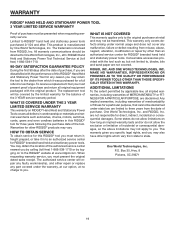
... of the tool. RIDGID, INC. ADDITIONAL LIMITATIONS To the extent permitted by logging on how long an implied warranty lasts and/or do not allow the exclusion or limitation of incidental or consequential damages, so the above limitations may not apply to , blades, bits and sand paper are dissatisfied with the tool such as brushes, chucks, motors, switches, cords, gears and even cordless batteries in...
... of the tool. RIDGID, INC. ADDITIONAL LIMITATIONS To the extent permitted by logging on how long an implied warranty lasts and/or do not allow the exclusion or limitation of incidental or consequential damages, so the above limitations may not apply to , blades, bits and sand paper are dissatisfied with the tool such as brushes, chucks, motors, switches, cords, gears and even cordless batteries in...

Operation Manual
Page 20
... ordering repair parts, always give the following information: Model No. Be sure to the motor housing. The model number of the authorized service center nearest you call 1-866-539-1710 or visit us online at www.ridgid.com. R2720 Serial No. 983000-639 3-24-06 (REV:01) 20 OPERATOR'S MANUAL 3 in the space provided below. BELT SANDER VARIABLE SPEED DOUBLE INSULATED R2720 Customer Service Information: For parts or service, contact...
... ordering repair parts, always give the following information: Model No. Be sure to the motor housing. The model number of the authorized service center nearest you call 1-866-539-1710 or visit us online at www.ridgid.com. R2720 Serial No. 983000-639 3-24-06 (REV:01) 20 OPERATOR'S MANUAL 3 in the space provided below. BELT SANDER VARIABLE SPEED DOUBLE INSULATED R2720 Customer Service Information: For parts or service, contact...

Repair Sheet
Page 3
...DESCRIPTION QTY CONTACT PLATE STOPPER 1 HEX NUT (M8 1 TIMING BELT 1 DRIVEN PULLEY 1 WASHER 1 BACKING PAD 1 SCREW (M4 x 6 mm TORX 2 WAVY WASHER 1 SCREW (M4 x 12 mm TORX FLAT HD.).. 2 MAIN HOUSING SUPPORT ASSEMBLY 1 IDLE ARM SUPPORT 1 RELEASE LEVER ASSEMBLY 1 IDLE ROLLER SHAFT ASSEMBLY.......... 1 FELT SEAL 1 WASHER 1 DRIVE ROLLER ASSEMBLY 1 MAIN HOUSING COVER 1 SCREW (M4 x 16 mm 2 CORD CLAMP 1 WASHER 1 POWER CORD ASSEMBLY 1 BEND RELIEF 1 SANDING BELT 1 SWITCH ASSEMBLY 1 LOGO LABEL 1 SCREW (M4 x 8 mm 1 SPEED CONTROL DIAL 1 KEY P/N 55 690551001...
...DESCRIPTION QTY CONTACT PLATE STOPPER 1 HEX NUT (M8 1 TIMING BELT 1 DRIVEN PULLEY 1 WASHER 1 BACKING PAD 1 SCREW (M4 x 6 mm TORX 2 WAVY WASHER 1 SCREW (M4 x 12 mm TORX FLAT HD.).. 2 MAIN HOUSING SUPPORT ASSEMBLY 1 IDLE ARM SUPPORT 1 RELEASE LEVER ASSEMBLY 1 IDLE ROLLER SHAFT ASSEMBLY.......... 1 FELT SEAL 1 WASHER 1 DRIVE ROLLER ASSEMBLY 1 MAIN HOUSING COVER 1 SCREW (M4 x 16 mm 2 CORD CLAMP 1 WASHER 1 POWER CORD ASSEMBLY 1 BEND RELIEF 1 SANDING BELT 1 SWITCH ASSEMBLY 1 LOGO LABEL 1 SCREW (M4 x 8 mm 1 SPEED CONTROL DIAL 1 KEY P/N 55 690551001...


