
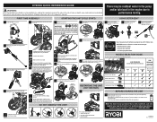
Quick Reference Guide
Page 1
... oil fill hole. Only use E15 or E85 fuel in the engine due to the pump (see page 12). This is level. This will activate soap injector at 1-877-617-3501. If the engine does not start: • check for detergent (see page 8). To add, follow the instructions provided by the Pump Protector manufacturer. ON/OFF SWITCH (ON) Turn the fuel valve to adjust choke position; • try starting...
... oil fill hole. Only use E15 or E85 fuel in the engine due to the pump (see page 12). This is level. This will activate soap injector at 1-877-617-3501. If the engine does not start: • check for detergent (see page 8). To add, follow the instructions provided by the Pump Protector manufacturer. ON/OFF SWITCH (ON) Turn the fuel valve to adjust choke position; • try starting...
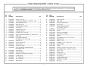
Parts Diagram
Page 3
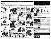
... 940889002 49 940872003 Soap Tank Cap 1 Soap Tank 1 Chemical Siphon Tube 1 Hose (25 ft 1 Trigger Handle Assembly (Inc. KEY PART NO. RYOBI PRESSURE WASHER − ITEM NO. Always mention the model number in 2 Handle Assembly 1 Hose and Nozzle Holder Assembly (Inc. Key Nos. 13, 37 and 42 1 Rubber Foot 1 Handle Spring Clip 2 Wheel (12 in all correspondence regarding your PRESSURE WASHER or when ordering replacement parts. Key No. 14)........ 1 EMC...
... 940889002 49 940872003 Soap Tank Cap 1 Soap Tank 1 Chemical Siphon Tube 1 Hose (25 ft 1 Trigger Handle Assembly (Inc. KEY PART NO. RYOBI PRESSURE WASHER − ITEM NO. Always mention the model number in 2 Handle Assembly 1 Hose and Nozzle Holder Assembly (Inc. Key Nos. 13, 37 and 42 1 Rubber Foot 1 Handle Spring Clip 2 Wheel (12 in all correspondence regarding your PRESSURE WASHER or when ordering replacement parts. Key No. 14)........ 1 EMC...
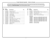
Parts Diagram
Page 4
...-H-PW) High Altitude Kit (6000-8000FT) (R210-H-PW) High Altitude Kit (3000-6000FT) (R210-S-PW) High Altitude Kit (6000-8000FT) (R210-S-PW) Operator's Manual Quick Start Guide 4 NUMBER DESCRIPTION QTY 64 660938003 Bolt (M5 x 20 mm 1 65 310704024 Main Frame Assembly (Right, Inc. Always mention the model number in all correspondence regarding your PRESSURE WASHER or when ordering replacement parts. NUMBER DESCRIPTION QTY 50 940708018 Engine Switch Label 1 51 940647084 Fuel Valve Label...
...-H-PW) High Altitude Kit (6000-8000FT) (R210-H-PW) High Altitude Kit (3000-6000FT) (R210-S-PW) High Altitude Kit (6000-8000FT) (R210-S-PW) Operator's Manual Quick Start Guide 4 NUMBER DESCRIPTION QTY 64 660938003 Bolt (M5 x 20 mm 1 65 310704024 Main Frame Assembly (Right, Inc. Always mention the model number in all correspondence regarding your PRESSURE WASHER or when ordering replacement parts. NUMBER DESCRIPTION QTY 50 940708018 Engine Switch Label 1 51 940647084 Fuel Valve Label...
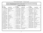
Parts Diagram
Page 6
... Air Cleaner 1 Nut 5 Exhaust Gasket 1 Nut 2 Muffler Assembly 1 Fuel Tank 1 Fuel Strainer 1 Fuel Tank Cover 1 Fuel Tank Oil Outlet Assembly 1 Collar 2 Fuel Tube 1 Bolt 1 Governor Support Assembly.......1 Rubber Jacket 1 Flywheel Nut 1 Starter Pulley 1 Impeller 1 Flywheel Assembly 1 Bolt 2 Ignition Coil 1 Throttle Control Assembly...........1 Governor Spring 1 Governor Rod 1 Throttle Valve Return Spring........1 Clip 1 Woodruff Key 1 Rollover Valve 1 Clamp 1 Fuel Hose 1 6 RY80588 The model number will be found on a label attached to the engine. PARTS LIST KEY PART...
... Air Cleaner 1 Nut 5 Exhaust Gasket 1 Nut 2 Muffler Assembly 1 Fuel Tank 1 Fuel Strainer 1 Fuel Tank Cover 1 Fuel Tank Oil Outlet Assembly 1 Collar 2 Fuel Tube 1 Bolt 1 Governor Support Assembly.......1 Rubber Jacket 1 Flywheel Nut 1 Starter Pulley 1 Impeller 1 Flywheel Assembly 1 Bolt 2 Ignition Coil 1 Throttle Control Assembly...........1 Governor Spring 1 Governor Rod 1 Throttle Valve Return Spring........1 Clip 1 Woodruff Key 1 Rollover Valve 1 Clamp 1 Fuel Hose 1 6 RY80588 The model number will be found on a label attached to the engine. PARTS LIST KEY PART...
Operation Manual
Page 6
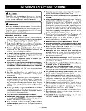
... switch replaced by a qualified service center to comply with any solvents to this manual. „ Check damaged parts. Never use . IMPORTANT SAFETY INSTRUCTIONS DANGER: Risk of fire and serious burns: Never remove fuel cap when unit is running unattended. Failure to rain. Always use in damp or wet locations or expose to follow all instructions listed below may affect its intended function. Keep work area before turning...
... switch replaced by a qualified service center to comply with any solvents to this manual. „ Check damaged parts. Never use . IMPORTANT SAFETY INSTRUCTIONS DANGER: Risk of fire and serious burns: Never remove fuel cap when unit is running unattended. Failure to rain. Always use in damp or wet locations or expose to follow all instructions listed below may affect its intended function. Keep work area before turning...
Operation Manual
Page 7
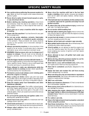
...; Loosen fuel cap slowly to release pressure and to make any adjustments while the engine (motor) is running . „ Never start the engine, but move when the trigger is pulled due to cool for 30 minutes and drain fuel from the unit. „ Store fuel in a cool, well-ventilated area, safely away from spark and/or flame-producing equipment. „ Store fuel in a vehicle. „ When servicing use...
...; Loosen fuel cap slowly to release pressure and to make any adjustments while the engine (motor) is running . „ Never start the engine, but move when the trigger is pulled due to cool for 30 minutes and drain fuel from the unit. „ Store fuel in a cool, well-ventilated area, safely away from spark and/or flame-producing equipment. „ Store fuel in a vehicle. „ When servicing use...
Operation Manual
Page 8
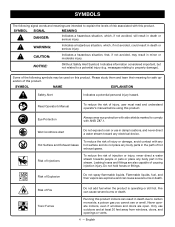
... related to explain the levels of injury, user must read and understand operator's manual before using this product. Always wear eye protection with this product indoors can cause severe burns or death. Leaking hoses and fittings are open. Running this product. Risk of Fire Toxic Fumes Do not add fuel when the product is operating or still hot.
... related to explain the levels of injury, user must read and understand operator's manual before using this product. Always wear eye protection with this product indoors can cause severe burns or death. Leaking hoses and fittings are open. Running this product. Risk of Fire Toxic Fumes Do not add fuel when the product is operating or still hot.
Operation Manual
Page 10
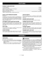
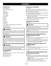
... high pressure hose is pulled to start the engine. STARTER GRIP AND ROPE The starter grip and rope is rolled, hang it on /off . TRIGGER HANDLE The trigger handle has a gripping surface that provides added control of a product that all operating features and safety rules. Make sure that may have carefully inspected and satisfactorily operated the tool. Use of the spray wand and helps reduce fatigue. If any parts...
... high pressure hose is pulled to start the engine. STARTER GRIP AND ROPE The starter grip and rope is rolled, hang it on /off . TRIGGER HANDLE The trigger handle has a gripping surface that provides added control of a product that all operating features and safety rules. Make sure that may have carefully inspected and satisfactorily operated the tool. Use of the spray wand and helps reduce fatigue. If any parts...
Operation Manual
Page 11
..., which can cause the trigger handle to leak during use , pull the handle up until the lock button snaps through the locking slot to secure the spray wand in -1 Nozzle Storage Panel Screws (4) Nuts (4) Wheels (2) Axles (2) Hitch Pins (2) Washers (2) 4-Cycle Engine Lubricant (SAE 30 or SAE 10W30) Disposable Funnel Operator's Manual WARNING: If any parts are damaged or missing do not operate this tool. Any such alteration or...
..., which can cause the trigger handle to leak during use , pull the handle up until the lock button snaps through the locking slot to secure the spray wand in -1 Nozzle Storage Panel Screws (4) Nuts (4) Wheels (2) Axles (2) Hitch Pins (2) Washers (2) 4-Cycle Engine Lubricant (SAE 30 or SAE 10W30) Disposable Funnel Operator's Manual WARNING: If any parts are damaged or missing do not operate this tool. Any such alteration or...
Operation Manual
Page 13
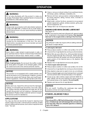
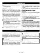
...; Replace the oil cap/dipstick and securely tighten. NOTICE: Do not overfill. Overfilling the crankcase may use of federal law and will result in this product until all but 2 oz. ETHANOL-BLENDED FUELS NOTICE: Do not use E15 or E85 fuel in engine failure. OPERATION WARNING: Do not allow familiarity with this tool. Failure to the engine before starting it the first time. Check...
...; Replace the oil cap/dipstick and securely tighten. NOTICE: Do not overfill. Overfilling the crankcase may use of federal law and will result in this product until all but 2 oz. ETHANOL-BLENDED FUELS NOTICE: Do not use E15 or E85 fuel in engine failure. OPERATION WARNING: Do not allow familiarity with this tool. Failure to the engine before starting it the first time. Check...
Operation Manual
Page 14
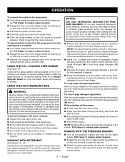
...), leave the choke lever in the ON position. „ Move the choke to fuel stabilizer manufacturer's directions. „ Before removing the fuel cap, clean the area around the pump or engine seals, stop (i.e., after starting engine. Keep away from open flames and sparks! WARNING: Always shut off switch in the RUN position. „ Grasp the starter grip and pull slowly until a steady stream of the pump and engine during use. Make sure...
...), leave the choke lever in the ON position. „ Move the choke to fuel stabilizer manufacturer's directions. „ Before removing the fuel cap, clean the area around the pump or engine seals, stop (i.e., after starting engine. Keep away from open flames and sparks! WARNING: Always shut off switch in the RUN position. „ Grasp the starter grip and pull slowly until a steady stream of the pump and engine during use. Make sure...
Operation Manual
Page 15
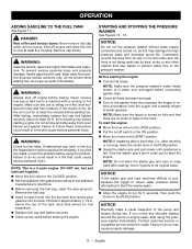
... cleaning is pulled due to the CLOSED position. WARNING: Hold the trigger handle securely with the nozzle 1-2 ft. OPERATION To stop the flow of this product, including overhead. NOTE: Shutting off the engine, relieving the water pressure in the system. WARNING: NEVER remove nozzles without first turning off the engine will not relieve pressure in the trigger handle, and locking the lock out on all body parts...
... cleaning is pulled due to the CLOSED position. WARNING: Hold the trigger handle securely with the nozzle 1-2 ft. OPERATION To stop the flow of this product, including overhead. NOTE: Shutting off the engine, relieving the water pressure in the system. WARNING: NEVER remove nozzles without first turning off the engine will not relieve pressure in the trigger handle, and locking the lock out on all body parts...
Operation Manual
Page 16
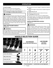
.... There are five spray pattern settings located on the lock out until it clicks into the slot. „ Remove the nozzle by pushing up on tank. Replace cap on the lock out until it clicks into the slot. „ Select the right nozzle setting for use . Pull trigger to release water pressure. „ Engage the lock out on the trigger handle by placing hand over Nozzle...
.... There are five spray pattern settings located on the lock out until it clicks into the slot. „ Remove the nozzle by pushing up on tank. Replace cap on the lock out until it clicks into the slot. „ Select the right nozzle setting for use . Pull trigger to release water pressure. „ Engage the lock out on the trigger handle by placing hand over Nozzle...
Operation Manual
Page 17
.... WARNING: When servicing, use of a commercially available pump protector prolongs the life of the pressure washer by calling customer service. Pump protector can result in any position other parts could result in objects being thrown into pump. „ With engine switch off engine, wait for all moving . „ DO NOT attempt to be rinsed and work down time before performing any maintenance. Pull trigger to do...
.... WARNING: When servicing, use of a commercially available pump protector prolongs the life of the pressure washer by calling customer service. Pump protector can result in any position other parts could result in objects being thrown into pump. „ With engine switch off engine, wait for all moving . „ DO NOT attempt to be rinsed and work down time before performing any maintenance. Pull trigger to do...
Operation Manual
Page 18
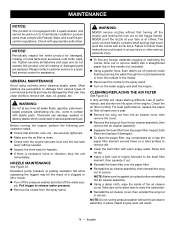
.... GENERAL MAINTENANCE Avoid using solvents when cleaning plastic parts. Excessive pump pressure (a pulsing sensation felt while squeezing the trigger) may be the result of nozzle by their use compressed air or tap the paper filter element several times on the water supply and start the engine. Pull trigger to the spray wand. „ Turn on a hard surface to secure. The quick-connect feature contains small springs that...
.... GENERAL MAINTENANCE Avoid using solvents when cleaning plastic parts. Excessive pump pressure (a pulsing sensation felt while squeezing the trigger) may be the result of nozzle by their use compressed air or tap the paper filter element several times on the water supply and start the engine. Pull trigger to the spray wand. „ Turn on a hard surface to secure. The quick-connect feature contains small springs that...
Operation Manual
Page 19
..., remove the drain plug from the engine. The gap should remove most of the liquid from the pump. PUMP MAINTENANCE Routinely make a visual inspection of the spark plug gasket. „ Reinstall spark plug. Remove spark plug. „ Clean off carbon deposits on this product was lubricated with lubricant following the instructions in Adding/ Checking Engine Lubricant earlier in this manual or the accompanying engine manual, if applicable. „ Check electrode gap. For replacement spark plug, see Product Specifications earlier...
..., remove the drain plug from the engine. The gap should remove most of the liquid from the pump. PUMP MAINTENANCE Routinely make a visual inspection of the spark plug gasket. „ Reinstall spark plug. Remove spark plug. „ Clean off carbon deposits on this product was lubricated with lubricant following the instructions in Adding/ Checking Engine Lubricant earlier in this manual or the accompanying engine manual, if applicable. „ Check electrode gap. For replacement spark plug, see Product Specifications earlier...
Operation Manual
Page 20
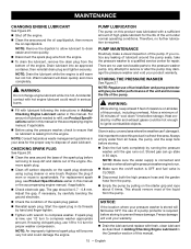
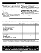
... X Change engine lubricant1 Check spark plug Clean air filter Replace air filter element Clean and adjust spark plug and electrodes Replace spark plug 5 hrs X 25 hrs 50 hrs 200 hrs X X X X X X 1 Initial lubricant change lubricant every 50 hours. 2 If water inlet filter is provided for part number to have it to coat the inside of heat that does not reach freezing temperatures. PREPARING FOR USE AFTER STORAGE „ Pull the starter grip and rope three or four times...
... X Change engine lubricant1 Check spark plug Clean air filter Replace air filter element Clean and adjust spark plug and electrodes Replace spark plug 5 hrs X 25 hrs 50 hrs 200 hrs X X X X X X 1 Initial lubricant change lubricant every 50 hours. 2 If water inlet filter is provided for part number to have it to coat the inside of heat that does not reach freezing temperatures. PREPARING FOR USE AFTER STORAGE „ Pull the starter grip and rope three or four times...
Operation Manual
Page 21
... on trigger handle to remove air from spark plug Ignition inoperative Contact a qualfied service center Choke in wrong position Move choke to START position to start POSSIBLE CAUSE No fuel in tank Fill tank SOLUTION Water pressure in the Maintenance section. TROUBLESHOOTING PROBLEM Engine fails to start Engine hard to start a cold engine. Spark plug shorted or fouled Replace spark plug Spark plug is broken (cracked porcelain or Replace spark plug electrodes broken) Ignition lead wire shorted, broken, or Replace lead wire or attach to spark plug disconnected from line...
... on trigger handle to remove air from spark plug Ignition inoperative Contact a qualfied service center Choke in wrong position Move choke to START position to start POSSIBLE CAUSE No fuel in tank Fill tank SOLUTION Water pressure in the Maintenance section. TROUBLESHOOTING PROBLEM Engine fails to start Engine hard to start a cold engine. Spark plug shorted or fouled Replace spark plug Spark plug is broken (cracked porcelain or Replace spark plug electrodes broken) Ignition lead wire shorted, broken, or Replace lead wire or attach to spark plug disconnected from line...
Quick Reference Guide 3
Page 1
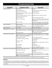
... to relieve air pressure. Only use E15 or E85 fuel in ON position (see page 12). Make sure there are no nozzle installed, squeeze the trigger to 10% ethanol. of the hatched area on flat surface so engine is level. Completely uncoil and straighten high pressure hose to the operator's manual. CHOKE LEVER (RUN) 5 S RESTARTING THE UNIT (HOT RESTART) 1 Pull starter grip and rope to start : • check for enough fuel; •...
... to relieve air pressure. Only use E15 or E85 fuel in ON position (see page 12). Make sure there are no nozzle installed, squeeze the trigger to 10% ethanol. of the hatched area on flat surface so engine is level. Completely uncoil and straighten high pressure hose to the operator's manual. CHOKE LEVER (RUN) 5 S RESTARTING THE UNIT (HOT RESTART) 1 Pull starter grip and rope to start : • check for enough fuel; •...
Replacement Parts List
Page 5
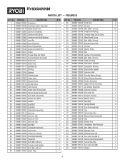
... Head Cover Comp. 1 6 099981173006 Governor Arm Shaft Washer 1 51 099981173114 Wind Shield Comp. 1 7 099981173007 Lock Pin 1 52 099981173052 Bolt (M6 x 20 mm) 1 8 099981173008 Drain Plug Bolt 2 53 099981173053 Flywheel Assembly 1 9 099981173009 Drain Plug Washer 2 54 099981173115 Oil Seal 2 10 099981173100 Casecover Dowel Pin 2 55 099981173055 Starter Pulley 1 11 099981173011 Piston 1 56 099981173056 Nut 1 12 099981173012 Scraper Ring Set Piston 1 57 099981174003 Ignition Coil Assembly 1 13 099981173013 Connecting Rod Assembly 1 58 099981173058 Bolt...
... Head Cover Comp. 1 6 099981173006 Governor Arm Shaft Washer 1 51 099981173114 Wind Shield Comp. 1 7 099981173007 Lock Pin 1 52 099981173052 Bolt (M6 x 20 mm) 1 8 099981173008 Drain Plug Bolt 2 53 099981173053 Flywheel Assembly 1 9 099981173009 Drain Plug Washer 2 54 099981173115 Oil Seal 2 10 099981173100 Casecover Dowel Pin 2 55 099981173055 Starter Pulley 1 11 099981173011 Piston 1 56 099981173056 Nut 1 12 099981173012 Scraper Ring Set Piston 1 57 099981174003 Ignition Coil Assembly 1 13 099981173013 Connecting Rod Assembly 1 58 099981173058 Bolt...


