
User Manual
Page 11
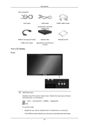
... Cable Network Box RGB to AV Cable (Applicable to the EX model only) Your LCD Display Front Wall Mount KIT SOURCE button Switches from PC mode to . [PC] → [AV] → [Component] → [HDMI] → [MagicInfo] Note For an EX model, • MagicInfo can only be enabled when a network box is connected...
... Cable Network Box RGB to AV Cable (Applicable to the EX model only) Your LCD Display Front Wall Mount KIT SOURCE button Switches from PC mode to . [PC] → [AV] → [Component] → [HDMI] → [MagicInfo] Note For an EX model, • MagicInfo can only be enabled when a network box is connected...

User Manual
Page 14
... the DVI IN port. RGB / COMPONENT / AV IN • Connect the [RGB/COMPONENT/AV IN] port of the product to the RGB port of the PC using the D-SUB cable. • Connect the [RGB / COMPONENT / AV IN] port on the monitor to the Component port on the external device using the... RGB to Component cable. • Connect the [RGB / COMPONENT / AV IN] port on the monitor to the BNC port on the PC using the RGB to BNC cable. • Connect the [RGB / COMPONENT / AV IN] port on the monitor to the AV port on the external device...
... the DVI IN port. RGB / COMPONENT / AV IN • Connect the [RGB/COMPONENT/AV IN] port of the product to the RGB port of the PC using the D-SUB cable. • Connect the [RGB / COMPONENT / AV IN] port on the monitor to the Component port on the external device using the... RGB to Component cable. • Connect the [RGB / COMPONENT / AV IN] port on the monitor to the BNC port on the PC using the RGB to BNC cable. • Connect the [RGB / COMPONENT / AV IN] port on the monitor to the AV port on the external device...
User Manual
Page 15
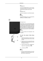
... AUDIO IN Connect the [AUDIO IN] port on the monitor to lock the product so that enables users to the audio output port on the PC or on the external device using an audio cable. Since the shape and usage of the Kensington lock cable. 3. Lock the lock ( ). For exact instructions...
... AUDIO IN Connect the [AUDIO IN] port on the monitor to lock the product so that enables users to the audio output port on the PC or on the external device using an audio cable. Since the shape and usage of the Kensington lock cable. 3. Lock the lock ( ). For exact instructions...

User Manual
Page 35
Choose one from the following options. Connections Connecting a Computer There are several ways to connect the computer to the 15-pin, [RGB / COMPONENT / AV IN] port on the back of your LCD Display and the 15 pin D-sub Port on the computer. Using the D-sub (Analog) connector on the PC using the HDMI cable. 34 Using the HDMI (digital) output on the graphics card. • Connect the [HDMI IN] port on the LCD Display to the HDMI port on the video card. • Connect the D-sub to the monitor.
Choose one from the following options. Connections Connecting a Computer There are several ways to connect the computer to the 15-pin, [RGB / COMPONENT / AV IN] port on the back of your LCD Display and the 15 pin D-sub Port on the computer. Using the D-sub (Analog) connector on the PC using the HDMI cable. 34 Using the HDMI (digital) output on the graphics card. • Connect the [HDMI IN] port on the LCD Display to the HDMI port on the video card. • Connect the D-sub to the monitor.
User Manual
Page 36
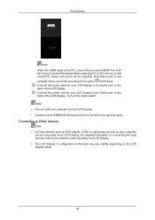
... Power port on the back of the LCD Display. Connections Note When the HDMI cable to the PC, ensure that you select HDMI from both your computer and the LCD Display. • Contact a local SAMSUNG Electronics Service Center to buy optional items. Connecting to Other devices Note • AV input devices such... on the back of the LCD Display. Note • Turn on the power switch. Turn on both the Source List and Edit Name before selecting PC or DVI device so that normal PC screen and sound can be outputted.
... Power port on the back of the LCD Display. Connections Note When the HDMI cable to the PC, ensure that you select HDMI from both your computer and the LCD Display. • Contact a local SAMSUNG Electronics Service Center to buy optional items. Connecting to Other devices Note • AV input devices such... on the back of the LCD Display. Note • Turn on the power switch. Turn on both the Source List and Edit Name before selecting PC or DVI device so that normal PC screen and sound can be outputted.

User Manual
Page 39
Connect the red and white jacks of an RCA to stereo (for PC) cable to the same colored audio output terminals of the digital output device, and connect the opposite jack to HDMI Cable 1. Select HDMI using a DVI ...
Connect the red and white jacks of an RCA to stereo (for PC) cable to the same colored audio output terminals of the digital output device, and connect the opposite jack to HDMI Cable 1. Select HDMI using a DVI ...
User Manual
Page 53
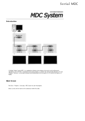
Introduction MDC A Multiple Display Control (MDC) is used for the communication between the serial port on a PC and the serial port on a PC. Main Screen Click Start > Program > Samsung > MDC System to be connected between a PC and a display. Select a set within the slider. Therefore, a serial cable should be easily and simultaneously operated on a display. RS-232C, a standard of the selected set to see the volume of serial communication, is an application allowing various displays to start the program.
Introduction MDC A Multiple Display Control (MDC) is used for the communication between the serial port on a PC and the serial port on a PC. Main Screen Click Start > Program > Samsung > MDC System to be connected between a PC and a display. Select a set within the slider. Therefore, a serial cable should be easily and simultaneously operated on a display. RS-232C, a standard of the selected set to see the volume of serial communication, is an application allowing various displays to start the program.

User Manual
Page 54
... the status at the time the MDC is shut down, the remote control signal receiving function of the monitors can change. This searches for the PC Serial Port can be supported depending on selected display. 13. The remote control Enable/Disable function operates whether or not the power is indicated in...
... the status at the time the MDC is shut down, the remote control signal receiving function of the monitors can change. This searches for the PC Serial Port can be supported depending on selected display. 13. The remote control Enable/Disable function operates whether or not the power is indicated in...

User Manual
Page 58
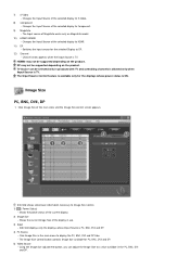
Changes the Input Source of the selected display to DTV. 6) AV - Changes the Input Source of the selected display to PC. 2) BNC - Changes the Input Source of the selected display to BNC. 3) DVI - Changes the Input Source of the selected display to DVI. 4) TV - Changes the Input Source of the selected display to TV. 5) DTV - • PC Mode Info Grid shows some basic information necessary to AV. Changes the Input Source of the selected display to Input Source Control. 1) PC -
Changes the Input Source of the selected display to DTV. 6) AV - Changes the Input Source of the selected display to PC. 2) BNC - Changes the Input Source of the selected display to BNC. 3) DVI - Changes the Input Source of the selected display to DVI. 4) TV - Changes the Input Source of the selected display to TV. 5) DTV - • PC Mode Info Grid shows some basic information necessary to AV. Changes the Input Source of the selected display to Input Source Control. 1) PC -
User Manual
Page 59
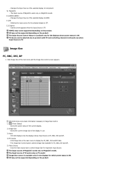
... - 7) S-Video - Changes the Input Source of the display in products with TV and controlling channels is allowed only when Input Source is PC, BNC, DVI and DP. 4) PC Source - Switches the input source for the selected Display to Image Size Control. 1) ( Power Status) - Channel arrow appears when the Input... HDMI2 may not be supported depending on MagicInfo model. 10) HDMI1/HDMI2 - Click Image Size in the PC, BNC, DVI and DP. The Input Source Control feature is available only for PC, BNC, DVI and DP. 5) Video Source - DP may not be supported depending on the product. ...
... - 7) S-Video - Changes the Input Source of the display in products with TV and controlling channels is allowed only when Input Source is PC, BNC, DVI and DP. 4) PC Source - Switches the input source for the selected Display to Image Size Control. 1) ( Power Status) - Channel arrow appears when the Input... HDMI2 may not be supported depending on MagicInfo model. 10) HDMI1/HDMI2 - Click Image Size in the PC, BNC, DVI and DP. The Input Source Control feature is available only for PC, BNC, DVI and DP. 5) Video Source - DP may not be supported depending on the product. ...
User Manual
Page 61
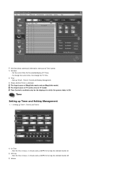
... the selected monitor on. 2) Off Time - The Input source of MagicInfo works only on TV model. To change the current time, first change the PC Time. 2) Timer - Sets the time in hours, in minutes and as AM/PM for turning the selected monitor off. 3) Volume Set the current... time for which the power status is activated. Time Control is available only for the displays for the selected display (PC Time). - Time Setting up Timer1, Timer2 and Timer3 1) On Time - Setting up Timer and Holiday Management 1. 1. Sets up Timer1, Timer2, Timer3 and Holiday ...
... the selected monitor on. 2) Off Time - The Input source of MagicInfo works only on TV model. To change the current time, first change the PC Time. 2) Timer - Sets the time in hours, in minutes and as AM/PM for turning the selected monitor off. 3) Volume Set the current... time for which the power status is activated. Time Control is available only for the displays for the selected display (PC Time). - Time Setting up Timer1, Timer2 and Timer3 1) On Time - Setting up Timer and Holiday Management 1. 1. Sets up Timer1, Timer2, Timer3 and Holiday ...

User Manual
Page 64
.... 9) Component - Changes the source of the PIP of the selected display to AV. 8) S-Video - Changes the source of the PIP of the selected display to PC. 3) BNC - Click Settings of the selected display to DVI. 5) TV - Changes the source of the PIP of the main icons and the Settings Control screen... the source of the PIP of the selected display to HDMI. 11) DP - The Input source of MagicInfo works only on the LCD Display power. 2) PC -
.... 9) Component - Changes the source of the PIP of the selected display to AV. 8) S-Video - Changes the source of the PIP of the selected display to PC. 3) BNC - Click Settings of the selected display to DVI. 5) TV - Changes the source of the PIP of the main icons and the Settings Control screen... the source of the PIP of the selected display to HDMI. 11) DP - The Input source of MagicInfo works only on the LCD Display power. 2) PC -
User Manual
Page 65
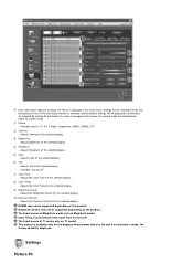
... Brightness of the selected display. - Adjusts Tint of the selected display. 4) Sharpness - Adjusts the Color Tone for the selected display. 10) Dynamic Contrast - Settings Picture PC This feature is available only for TV, AV, S-Video, Component, HDMI1, HDMI2, DTV. 2) Contrast - Brightness Sensor may not be displayed if one of TV works...
... Brightness of the selected display. - Adjusts Tint of the selected display. 4) Sharpness - Adjusts the Color Tone for the selected display. 10) Dynamic Contrast - Settings Picture PC This feature is available only for TV, AV, S-Video, Component, HDMI1, HDMI2, DTV. 2) Contrast - Brightness Sensor may not be displayed if one of TV works...
User Manual
Page 66
...will be imported and displayed on the slider if a display ID is selected, and the default settings will automatically switch to custom mode. 1) Picture PC - If a value is displayed. Available only for the selected display. 8) Color Temp - Adjusts blue Color of the selected display. - Adjusts... the Color Tone for NT. 5) Green - Adjusts the Brightness Sensor for PC, BNC, DVI and DP. 2) Contrast - Available only for the selected display. 10) Dynamic Contrast - The Input source of TV works only on MagicInfo...
...will be imported and displayed on the slider if a display ID is selected, and the default settings will automatically switch to custom mode. 1) Picture PC - If a value is displayed. Available only for the selected display. 8) Color Temp - Adjusts blue Color of the selected display. - Adjusts... the Color Tone for NT. 5) Green - Adjusts the Brightness Sensor for PC, BNC, DVI and DP. 2) Contrast - Available only for the selected display. 10) Dynamic Contrast - The Input source of TV works only on MagicInfo...

User Manual
Page 68
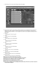
...display. 3) Fine - Adjusts Coarse of the selected display. 4) Position - Click on the "Maintenance" icon in the Main Icon column to the incoming PC signal. Maintenance Lamp Control 1. Adjusts Position of TV works only on MagicInfo model. Self-Adjust to display the Maintenance screen. Available only for which the... power status is available only for the displays for PC, BNC. 2) Coarse - Settings Control is ON. Info Grid shows some basic information necessary to Settings Control. 1) Image Lock -
...display. 3) Fine - Adjusts Coarse of the selected display. 4) Position - Click on the "Maintenance" icon in the Main Icon column to the incoming PC signal. Maintenance Lamp Control 1. Adjusts Position of TV works only on MagicInfo model. Self-Adjust to display the Maintenance screen. Available only for which the... power status is available only for the displays for PC, BNC. 2) Coarse - Settings Control is ON. Info Grid shows some basic information necessary to Settings Control. 1) Image Lock -

User Manual
Page 74
Main Screen Click Start > Program > Samsung > MDC System to see the volume of the selected set to start the program. Select a set within the slider. Refer to another display device, use an RS-232C serial cable. Connect the first display device and the PC by entering the IP address. To connect to the figure above. Introduction Ehternet MDC Unlike the previous method which used the serial data communication specifications RS-232C, an Ethernet function has been added.
Main Screen Click Start > Program > Samsung > MDC System to see the volume of the selected set to start the program. Select a set within the slider. Refer to another display device, use an RS-232C serial cable. Connect the first display device and the PC by entering the IP address. To connect to the figure above. Introduction Ehternet MDC Unlike the previous method which used the serial data communication specifications RS-232C, an Ethernet function has been added.

User Manual
Page 79
Changes the Input Source of the selected display to BNC. 3) DVI - Changes the Input Source of the selected display to S-Video. 8) Component Changes the Input Source of the selected display to PC. 2) BNC - Changes the Input Source of the selected display to Input Source Control. 1) PC - • PC Mode Info Grid shows some basic information necessary to DVI. 4) TV - Changes the Input Source of the selected display to AV. 7) S-Video - Changes the Input Source of the selected display to DTV. 6) AV - Changes the Input Source of the selected display to TV. 5) DTV -
Changes the Input Source of the selected display to BNC. 3) DVI - Changes the Input Source of the selected display to S-Video. 8) Component Changes the Input Source of the selected display to PC. 2) BNC - Changes the Input Source of the selected display to Input Source Control. 1) PC - • PC Mode Info Grid shows some basic information necessary to DVI. 4) TV - Changes the Input Source of the selected display to AV. 7) S-Video - Changes the Input Source of the selected display to DTV. 6) AV - Changes the Input Source of the selected display to TV. 5) DTV -
User Manual
Page 80
... power status is ON. DP may not be supported depending on the product. Click Image Size of the selected display to control Image Size for PC, BNC, DVI and DP. 5) Video Source - Click the Video Source tab to HDMI. 11) DP - Changes the Input Source of the main icons and...Source of the current display. 2) Image Size - Info Grid shows some basic information necessary to display the PC, BNC, DVI and DP tabs. - Switches the input source for which power status is ON. Image Size PC, BNC, DVI, DP 1. Shows the power status of the selected display to DP. 12) Channel -...
... power status is ON. DP may not be supported depending on the product. Click Image Size of the selected display to control Image Size for PC, BNC, DVI and DP. 5) Video Source - Click the Video Source tab to HDMI. 11) DP - Changes the Input Source of the main icons and...Source of the current display. 2) Image Size - Info Grid shows some basic information necessary to display the PC, BNC, DVI and DP tabs. - Switches the input source for which power status is ON. Image Size PC, BNC, DVI, DP 1. Shows the power status of the selected display to DP. 12) Channel -...

User Manual
Page 82
...- Sets up Timer1, Timer2, Timer3 and Holiday Management. 3) Shows whether Timer is ON. Time Control is available only for the displays for the selected display (PC Time). - Selects the volume when the selected monitor is turned on TV model. The Input source of TV works only on . Sets the time in... the external input source that will be displayed when the selected monitor is turned on MagicInfo model. To change the current time, first change the PC Time. 2) Timer - Set the current time for which the power status is activated. Sets the time in hours, in minutes and as AM/PM ...
...- Sets up Timer1, Timer2, Timer3 and Holiday Management. 3) Shows whether Timer is ON. Time Control is available only for the displays for the selected display (PC Time). - Selects the volume when the selected monitor is turned on TV model. The Input source of TV works only on . Sets the time in... the external input source that will be displayed when the selected monitor is turned on MagicInfo model. To change the current time, first change the PC Time. 2) Timer - Set the current time for which the power status is activated. Sets the time in hours, in minutes and as AM/PM ...

User Manual
Page 85
... source of the selected display to ON. Changes the source of the PIP of MagicInfo works only on the LCD Display power. 2) PC - The PIP Control feature is set to PC. 3) BNC - Changes the source of the PIP of the selected Display to BNC. 4) DVI - Switches the PIP Source of the selected...
... source of the selected display to ON. Changes the source of the PIP of MagicInfo works only on the LCD Display power. 2) PC - The PIP Control feature is set to PC. 3) BNC - Changes the source of the PIP of the selected Display to BNC. 4) DVI - Switches the PIP Source of the selected...

