
Service Manual
Page 1
Operating Instructions 4. Exploded Views and Parts List 8. Precaution 2. Schematic Diagrams Troubleshooting 7. Disassembly and Reassembly 5. Specifications 3. PCB Diagrams 9. MICROWAVE OVEN MW5580W SERVICE Manual MICROWAVE OVEN SECA One Minute + Popcorn Frozen Dinner Fresh Vegetable Diet Cook Potato Frozen Breakfast Auto Defrost Auto Reheat 12 45 78 Power Level 0 3 6 9 More/Less Clock Auto Start Pause Cancel Hold Timer Start MW5580W CONTENTS 1. Alignment and Adjustments 6.
Operating Instructions 4. Exploded Views and Parts List 8. Precaution 2. Schematic Diagrams Troubleshooting 7. Disassembly and Reassembly 5. Specifications 3. PCB Diagrams 9. MICROWAVE OVEN MW5580W SERVICE Manual MICROWAVE OVEN SECA One Minute + Popcorn Frozen Dinner Fresh Vegetable Diet Cook Potato Frozen Breakfast Auto Defrost Auto Reheat 12 45 78 Power Level 0 3 6 9 More/Less Clock Auto Start Pause Cancel Hold Timer Start MW5580W CONTENTS 1. Alignment and Adjustments 6.

Service Manual
Page 2
... hinges and latches, (5) evidence of dropping or abuse. (c) Before turning on microwave power for any service test or inspection within the microwave generating compartments, check the magnetron, wave guide or transmission line, and cavity for proper alignment, integrity, and connections. (d) Any defective or misadjusted components in the interlock, monitor, door seal, and microwave generation and transmission systems shall be repaired, replaced, or adjusted...
... hinges and latches, (5) evidence of dropping or abuse. (c) Before turning on microwave power for any service test or inspection within the microwave generating compartments, check the magnetron, wave guide or transmission line, and cavity for proper alignment, integrity, and connections. (d) Any defective or misadjusted components in the interlock, monitor, door seal, and microwave generation and transmission systems shall be repaired, replaced, or adjusted...

Service Manual
Page 3
... cabinet openings through which people--particularly children--might insert objects and contact dangerous voltages. Any design changes or additions will void the manufacturer's warranty.10.Always unplug the unit's AC power cord from your body by touching a known earth ground. 16. Samsung Electronics 1-1 Instruct owner not to servicing if the oven is operative. 3. Never defeat any missing protective shields. 7. Such components are correctly installed...
... cabinet openings through which people--particularly children--might insert objects and contact dangerous voltages. Any design changes or additions will void the manufacturer's warranty.10.Always unplug the unit's AC power cord from your body by touching a known earth ground. 16. Samsung Electronics 1-1 Instruct owner not to servicing if the oven is operative. 3. Never defeat any missing protective shields. 7. Such components are correctly installed...
Service Manual
Page 4
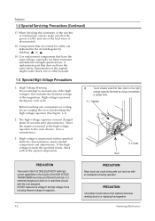
... or replacing the magnetron. Before touching any of the high voltages--this includes the filament voltage of the HIGH VOTAGE TRANSFORMER secondary and filament terminals. PRECAUTION Servicemen should remove their watches whenever working close -tolerance, safety-related components and adjustments. Samsung Electronics Diode Short PRECAUTION There exists HIGH VOLTAGE ELECTRICITY with high current capabilities in the circuit diagram by using...
... or replacing the magnetron. Before touching any of the high voltages--this includes the filament voltage of the HIGH VOTAGE TRANSFORMER secondary and filament terminals. PRECAUTION Servicemen should remove their watches whenever working close -tolerance, safety-related components and adjustments. Samsung Electronics Diode Short PRECAUTION There exists HIGH VOLTAGE ELECTRICITY with high current capabilities in the circuit diagram by using...

Service Manual
Page 5
Specifications 2-1 Table of Specifications ITEM TIMER POWER SOURCE POWER CONSUMPTION OUTPUT POWER MODEL OPERATING FREQUENCY MAGNETRON COOLING METHOD OUTSIDE DIMENSIONS NET WEIGHT SHIPPING WEIGHT 2-2 Comparison Chart FEATURE MORE/LESS AUTO REHEAT AUTO DEFROST TIME COOK POWER LEVEL INSTANT COOK MEMORY CHILD LOCK LOCK/AUTO START SOUND DEMO MODE HELP SCREEN MODEL MW5580W 99 MINUTES 99 SECONDS 120V/60HZ, AC MICROWAVE : 1,500W FROM 100W TO 1000W (IEC-705 TEST PROCEDURE) 2,450MHz OM75P COOLING FAN MOTOR 2117/32"(W) x 127/8"(H) x 157/16"(D 41.2 LBS. 43.0 LBS. MW5580W O O O O O (6EA) O O O ...
Specifications 2-1 Table of Specifications ITEM TIMER POWER SOURCE POWER CONSUMPTION OUTPUT POWER MODEL OPERATING FREQUENCY MAGNETRON COOLING METHOD OUTSIDE DIMENSIONS NET WEIGHT SHIPPING WEIGHT 2-2 Comparison Chart FEATURE MORE/LESS AUTO REHEAT AUTO DEFROST TIME COOK POWER LEVEL INSTANT COOK MEMORY CHILD LOCK LOCK/AUTO START SOUND DEMO MODE HELP SCREEN MODEL MW5580W 99 MINUTES 99 SECONDS 120V/60HZ, AC MICROWAVE : 1,500W FROM 100W TO 1000W (IEC-705 TEST PROCEDURE) 2,450MHz OM75P COOLING FAN MOTOR 2117/32"(W) x 127/8"(H) x 157/16"(D 41.2 LBS. 43.0 LBS. MW5580W O O O O O (6EA) O O O ...

Service Manual
Page 6
POWER LEVLE Press to set the heating level. Door Ventilation Holes Light Safety Interlock Holes Door Latches Glass Tray Guide Roller One Minute + Popcorn Frozen Dinner Fresh Vegetable Diet Cook Potato Frozen Breakfast Auto Defrost Auto Reheat 12 45 78 Power Level 0 3 6 9 More/Less Clock Auto Start Pause Cancel Hold Timer Start MW5580W Control Panel Open Door Push Button 313mm 402mm 556mm Samsung Electronics 260mm 429mm 3-1 twice to cancel. 3-2 Features & External Views One Minute + Popcorn Frozen Dinner Fresh Vegetable Diet Cook Potato Frozen...
POWER LEVLE Press to set the heating level. Door Ventilation Holes Light Safety Interlock Holes Door Latches Glass Tray Guide Roller One Minute + Popcorn Frozen Dinner Fresh Vegetable Diet Cook Potato Frozen Breakfast Auto Defrost Auto Reheat 12 45 78 Power Level 0 3 6 9 More/Less Clock Auto Start Pause Cancel Hold Timer Start MW5580W Control Panel Open Door Push Button 313mm 402mm 556mm Samsung Electronics 260mm 429mm 3-1 twice to cancel. 3-2 Features & External Views One Minute + Popcorn Frozen Dinner Fresh Vegetable Diet Cook Potato Frozen...
Service Manual
Page 7
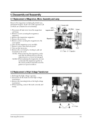
... antenna does not hit any adjacent parts, or it may be sure to the wave guide. 6. When replacing, connect the leads correctly and firmly. Remove the oven lamp by rotating to pull out from the back panel. 8. Trans 4-1 NOTE2: When replacing the magnetron, be damaged. Disconnect all lead wires from the high voltage transformer. 3. Remove a screw securing the magnetron supporter. 3. Trans H. Take out the fan motor. 9. Samsung Electronics H.
... antenna does not hit any adjacent parts, or it may be sure to the wave guide. 6. When replacing, connect the leads correctly and firmly. Remove the oven lamp by rotating to pull out from the back panel. 8. Trans 4-1 NOTE2: When replacing the magnetron, be damaged. Disconnect all lead wires from the high voltage transformer. 3. Remove a screw securing the magnetron supporter. 3. Trans H. Take out the fan motor. 9. Samsung Electronics H.

Service Manual
Page 8
... 4-3-2 Removal of Door Screen Film 1. Be careful when handling Door "C" which is impossible,replace with Assembly door "E". 4-3-4 Removal of Door Assembly Remove hex bolts securing the upper hinge and lower hinge. Detach spring from Door "A" and key door. 4-2 Lower Hinge Protect Tape Flat Screw Driver Door "C" Door "E " Flat Screw Driver Door "C " Door "E" Door "A " Key Door Hook to hang the key spring Spring Door "E" Push door key in this direction to remove Door "C". Samsung Electronics Push key door upward and remove it out. Use...
... 4-3-2 Removal of Door Screen Film 1. Be careful when handling Door "C" which is impossible,replace with Assembly door "E". 4-3-4 Removal of Door Assembly Remove hex bolts securing the upper hinge and lower hinge. Detach spring from Door "A" and key door. 4-2 Lower Hinge Protect Tape Flat Screw Driver Door "C" Door "E " Flat Screw Driver Door "C " Door "E" Door "A " Key Door Hook to hang the key spring Spring Door "E" Push door key in this direction to remove Door "C". Samsung Electronics Push key door upward and remove it out. Use...
Service Manual
Page 9
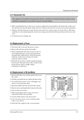
If the door assembly is defective. 4-5 Replacement of Fuse 1. Remove the 20A fuse in the correct poaition. Take out the glass tray and the guide roller from the space between the inner door surface and oven front surface. Take out the drive motor. 7. Screw the drive motor cover to use an exact replacement part. When the above three switches operate properly, check if any other part such as to the bottom line...
If the door assembly is defective. 4-5 Replacement of Fuse 1. Remove the 20A fuse in the correct poaition. Take out the glass tray and the guide roller from the space between the inner door surface and oven front surface. Take out the drive motor. 7. Screw the drive motor cover to use an exact replacement part. When the above three switches operate properly, check if any other part such as to the bottom line...

Service Manual
Page 10
... never touch the control circuitry. 2. When installing new membrane key board, make sure that the surface of hair dryer is difficult, replace with mounting tabs location. 2. Window display should not be disassembled as using of escutcheon base is attached to prevent any static electric charge in accordance with Ass'y control panel assembly. 5. Disassembly and Reassembly 4-6 Replacement of Control Circuit Board 4-6-1 Removal of membrane panel. 2. Remove screws securing the control circuit board...
... never touch the control circuitry. 2. When installing new membrane key board, make sure that the surface of hair dryer is difficult, replace with mounting tabs location. 2. Window display should not be disassembled as using of escutcheon base is attached to prevent any static electric charge in accordance with Ass'y control panel assembly. 5. Disassembly and Reassembly 4-6 Replacement of Control Circuit Board 4-6-1 Removal of membrane panel. 2. Remove screws securing the control circuit board...
Service Manual
Page 11
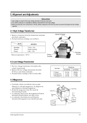
... oven from the circuit by disconnecting its power source and discharge the high voltage capacitor. 5-1 High Voltage Transformer 1. Continuity checks can indicate only an open filament or shorted magnetron : 2. To diagnose an open filament or a shorted magnetron. High voltage is located on the control circuit board. 2. Alignment and Adjustments PRECAUTION 1. A continuity check across the magnetron filament terminals should read open. 5. Before touching any cook...
... oven from the circuit by disconnecting its power source and discharge the high voltage capacitor. 5-1 High Voltage Transformer 1. Continuity checks can indicate only an open filament or shorted magnetron : 2. To diagnose an open filament or a shorted magnetron. High voltage is located on the control circuit board. 2. Alignment and Adjustments PRECAUTION 1. A continuity check across the magnetron filament terminals should read open. 5. Before touching any cook...
Service Manual
Page 12
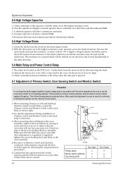
.... 2. No specific adjustment during installation of arrow in the other direction. 5-6 Main Relay and Power Control Relay 1. An open capacitor will not have any play in the oven. With the ohm-meter set to back resistance of the monitor circuit and all interlock switches and the interlock monitor switch. 1. Then follow the adjustment procedures below. Operate the microwave oven with the meter set at the...
.... 2. No specific adjustment during installation of arrow in the other direction. 5-6 Main Relay and Power Control Relay 1. An open capacitor will not have any play in the oven. With the ohm-meter set to back resistance of the monitor circuit and all interlock switches and the interlock monitor switch. 1. Then follow the adjustment procedures below. Operate the microwave oven with the meter set at the...

Service Manual
Page 13
... in the oven: 1. Microwave heat distribution rate can be calculated as follows: Heat Distribution = The result should be taken to the first place of each beaker. 6. Set the oven to 11ûC at certain positions in figure below. Minimum Temperature Rise Maximum Temperature Rise X 100(%) D Beaker D D/4 D/4 D/4 D/4 Cooking Tray Samsung Electronics 5-3 The output power is 9ûC to high power and operate for 2 minutes...
... in the oven: 1. Microwave heat distribution rate can be calculated as follows: Heat Distribution = The result should be taken to the first place of each beaker. 6. Set the oven to 11ûC at certain positions in figure below. Minimum Temperature Rise Maximum Temperature Rise X 100(%) D Beaker D D/4 D/4 D/4 D/4 Cooking Tray Samsung Electronics 5-3 The output power is 9ûC to high power and operate for 2 minutes...

Service Manual
Page 14
...; Remove the outer panel. 2. Place the spacer cone of the probe on the grip of the handle, otherwise a false reading may result. 5) Measured leakage must be held on the door and/or cabinet door seam and move the probe horizontally along the seam, the door viewing window and the exhaust openings SAMSUNG moving the probe in a clockwise direction at the highest power level...
...; Remove the outer panel. 2. Place the spacer cone of the probe on the grip of the handle, otherwise a false reading may result. 5) Measured leakage must be held on the door and/or cabinet door seam and move the probe horizontally along the seam, the door viewing window and the exhaust openings SAMSUNG moving the probe in a clockwise direction at the highest power level...
Service Manual
Page 15
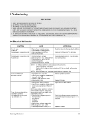
... power relay or Ass'y PCB Adjust door and latch switches. DISCHARGE THE HIGH VOLTAGE CAPACITOR. 4. ALWAYS TOUCH GROUND WHILE WORKING ON IT TO DISCHARGE ANY STATIC CHARGE BUILT UP. 6-1 Electrical Malfunction SYMPTOM CAUSE CORRECTIONS Oven is replaced, check diode and magnetron also. Shorted lead wire harness 2. Shorted HVTransformer (NOTE2) Check adjustment of latch switches 2. Key input is blown. 1. Timer starts countdown but no operation at all . Open thermal cutout (Magnetron) 3. Fuse...
... power relay or Ass'y PCB Adjust door and latch switches. DISCHARGE THE HIGH VOLTAGE CAPACITOR. 4. ALWAYS TOUCH GROUND WHILE WORKING ON IT TO DISCHARGE ANY STATIC CHARGE BUILT UP. 6-1 Electrical Malfunction SYMPTOM CAUSE CORRECTIONS Oven is replaced, check diode and magnetron also. Shorted lead wire harness 2. Shorted HVTransformer (NOTE2) Check adjustment of latch switches 2. Key input is blown. 1. Timer starts countdown but no operation at all . Open thermal cutout (Magnetron) 3. Fuse...

Service Manual
Page 16
... Oven lamp and fan motor turn on the oven wall. 2. Oven takes longer time to operate. Defective primary latch switch 1. Metallic ware or cooking dishes touching on Oven can be heard. Noise from the motor. Adjust door and interlock switches. Tighten screws of primary latch switch 2. Replace turntable motor. Misadjustment or loose wiring of H.V.Transformer. Defective secondary interlock S/W 1. Decrease in mode. Loose screws on when plugged in Oven does not operate and return to its characteristics. Open or loose wiring of microwave...
... Oven lamp and fan motor turn on the oven wall. 2. Oven takes longer time to operate. Defective primary latch switch 1. Metallic ware or cooking dishes touching on Oven can be heard. Noise from the motor. Adjust door and interlock switches. Tighten screws of primary latch switch 2. Replace turntable motor. Misadjustment or loose wiring of H.V.Transformer. Defective secondary interlock S/W 1. Decrease in mode. Loose screws on when plugged in Oven does not operate and return to its characteristics. Open or loose wiring of microwave...
Service Manual
Page 18
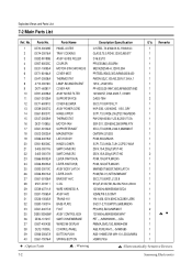
... 40 DE61-70076A : Option Parts Parts Name PANEL-OUTER TRAY-COOKING ASSY-GUIDE ROLLER COUPLER MOTOR-SYNCHRONOUS COVER-MGT THERMOSTAT LAMP-INCANDESCENT COVER-AIR ASSY NOISE FILTER SUPPORTER-PCB COVER-BLOWER ASSY POWER CORD HINGE-UPPER THERMOSTAT MOTOR-FAN SUPPORTER-MGT MAGNETRON LATCH-BODY HINGE-LOWER SWITCH-MICRO SWITCH-MICRO LEVER-SWITCH(A) LEVER-SWITCH(B) ASSY BODY LATCH LEVER-DOOR BRACKET-HVC C-OIL WIRE HARNESS-A ASSY-HVD TRANS-H.V BASE-PLATE FOOT ASSY CONTROL-BOX SWITCH-MEMBRANE WINDOW-DISPLAY CONTROL-PANEL BUTTON-PUSH SPRING-BUTTON Description/Specification C/STEEL,T0.6,W405.5,L1180...
... 40 DE61-70076A : Option Parts Parts Name PANEL-OUTER TRAY-COOKING ASSY-GUIDE ROLLER COUPLER MOTOR-SYNCHRONOUS COVER-MGT THERMOSTAT LAMP-INCANDESCENT COVER-AIR ASSY NOISE FILTER SUPPORTER-PCB COVER-BLOWER ASSY POWER CORD HINGE-UPPER THERMOSTAT MOTOR-FAN SUPPORTER-MGT MAGNETRON LATCH-BODY HINGE-LOWER SWITCH-MICRO SWITCH-MICRO LEVER-SWITCH(A) LEVER-SWITCH(B) ASSY BODY LATCH LEVER-DOOR BRACKET-HVC C-OIL WIRE HARNESS-A ASSY-HVD TRANS-H.V BASE-PLATE FOOT ASSY CONTROL-BOX SWITCH-MEMBRANE WINDOW-DISPLAY CONTROL-PANEL BUTTON-PUSH SPRING-BUTTON Description/Specification C/STEEL,T0.6,W405.5,L1180...

Service Manual
Page 19
... 51 DE64-40092A 52 DE63-90035G 53 DE02-00034A 54 DE93-30207B Parts Name HOLDER-DIGITRON ASSY PCB-MAIN ASSY DOOR DOOR-A SCREEN-DOOR-A ASSY DOOR-E SPRING-KEY PIN-HINGE DOOR-KEY DOOR-C DOOR-FILM CUSHION-RUBBER TAPE-DOUBLE FACE ASSY CONTROL-PANEL Description/Specification NYLON#66,T1.8,BLK,MW4370W 120V/60HZ,NS,V.F.D,N/HELP-SCRE MW6442W,WHT ...MW6730W PE-FILM,T0.15,W174,L305,MW6630 DFA20,T2,W190,L100,BLK ACRYL,T0.26,W20,WHT,3M-A-25-92 120V60Hz,MW5580W,PURE WHT Q'ty Remarks 1 1 1 1 1 1 1 2 1 1 1 1 1 1 Samsung Electronics 7-3 No. 7-2 Main Parts List Exploded Views and Parts List Ref.
... 51 DE64-40092A 52 DE63-90035G 53 DE02-00034A 54 DE93-30207B Parts Name HOLDER-DIGITRON ASSY PCB-MAIN ASSY DOOR DOOR-A SCREEN-DOOR-A ASSY DOOR-E SPRING-KEY PIN-HINGE DOOR-KEY DOOR-C DOOR-FILM CUSHION-RUBBER TAPE-DOUBLE FACE ASSY CONTROL-PANEL Description/Specification NYLON#66,T1.8,BLK,MW4370W 120V/60HZ,NS,V.F.D,N/HELP-SCRE MW6442W,WHT ...MW6730W PE-FILM,T0.15,W174,L305,MW6630 DFA20,T2,W190,L100,BLK ACRYL,T0.26,W20,WHT,3M-A-25-92 120V60Hz,MW5580W,PURE WHT Q'ty Remarks 1 1 1 1 1 1 1 2 1 1 1 1 1 1 Samsung Electronics 7-3 No. 7-2 Main Parts List Exploded Views and Parts List Ref.

Service Manual
Page 20
...DE60-20014A DE60-20014A DE60-30016A DE60-10012A Parts Name SCREW-TAP PH SCREW-TAP PH SCREW-TAP PH SCREW-TAP TH SCREW-WASHER SCREW-WASHER SCREW-A SCREW-A SCREW-A SCREW-A SCREW-A SCREW-A SCREW-A SCREW-A SCREW-A SCREW-TAPPING SCREW-TAP TH SCREW-TAP TH BOLT-FLANGE BOLT-FLANGE NUT-FLANGE SCREW-TAP TITE Description / Specification PH,M3,L6,FEFZY PH,M4,L8,...MG-TCO 2 HL/FUS 2 M/GEAR 1 B/HI-U 4 HVT 4 MGT 2 BD-LAT 2 C-CLAM 2 CN-PNL 1 CV/AIR 1 MEM-PN 1 P-CORD 5 PN/OUT 2 SU-PCB 1 SU/MGT 1 B/HVC 4 B-PLTE 5 P/FRNT 2 HI-LOW 2 HI-UPP 2 MO/FAN 7-6 Samsung Electronics
...DE60-20014A DE60-20014A DE60-30016A DE60-10012A Parts Name SCREW-TAP PH SCREW-TAP PH SCREW-TAP PH SCREW-TAP TH SCREW-WASHER SCREW-WASHER SCREW-A SCREW-A SCREW-A SCREW-A SCREW-A SCREW-A SCREW-A SCREW-A SCREW-A SCREW-TAPPING SCREW-TAP TH SCREW-TAP TH BOLT-FLANGE BOLT-FLANGE NUT-FLANGE SCREW-TAP TITE Description / Specification PH,M3,L6,FEFZY PH,M4,L8,...MG-TCO 2 HL/FUS 2 M/GEAR 1 B/HI-U 4 HVT 4 MGT 2 BD-LAT 2 C-CLAM 2 CN-PNL 1 CV/AIR 1 MEM-PN 1 P-CORD 5 PN/OUT 2 SU-PCB 1 SU/MGT 1 B/HVC 4 B-PLTE 5 P/FRNT 2 HI-LOW 2 HI-UPP 2 MO/FAN 7-6 Samsung Electronics

Service Manual
Page 23
.... DOOR : OPEN 3. Schematic Diagrams 9-1 Schematic Diagrams WARNING POWER MUST BE DISCONNECTED BEFORE SERVICING THIS APPLINACE CAVITY FUSE BLK TCO 250V20A WHT BLK LAMP PRIMARY S/W BLK BLK L 130V 40W BLK BLK ORG H. INPUT : 120V 60HZ 2. TRANSFORMER BLK 120V D/MOTOR MONITOR SWITCH FAN MOTOR VARISTOR L.V.TRANS MAIN RELAY L POWER CORD AC 120V/60Hz N 120V YEL COM FM DM 21V 0V NC NO YEL H. 9. V. NOTE: FOR SERVICE REPLACEMENT USE 16GA 105 C THERMOPLASTIC COVERED WIRE...
.... DOOR : OPEN 3. Schematic Diagrams 9-1 Schematic Diagrams WARNING POWER MUST BE DISCONNECTED BEFORE SERVICING THIS APPLINACE CAVITY FUSE BLK TCO 250V20A WHT BLK LAMP PRIMARY S/W BLK BLK L 130V 40W BLK BLK ORG H. INPUT : 120V 60HZ 2. TRANSFORMER BLK 120V D/MOTOR MONITOR SWITCH FAN MOTOR VARISTOR L.V.TRANS MAIN RELAY L POWER CORD AC 120V/60Hz N 120V YEL COM FM DM 21V 0V NC NO YEL H. 9. V. NOTE: FOR SERVICE REPLACEMENT USE 16GA 105 C THERMOPLASTIC COVERED WIRE...


