
Product Manual
Page 7
This interface allows a host computer to issue commands to the memory card to enhance system performance. Each sector is electrically compatible with an IDE disk drive. CompactFlash Memory cards use in a PCMCIA Type II or Type III socket. Once the card has been configured by SanDisk specifically for use SanDisk Flash memory, which was designed by the host, it appears to the host as a standard ATA (IDE...
This interface allows a host computer to issue commands to the memory card to enhance system performance. Each sector is electrically compatible with an IDE disk drive. CompactFlash Memory cards use in a PCMCIA Type II or Type III socket. Once the card has been configured by SanDisk specifically for use SanDisk Flash memory, which was designed by the host, it appears to the host as a standard ATA (IDE...

Product Manual
Page 9
SanDisk CompactFlash Card OEM Product Manual Introduction 1.5 PCMCIA Standard SanDisk CompactFlash Memory cards are fully electrically compatible with the PCMCIA specifications listed below: • PCMCIA PC Card Standard, 7.0, February 1999 • PCMCIA PC Card ATA Specification, 7.0, February 1999 These specifications may be ordered from IHS by ANSI. Documentation can be obtained from details of erasing and programming flash memory. • Sophisticated system for managing defects (analogous to systems...
SanDisk CompactFlash Card OEM Product Manual Introduction 1.5 PCMCIA Standard SanDisk CompactFlash Memory cards are fully electrically compatible with the PCMCIA specifications listed below: • PCMCIA PC Card Standard, 7.0, February 1999 • PCMCIA PC Card ATA Specification, 7.0, February 1999 These specifications may be ordered from IHS by ANSI. Documentation can be obtained from details of erasing and programming flash memory. • Sophisticated system for managing defects (analogous to systems...

Product Manual
Page 10
... intrinsic part of the erase pooling functionality of SanDisk CompactFlash using hardware on-the-fly Error Detection Code/Error Correction Code (EDC/ECC), based on -board controller, the host system software will rewrite data from its use. 02/07, Rev. 12.0 1-4 © 2007 SanDisk Corporation Because the CompactFlash Memory Card Series uses an intelligent on a BCH algorithm. This is supported as a NOP operation to maintain backward compatibility...
... intrinsic part of the erase pooling functionality of SanDisk CompactFlash using hardware on-the-fly Error Detection Code/Error Correction Code (EDC/ECC), based on -board controller, the host system software will rewrite data from its use. 02/07, Rev. 12.0 1-4 © 2007 SanDisk Corporation Because the CompactFlash Memory Card Series uses an intelligent on a BCH algorithm. This is supported as a NOP operation to maintain backward compatibility...
Product Manual
Page 14
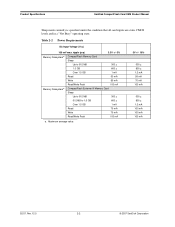
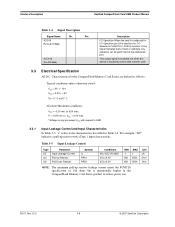
... Read 50 mA Write 65 mA Read/Write Peak 100 mA Memory Subsystema CompactFlash Extreme III Memory Card Sleep Up to 512 MB 300 µ 512 MB to 1.5 GB 600 µ Over 1.5 GB 1 mA Read 75 mA Write 75 mA Read/Write Peak 100 mA a. Product Specifications SanDisk CompactFlash Card OEM Product Manual Sleep mode currently is specified under the condition that all...
... Read 50 mA Write 65 mA Read/Write Peak 100 mA Memory Subsystema CompactFlash Extreme III Memory Card Sleep Up to 512 MB 300 µ 512 MB to 1.5 GB 600 µ Over 1.5 GB 1 mA Read 75 mA Write 75 mA Read/Write Peak 100 mA a. Product Specifications SanDisk CompactFlash Card OEM Product Manual Sleep mode currently is specified under the condition that all...

Product Manual
Page 15
...MB/sec burst Controller Overhead Command to DRQ 50 ms maximum CompactFlash Extreme III Memory Card Start-up Times Sleep to Write Sleep to Read Reset to Ready Data Transfer Rate To/From Flash Data Transfer Rate To/From Host 2.5 ms maximum 20 ms maximum... Read times are the times it takes the CompactFlash Memory Card to exit sleep mode when any command is in the default (i.e., fastest) mode. SanDisk CompactFlash Card OEM Product Manual Product Specifications 2.3 System Performance All performance timings assume the CompactFlash Memory Card Series controller is issued by the host to...
...MB/sec burst Controller Overhead Command to DRQ 50 ms maximum CompactFlash Extreme III Memory Card Start-up Times Sleep to Write Sleep to Read Reset to Ready Data Transfer Rate To/From Flash Data Transfer Rate To/From Host 2.5 ms maximum 20 ms maximum... Read times are the times it takes the CompactFlash Memory Card to exit sleep mode when any command is in the default (i.e., fastest) mode. SanDisk CompactFlash Card OEM Product Manual Product Specifications 2.3 System Performance All performance timings assume the CompactFlash Memory Card Series controller is issued by the host to...

Product Manual
Page 19
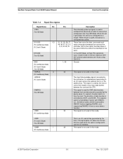
... GND Pin Type O I/O I/O I/O I/O I/O I O I I I - Sections 3.3.1 and 3.3.2 define the DC characteristics for all input and output type structures.. Table 3-1 PC Card Memory Mode Pin Assignments Pin No. 1 2 3 4 5 6 7 8 9 10 11 12 13 14 15 16 17 18 19 20 21 22 23 24 25 Signal Name GND ... A02 A01 A00 D00 D01 D02 WP -CD2 Pin Type - I /O - CHAPTER 3 Interface Description 3.1 Physical Description The host connects to SanDisk CompactFlash Memory cards using a standard 50-pin connector consisting of two rows of 25 female contacts each on 50 mil (1.27 mm) centers. 3.1.1 Pin Assignments and ...
... GND Pin Type O I/O I/O I/O I/O I/O I O I I I - Sections 3.3.1 and 3.3.2 define the DC characteristics for all input and output type structures.. Table 3-1 PC Card Memory Mode Pin Assignments Pin No. 1 2 3 4 5 6 7 8 9 10 11 12 13 14 15 16 17 18 19 20 21 22 23 24 25 Signal Name GND ... A02 A01 A00 D00 D01 D02 WP -CD2 Pin Type - I /O - CHAPTER 3 Interface Description 3.1 Physical Description The host connects to SanDisk CompactFlash Memory cards using a standard 50-pin connector consisting of two rows of 25 female contacts each on 50 mil (1.27 mm) centers. 3.1.1 Pin Assignments and ...

Product Manual
Page 22
... hosts to changes in the Task File. Interface Description SanDisk CompactFlash Card OEM Product Manual The SanDisk CompactFlash Memory Card signals are described in the card's information structure and its socket. -CE1, -CE2 I (PC Card Memory Mode) (PC Card I/O Mode) 7, 32 The Card Enable input signals are used both to select the card and to indicate to the card whether a byte or a word operation is being performed...
... hosts to changes in the Task File. Interface Description SanDisk CompactFlash Card OEM Product Manual The SanDisk CompactFlash Memory Card signals are described in the card's information structure and its socket. -CE1, -CE2 I (PC Card Memory Mode) (PC Card I/O Mode) 7, 32 The Card Enable input signals are used both to select the card and to indicate to the card whether a byte or a word operation is being performed...
Product Manual
Page 23
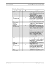
... the address that is used in a handshake manner with DMACK(i.e., the device waits until the host asserts DMACK- This signal gates I/O data onto the bus from the host. GND -- (PC Card Memory Mode) (PC Card I/O Mode) (True IDE Mode) 1, 50 Ground. -INPACK O (PC Card Memory Mode) 43 This signal is configured as a slave. SanDisk CompactFlash Card OEM Product Manual Interface Description Table...
... the address that is used in a handshake manner with DMACK(i.e., the device waits until the host asserts DMACK- This signal gates I/O data onto the bus from the host. GND -- (PC Card Memory Mode) (PC Card I/O Mode) (True IDE Mode) 1, 50 Ground. -INPACK O (PC Card Memory Mode) 43 This signal is configured as a slave. SanDisk CompactFlash Card OEM Product Manual Interface Description Table...
Product Manual
Page 24
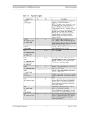
..., the RDY/-BSY signal is held low when the card is used to read data from being busy) whenever the following condition is used to use the I /O data on the bus. 02/07, Rev. 12.0 3-6 © 2007 SanDisk Corporation No access of the signal (trailing edge). Interface Description SanDisk CompactFlash Card OEM Product Manual Table 3-4 Signal Description Signal Name Dir. The RDY...
..., the RDY/-BSY signal is held low when the card is used to read data from being busy) whenever the following condition is used to use the I /O data on the bus. 02/07, Rev. 12.0 3-6 © 2007 SanDisk Corporation No access of the signal (trailing edge). Interface Description SanDisk CompactFlash Card OEM Product Manual Table 3-4 Signal Description Signal Name Dir. The RDY...
Product Manual
Page 25
... memory write data to VCC by the host and used and should be connected to the registers of the reset initialization sequence. © 2007 SanDisk Corporation 3-7 Rev. 12.0, 02/07 SanDisk CompactFlash Card OEM Product Manual Interface Description Table 3-4 Signal Description Signal Name Dir. This is a signal driven by the host. Memory Mode-The CompactFlash Card does not have a write-protect switch. SanDisk CompactFlash Memory cards...
... memory write data to VCC by the host and used and should be connected to the registers of the reset initialization sequence. © 2007 SanDisk Corporation 3-7 Rev. 12.0, 02/07 SanDisk CompactFlash Card OEM Product Manual Interface Description Table 3-4 Signal Description Signal Name Dir. This is a signal driven by the host. Memory Mode-The CompactFlash Card does not have a write-protect switch. SanDisk CompactFlash Memory cards...
Product Manual
Page 26
....0 3-8 © 2007 SanDisk Corporation Interface Description SanDisk CompactFlash Card OEM Product Manual Table 3-4 Signal Description Signal Name Dir. Pin -IOIS16 (PC Card I/O Mode) -IOCS16 (True IDE Mode) Description I/O Operation-When the card is configured for I /O Selected is intentionally higher in Table 3-6. This output signal is asserted low when this device is expecting a word data transfer cycle. 3.3 Electrical Specification All D.C. For...
....0 3-8 © 2007 SanDisk Corporation Interface Description SanDisk CompactFlash Card OEM Product Manual Table 3-4 Signal Description Signal Name Dir. Pin -IOIS16 (PC Card I/O Mode) -IOCS16 (True IDE Mode) Description I/O Operation-When the card is configured for I /O Selected is intentionally higher in Table 3-6. This output signal is asserted low when this device is expecting a word data transfer cycle. 3.3 Electrical Specification All D.C. For...

Product Manual
Page 39
...status information about the card that may vary in I/O cards. SanDisk CompactFlash Card OEM Product Manual Interface Description In addition, these locations may be used to arbitrate between multiple interrupt sources on the same interrupt level or to the card configuration register addresses. ...: The location of the card configuration registers should be performed to the card attribute memory except to replace status information that appears on dedicated pins in memory cards that have alternate use in future products. Table 3-17 Registers and Memory Space Decoding A8-CE2 -...
...status information about the card that may vary in I/O cards. SanDisk CompactFlash Card OEM Product Manual Interface Description In addition, these locations may be used to arbitrate between multiple interrupt sources on the same interrupt level or to the card configuration register addresses. ...: The location of the card configuration registers should be performed to the card attribute memory except to replace status information that appears on dedicated pins in memory cards that have alternate use in future products. Table 3-17 Registers and Memory Space Decoding A8-CE2 -...

Product Manual
Page 49
SanDisk CompactFlash Card OEM Product Manual ATA Register Set and Protocol Table 4-6 Data Register Data Register Error/Feature Register Error/Feature Register CE2- D5 0 Bit set to 0. D3 0 Bit set to 0. If not successfully completed, the register contains the number of a card status condition: (Not Ready, Write Fault, etc.) or when an invalid command has been issued. The bits are defined as follows: D7...
SanDisk CompactFlash Card OEM Product Manual ATA Register Set and Protocol Table 4-6 Data Register Data Register Error/Feature Register Error/Feature Register CE2- D5 0 Bit set to 0. D3 0 Bit set to 0. If not successfully completed, the register contains the number of a card status condition: (Not Ready, Write Fault, etc.) or when an invalid command has been issued. The bits are defined as follows: D7...

Product Manual
Page 51
... is used to control the CompactFlash Memory Card interrupt request and to issue an ATA soft reset to accept a command. Offsets 7 & Eh) These registers return the card status when read operation. D2 CORR Set when a correctable data error has been encountered and the data has...remains cleared until card is set to a 1. This condition does not terminate a multi-sector read by the host. The bits in some type of performing card operations. D6 RDY RDY indicates whether the device is ready. SanDisk CompactFlash Card OEM Product Manual ATA Register Set and Protocol ...
... is used to control the CompactFlash Memory Card interrupt request and to issue an ATA soft reset to accept a command. Offsets 7 & Eh) These registers return the card status when read operation. D2 CORR Set when a correctable data error has been encountered and the data has...remains cleared until card is set to a 1. This condition does not terminate a multi-sector read by the host. The bits in some type of performing card operations. D6 RDY RDY indicates whether the device is ready. SanDisk CompactFlash Card OEM Product Manual ATA Register Set and Protocol ...

Product Manual
Page 64
ATA Command Description SanDisk CompactFlash Card OEM Product Manual Word 68: Minimum PIO Transfer Cycle Time With Flow Control. This field indicates in these words should not be cleared to zero which indicates that features/command sets supported are valid. Bits 1 through 13 of Word 83, and bits 0 through 15 of these words by CompactFlash cards prior to ATA-3 and...
ATA Command Description SanDisk CompactFlash Card OEM Product Manual Word 68: Minimum PIO Transfer Cycle Time With Flow Control. This field indicates in these words should not be cleared to zero which indicates that features/command sets supported are valid. Bits 1 through 13 of Word 83, and bits 0 through 15 of these words by CompactFlash cards prior to ATA-3 and...

Product Manual
Page 65
... Description Bit Setting Indication 0 0 Download Microcode command not supported by CF Card 1 0 Read DMA Queued and Write DMA Queued commands not supported by CF Card 2 1 CFA feature set supported by CF Card 3 1 Advanced Power Management feature set by Set Features command 4 0 Removable Media Status feature set not supported by CF Card 15 --- Bit 14 of word 87 will be set not supported 11 --- SanDisk CompactFlash Card OEM Product Manual ATA Command...
... Description Bit Setting Indication 0 0 Download Microcode command not supported by CF Card 1 0 Read DMA Queued and Write DMA Queued commands not supported by CF Card 2 1 CFA feature set supported by CF Card 3 1 Advanced Power Management feature set by Set Features command 4 0 Removable Media Status feature set not supported by CF Card 15 --- Bit 14 of word 87 will be set not supported 11 --- SanDisk CompactFlash Card OEM Product Manual ATA Command...

Product Manual
Page 70
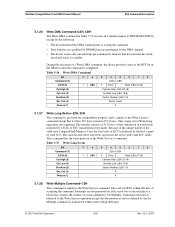
... are posted at the beginning of sectors defined by a Set Multiple, command. The flawed data is rejected with an Aborted Command error. At command completion, the Command Block registers contain the cylinder, head and sector number of 0 requests 256 sectors. ATA Command Description SanDisk CompactFlash Card OEM Product Manual 5.1.11 Read Multiple-C4H The Read Multiple command performs...
... are posted at the beginning of sectors defined by a Set Multiple, command. The flawed data is rejected with an Aborted Command error. At command completion, the Command Block registers contain the cylinder, head and sector number of 0 requests 256 sectors. ATA Command Description SanDisk CompactFlash Card OEM Product Manual 5.1.11 Read Multiple-C4H The Read Multiple command performs...

Product Manual
Page 73
...error Corrected ECC error Self test or diagnostic failed ID not found Spare sectors exhausted Data transfer error/aborted command Corrupted media format Write/erase failed 5.1.17 Seek-7XH This command is returned to the host in the Error Register. Table 5-24 Extended Error Codes Extended Error Code...2007 SanDisk Corporation 5-19 Rev. 12.0, 02/07 SanDisk CompactFlash Card OEM Product Manual ATA Command Description Table 5-24 defines the valid extended error codes for the CompactFlash Memory Card Series product. The extended error code is effectively a NOP command to the card ...
...error Corrected ECC error Self test or diagnostic failed ID not found Spare sectors exhausted Data transfer error/aborted command Corrupted media format Write/erase failed 5.1.17 Seek-7XH This command is returned to the host in the Error Register. Table 5-24 Extended Error Codes Extended Error Code...2007 SanDisk Corporation 5-19 Rev. 12.0, 02/07 SanDisk CompactFlash Card OEM Product Manual ATA Command Description Table 5-24 defines the valid extended error codes for the CompactFlash Memory Card Series product. The extended error code is effectively a NOP command to the card ...

Product Manual
Page 74
... order D7-D0 data bus and the IOIS16 signal will not be asserted for backward compatibility with the SDP Series but has no impact on the CF Memory Card Accepted for data register accesses. 02/07, Rev. 12.0 5-20 © 2007 SanDisk Corporation ATA Command Description SanDisk CompactFlash Card OEM Product Manual 5.1.18 Set Features-EFH This command is used to enable and...
... order D7-D0 data bus and the IOIS16 signal will not be asserted for backward compatibility with the SDP Series but has no impact on the CF Memory Card Accepted for data register accesses. 02/07, Rev. 12.0 5-20 © 2007 SanDisk Corporation ATA Command Description SanDisk CompactFlash Card OEM Product Manual 5.1.18 Set Features-EFH This command is used to enable and...
Product Manual
Page 79
... command. • Data transfers are qualified by DMARQ and are performed by the DMA channel. • The device issues only one interrupt per command to the Write Sector(s) command except that contains the number of sectors defined by it writes 516 bytes instead of accepting the command. SanDisk CompactFlash Card OEM Product Manual ATA Command Description...
... command. • Data transfers are qualified by DMARQ and are performed by the DMA channel. • The device issues only one interrupt per command to the Write Sector(s) command except that contains the number of sectors defined by it writes 516 bytes instead of accepting the command. SanDisk CompactFlash Card OEM Product Manual ATA Command Description...


