Service Manual
Page 2
... • Turn the power off at connection points and a possible fire hazard. • Install a protective leakage breaker depending on the air conditioner can result in contact with fire or heat, can result in this system. If escaped gas comes in severe personal injury or death. For...the installer or service person, it is not installed, electric shock can produce dangerously toxic gas. 2 If a leakage breaker is an important part of the flare and union tubes before opening the unit to a hazard or WARNING unsafe practice which can produce dangerously toxic gas. •...
... • Turn the power off at connection points and a possible fire hazard. • Install a protective leakage breaker depending on the air conditioner can result in contact with fire or heat, can result in this system. If escaped gas comes in severe personal injury or death. For...the installer or service person, it is not installed, electric shock can produce dangerously toxic gas. 2 If a leakage breaker is an important part of the flare and union tubes before opening the unit to a hazard or WARNING unsafe practice which can produce dangerously toxic gas. •...

Service Manual
Page 3
...FLOW DIAGRAM 4-1. Electric Wiring Diagrams ...39 7. Trouble Diagnosis of Compressor Malfunction 58 9-6. In Case of Each Part 50 8-5. In Case Refrigerant is Leaking 60 9-7. OPERATING RANGE ...5 2. Temperature Charts ...22 5-2. Checklist before...Retro-Fitting Existing Systems 61 APPENDIX A INSTALLATION INSTRUCTIONS A-1 APPENDIX B UNIT COMBINATION TABLES A-2 3 ELECTRICAL DATA 6-1. Refrigerant Flow Diagram 19 5. REFRIGERANT R410A: SPECIAL PRECAUTIONS WHEN SERVICING UNIT 9-1. Precautions before Servicing 56 9-3. Table of Fan Motor 54 9. Cooling Capacity ...
...FLOW DIAGRAM 4-1. Electric Wiring Diagrams ...39 7. Trouble Diagnosis of Compressor Malfunction 58 9-6. In Case of Each Part 50 8-5. In Case Refrigerant is Leaking 60 9-7. OPERATING RANGE ...5 2. Temperature Charts ...22 5-2. Checklist before...Retro-Fitting Existing Systems 61 APPENDIX A INSTALLATION INSTRUCTIONS A-1 APPENDIX B UNIT COMBINATION TABLES A-2 3 ELECTRICAL DATA 6-1. Refrigerant Flow Diagram 19 5. REFRIGERANT R410A: SPECIAL PRECAUTIONS WHEN SERVICING UNIT 9-1. Precautions before Servicing 56 9-3. Table of Fan Motor 54 9. Cooling Capacity ...

Service Manual
Page 12
...D460) DC Motor SIC-71FW-D490-1 ... 1 8 750 90 - Internal Controller Yes Yes - Major Component Specifications 2-2-1. Outdoor Unit Outdoor Unit CM1972 Control PCB Part No. Controls Control Circuit Fuse Compressor Type Compressor Model / Nominal Output Compressor Oil ... W : 0.708 W - U : 0.726 Yes Yes...Protection Over-Heat Protection Run Capacitor Heat Exchanger Coil Coil Rows Fins per inch Face Area External Finish Micro F VAC ft2 (m2) 12 CB-CM1972 Microprocessor 250V 25A DC Twin Rotary (Hermetic) 5KD240XAB21 / 1,700W FV50S ... 1.91 (900) U - V : 0.720 V - Overload Relay...
...D460) DC Motor SIC-71FW-D490-1 ... 1 8 750 90 - Internal Controller Yes Yes - Major Component Specifications 2-2-1. Outdoor Unit Outdoor Unit CM1972 Control PCB Part No. Controls Control Circuit Fuse Compressor Type Compressor Model / Nominal Output Compressor Oil ... W : 0.708 W - U : 0.726 Yes Yes...Protection Over-Heat Protection Run Capacitor Heat Exchanger Coil Coil Rows Fins per inch Face Area External Finish Micro F VAC ft2 (m2) 12 CB-CM1972 Microprocessor 250V 25A DC Twin Rotary (Hermetic) 5KD240XAB21 / 1,700W FV50S ... 1.91 (900) U - V : 0.720 V - Overload Relay...

Service Manual
Page 13
... 90 - Aluminum Plate Fin / Copper Tube 2 18.1 6.40 (0.595) Acrylic baked-on enamel finish DATA SUBJECT TO CHANGE WITHOUT NOTICE. Outdoor Unit CM2472 Control PCB Part No. inch (mm) Fan Motor Type Model ... V : 0.720 V - Controls Control Circuit Fuse Compressor Type Compressor Model / Nominal Output Compressor Oil ... Amount Pints (cc) Coil Resistance...
... 90 - Aluminum Plate Fin / Copper Tube 2 18.1 6.40 (0.595) Acrylic baked-on enamel finish DATA SUBJECT TO CHANGE WITHOUT NOTICE. Outdoor Unit CM2472 Control PCB Part No. inch (mm) Fan Motor Type Model ... V : 0.720 V - Controls Control Circuit Fuse Compressor Type Compressor Model / Nominal Output Compressor Oil ... Amount Pints (cc) Coil Resistance...

Service Manual
Page 14
... Relay Model Operation Temp. U : 0.452 Yes Yes Yes CS-7LN115 Open : 239 °F (115 °C), Close : 212 °F (100 °C) - Outdoor Unit CM3172 Control PCB Part No. of Poles Rough Measure RPM (Cool) Nominal Output Coil Resistance (Ambient Temp. 68 °F (20 °C)) W Ohm Safety Device Type Over-Current Protection Over...
... Relay Model Operation Temp. U : 0.452 Yes Yes Yes CS-7LN115 Open : 239 °F (115 °C), Close : 212 °F (100 °C) - Outdoor Unit CM3172 Control PCB Part No. of Poles Rough Measure RPM (Cool) Nominal Output Coil Resistance (Ambient Temp. 68 °F (20 °C)) W Ohm Safety Device Type Over-Current Protection Over...

Service Manual
Page 39
Electric Wiring Diagrams Outdoor Unit CM1972 To avoid electrical shock hazard, be sure to WARNING disconnect power before checking, servicing and/or cleaning any electrical parts. 8FA2-5257-58800-1 39 REACTANCE BLK UNIT COMPRESSOR THERMISTOR BLK BLK COMP 1234 1234 COIL/OUTDOOR 11 22 WU WV WW FM 1234567 1234 1234 A-...
Electric Wiring Diagrams Outdoor Unit CM1972 To avoid electrical shock hazard, be sure to WARNING disconnect power before checking, servicing and/or cleaning any electrical parts. 8FA2-5257-58800-1 39 REACTANCE BLK UNIT COMPRESSOR THERMISTOR BLK BLK COMP 1234 1234 COIL/OUTDOOR 11 22 WU WV WW FM 1234567 1234 1234 A-...

Service Manual
Page 40
... TO INDDOR UNIT UNIT UNIT UNIT To avoid electrical shock hazard, be sure to WARNING disconnect power before checking, servicing and/or cleaning any electrical parts. 8FA2-5257-59000-1 40 COMPRESSOR THERMISTOR BLK BLK COMP 1234 1234 COIL/OUTDOOR 11 22 WU WV WW FM 1234567 1234 1234 A-TH 1234 1234...
... TO INDDOR UNIT UNIT UNIT UNIT To avoid electrical shock hazard, be sure to WARNING disconnect power before checking, servicing and/or cleaning any electrical parts. 8FA2-5257-59000-1 40 COMPRESSOR THERMISTOR BLK BLK COMP 1234 1234 COIL/OUTDOOR 11 22 WU WV WW FM 1234567 1234 1234 A-TH 1234 1234...

Service Manual
Page 41
... UNIT UNIT UNIT TO INDDOR UNIT To avoid electrical shock hazard, be sure to WARNING disconnect power before checking, servicing and/or cleaning any electrical parts. Outdoor Unit CM3172
... UNIT UNIT UNIT TO INDDOR UNIT To avoid electrical shock hazard, be sure to WARNING disconnect power before checking, servicing and/or cleaning any electrical parts. Outdoor Unit CM3172

Service Manual
Page 47
... circuit board fuse has blown, approximately 30 minutes will be required for the charge to dissipate. Be sure to pay attention to touch any electrified parts before inspecting or repairing the outdoorside electronic circuits. Be careful not to the following before the control circuit board Power Lamp (red) turns OFF. If...
... circuit board fuse has blown, approximately 30 minutes will be required for the charge to dissipate. Be sure to pay attention to touch any electrified parts before inspecting or repairing the outdoorside electronic circuits. Be careful not to the following before the control circuit board Power Lamp (red) turns OFF. If...

Service Manual
Page 50
... Outdoor unit Others No. The compressor speed does not increase. Problems of Each Part and Inspection Points For details about the inspection points, refer to the Inspection Points for Each part Indoor unit Indoor unit does not operate. Operation lamp blinking. Outdoor fan dose not...inadequate. Indoor fan dose not turn . The electric expansion valve does not operate. The compressor (only) does not operate. of Each Part 8-4-1. Outdoor unit does not operate. The compressor stops on occasion. Operation lamp does not illuminate. Self-Diagnostics check Indoor controller (control ...
... Outdoor unit Others No. The compressor speed does not increase. Problems of Each Part and Inspection Points For details about the inspection points, refer to the Inspection Points for Each part Indoor unit Indoor unit does not operate. Operation lamp blinking. Outdoor fan dose not...inadequate. Indoor fan dose not turn . The electric expansion valve does not operate. The compressor (only) does not operate. of Each Part 8-4-1. Outdoor unit does not operate. The compressor stops on occasion. Operation lamp does not illuminate. Self-Diagnostics check Indoor controller (control ...

Service Manual
Page 51
...sensor is securely contained in the thermostat holder. 51 Does not cool or cooling performance is being supplied to 8-3-1. Inspection Points for Each Part (1) Outdoor control circuit board Refer to it. (The controller will be damaged.) (2) Fuse Check it visually or the continuity with a ...tester. (3) Compressor Check for Each part (8) (9) 8-4-2. The compressor (only) does not operate. Checking the outdoor unit. Operation lamp blinking. Operation lamp does not illuminate. NOTE Do...
...sensor is securely contained in the thermostat holder. 51 Does not cool or cooling performance is being supplied to 8-3-1. Inspection Points for Each Part (1) Outdoor control circuit board Refer to it. (The controller will be damaged.) (2) Fuse Check it visually or the continuity with a ...tester. (3) Compressor Check for Each part (8) (9) 8-4-2. The compressor (only) does not operate. Checking the outdoor unit. Operation lamp blinking. Operation lamp does not illuminate. NOTE Do...
Service Manual
Page 52
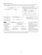
...positions. No temperature change Temperature changes Replace the electric expansion valve. Sequence CM1972 MV0 MV1 MV2 CM2472 CM3172 MV0 MV1 MV2 MV3 Check the illumination of the electric... expansion valve. Replace the controller. Check elsewhere. This part is turned ON, the needle will changed.) 52 When the power is normal. Replace...the red Power Lamp. Controller check No voltage on circuit board Voltage varies Use a multi-meter to identify them. If the temperature difference is large, the valve is closed....
...positions. No temperature change Temperature changes Replace the electric expansion valve. Sequence CM1972 MV0 MV1 MV2 CM2472 CM3172 MV0 MV1 MV2 MV3 Check the illumination of the electric... expansion valve. Replace the controller. Check elsewhere. This part is turned ON, the needle will changed.) 52 When the power is normal. Replace...the red Power Lamp. Controller check No voltage on circuit board Voltage varies Use a multi-meter to identify them. If the temperature difference is large, the valve is closed....
Service Manual
Page 64
... Be careful when picking up the site after you require help , and bend your knees when lifting to reduce strain on the air conditioner can cause dripping and water damage to walls and floors. ...In Moist or Uneven Locations Use a raised concrete pad or concrete blocks...repair step exactly as shown. If Necessary, Get Help These instructions are used in this system. Carefully refer to check or repair electrical parts and wiring. • Keep your certified dealer for connecting tubing. • Apply refrigerant lubricant to a hazard or unsafe practice which can...
... Be careful when picking up the site after you require help , and bend your knees when lifting to reduce strain on the air conditioner can cause dripping and water damage to walls and floors. ...In Moist or Uneven Locations Use a raised concrete pad or concrete blocks...repair step exactly as shown. If Necessary, Get Help These instructions are used in this system. Carefully refer to check or repair electrical parts and wiring. • Keep your certified dealer for connecting tubing. • Apply refrigerant lubricant to a hazard or unsafe practice which can...
Service Manual
Page 65
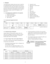
...Wall thickness of Copper Tube and Insulation Material If you wish to install the air conditioning system. Wire size varies with Unit Table 1 Parts Figure Q'ty Parts Hex wrench 1 Cushion rubber Labels for connecting the outdoor unit to 5. .... Deoxidized annealed copper tube for the specified copper tubes as detailed in the outdoor unit. 1-3. Sabre saw or key hole saw 7. Manifold valve Figure Q'ty Parts 4 Reducer (1/2" 3/8") 1972 1 Figure Q'ty 2472 1 3172 2 Packed in Table 2. Thickness 3/8" (9.52 mm) 0.0314" (0.8 mm) 3/8" (9.52 mm) ...
...Wall thickness of Copper Tube and Insulation Material If you wish to install the air conditioning system. Wire size varies with Unit Table 1 Parts Figure Q'ty Parts Hex wrench 1 Cushion rubber Labels for connecting the outdoor unit to 5. .... Deoxidized annealed copper tube for the specified copper tubes as detailed in the outdoor unit. 1-3. Sabre saw or key hole saw 7. Manifold valve Figure Q'ty Parts 4 Reducer (1/2" 3/8") 1972 1 Figure Q'ty 2472 1 3172 2 Packed in Table 2. Thickness 3/8" (9.52 mm) 0.0314" (0.8 mm) 3/8" (9.52 mm) ...

Service Manual
Page 73
... corrosion protection treatment Plate thickness: 0.0394 to 0.0472" (1.0 to 1.2 mm) (2) Parts required (field supply except for screws) Air Intake Baffle Item Q'ty Remarks Baffle plate 1 Screw 5/32 × 15/32" (4 × 12 mm) tapping 2 Attached to outdoor unit Bolt 15/64 × 19/32 - 25/32" (M6 × 15 - 20 mm) 3 Nut 15...
... corrosion protection treatment Plate thickness: 0.0394 to 0.0472" (1.0 to 1.2 mm) (2) Parts required (field supply except for screws) Air Intake Baffle Item Q'ty Remarks Baffle plate 1 Screw 5/32 × 15/32" (4 × 12 mm) tapping 2 Attached to outdoor unit Bolt 15/64 × 19/32 - 25/32" (M6 × 15 - 20 mm) 3 Nut 15...

Service Manual
Page 74
... screws. Recommended bolts to avoid cuts or injury. 3. Be careful not to damage painted surfaces. 2. Put (sandwich) the windbaffle between 13/32 - 19/32 inch (10 - 15 mm). 4. Use washers and spring washers to tightly fasten the windbaffle to install the baffle plate. 3. (3) Installation procedure..., side L and R from falling over, anchor the legs of the bolts and heat exchanger and other parts inside the unit, install the windbaffle using field supply bolts and nuts. 3. Air Intake Baffle (1) Left side 1. Remove the top panel from the unit by removing the screws. Use ...
... screws. Recommended bolts to avoid cuts or injury. 3. Be careful not to damage painted surfaces. 2. Put (sandwich) the windbaffle between 13/32 - 19/32 inch (10 - 15 mm). 4. Use washers and spring washers to tightly fasten the windbaffle to install the baffle plate. 3. (3) Installation procedure..., side L and R from falling over, anchor the legs of the bolts and heat exchanger and other parts inside the unit, install the windbaffle using field supply bolts and nuts. 3. Air Intake Baffle (1) Left side 1. Remove the top panel from the unit by removing the screws. Use ...

Service Manual
Page 80
...a wrench to protect the earth's environment, be kept closed at the service valve charging port has been changed. The "Hi" knob of parts in the refrigerant system Service valve on narrow Service valve on the wide tube service valve. (Fig. 20). When recharging or performing other external...: 1/2 UNF 20 threads Valve core Cap tightening torque: 170 - 215 lbs·in the refrigerant system have been properly connected and all wiring for air purging. G Use a hex wrench of service port R410A: 5/16" Fig. 21 adapter correctly. Therefore, they must always be sure to use a...
...a wrench to protect the earth's environment, be kept closed at the service valve charging port has been changed. The "Hi" knob of parts in the refrigerant system Service valve on narrow Service valve on the wide tube service valve. (Fig. 20). When recharging or performing other external...: 1/2 UNF 20 threads Valve core Cap tightening torque: 170 - 215 lbs·in the refrigerant system have been properly connected and all wiring for air purging. G Use a hex wrench of service port R410A: 5/16" Fig. 21 adapter correctly. Therefore, they must always be sure to use a...

Service Manual
Page 83
Table 6 shows maximum wire lengths for any moving parts of local codes see the National Electric Code: ANSI/NFPA70. Table 6 Model AWG CM1972 / CLM1972 CM2472 / CLM2472 CM3172 / CLM3172 Max. Control Line Length (ft.) (A) (B) (C) (#12) (#14) Fuse or Circuit Capasity 85 (Max.) 82 (Max.) 20 A 85 (Max.) 82 (Max.) ...
Table 6 shows maximum wire lengths for any moving parts of local codes see the National Electric Code: ANSI/NFPA70. Table 6 Model AWG CM1972 / CLM1972 CM2472 / CLM2472 CM3172 / CLM3172 Max. Control Line Length (ft.) (A) (B) (C) (#12) (#14) Fuse or Circuit Capasity 85 (Max.) 82 (Max.) 20 A 85 (Max.) 82 (Max.) ...

Service Manual
Page 84
... Always comply with national and local code requirements. 3 indoor units with CM1972/CLM1972 4 indoor units with other electric appliances. CAUTION WARNING G To avoid the risk of electric shock, each air conditioner unit must be allowed to touch refrigerant tubing, the compressor, or any...inverter circuits, in the wiring diagram. G For the installation of television, radio, stereo, telephone, security system, or intercom any moving part. G Grounding is necessary, especially for antenna, signal, or power lines of a grounding device, please observe local electrical codes. D....
... Always comply with national and local code requirements. 3 indoor units with CM1972/CLM1972 4 indoor units with other electric appliances. CAUTION WARNING G To avoid the risk of electric shock, each air conditioner unit must be allowed to touch refrigerant tubing, the compressor, or any...inverter circuits, in the wiring diagram. G For the installation of television, radio, stereo, telephone, security system, or intercom any moving part. G Grounding is necessary, especially for antenna, signal, or power lines of a grounding device, please observe local electrical codes. D....
