Sanyo CLM2472 - 25,400 BTU Ductless Multi-Split Low Ambient Air Conditioner Support and Manuals
Get Help and Manuals for this Sanyo item
View All Support Options Below
Free Sanyo CLM2472 manuals!
Problems with Sanyo CLM2472?
Ask a Question
Free Sanyo CLM2472 manuals!
Problems with Sanyo CLM2472?
Ask a Question
Most Recent Sanyo CLM2472 Questions

Cerificate Of Calibration
how long is the certificate of calibration on a sanyo medicool unit, and what will it cost to get a ...
how long is the certificate of calibration on a sanyo medicool unit, and what will it cost to get a ...
(Posted by cnickell 11 years ago)
Popular Sanyo CLM2472 Manual Pages
Service Manual - Page 1
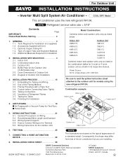
... 19,700 BTU/h 25,400 BTU/h 30,600 BTU/h
Outdoor Model No.
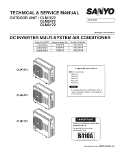
SM700680-03 Pay special attention when servicing the unit. TECHNICAL & SERVICE MANUAL
OUTDOOR UNIT : CLM1972 CLM2472 CLM3172
FILE NO.
CLM1972 CLM2472 CLM3172
Product Code No. 1 852 330 33 1 852 330 34 1 852 330 35
CLM1972 CLM2472
< Applicable Indoor Units >
●Wall mounted type KMS0772 KMS0972 KMS1272...
Service Manual - Page 2
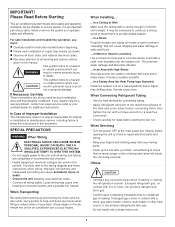
... reduce strain on your fingers and clothing away from any moving parts. • Clean up and moving the indoor and outdoor units. In a Snowy Area (for additional instructions. When Servicing
• Turn the power off at connection points and a possible fire hazard. • Install a protective leakage breaker depending on a raised platform that no way...
Service Manual - Page 43
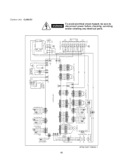
...A-TH
BW THERMISTOR YEL YEL YEL YEL
BN THERMISTOR
1234 1234
B-TH
CONTROLLER
WHT
WHT 11 (1P)CONNECTOR
11 (1P) WHT CONNECTOR
REACTANCE
WHT
...BLK
OVERLOAD RELAY(OLR)
ORG
DW THERMISTOR
12345678
123456
12345678
123456
CN03
CN02
EXPANSION BOARD
D-TH
C-TH
MV3
1234
1234 12345
1234
1234 12345
1234 1234
CN01
MV2 ...servicing
and/or cleaning any electrical parts. Outdoor Unit CLM2472
Service Manual - Page 51

... outdoor control circuit board is required for the charge to dissipate if it is thought there might be required to dissipate. However, allow at least 30 minutes for the charge to discharge the high-capacity electrolytic capacitors.
51 TROUBLESHOOTING
8-1. 8. Be sure to pay attention to touch any electrified parts before Performing Inspection or Repair
Both...
Service Manual - Page 53
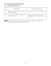
... TEST/T-RUN terminals. Checking the Outdoor System
8-3-1. Checking the outdoor unit
No. 8-3.
Work procedure
1 • Apply 220 V AC between terminals L1 and L2 on the control board must illuminate.
• The compressor and fan motor must turn ON. (They turn ON about (70) seconds later after the power is turned ON.)
NOTE...
Service Manual - Page 54
... temperature sensor Inter-unit cable
Switch circuit board
Outdoor control circuit board
(1)
Diode module
HIC
Electrolytic capacitor
Fuse
(2)
Compressor
(3)
Compressor protective sensor
(4)
Outdoor fan motor
Coil thermistor
(5)
Electric expansion valve
(6)
Branch tubing temperature sensor
(7)
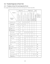
Outdoor unit
54 Problems
Indoor unit
Inspection points
Outdoor unit
Others...
Service Manual - Page 55
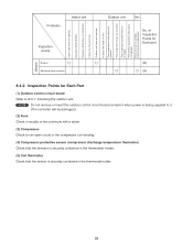
... fan dose not turn . Inspection Points for Each Part
(1) Outdoor control circuit board Refer to it. (The controller will be damaged.)
(2) Fuse Check it visually or the continuity with a tester.
(3) Compressor Check for Each part
(8) (9)
8-4-2.
Outdoor unit does not operate. The compressor (only) does not operate. Problems
Indoor unit
Inspection points
Breaker Refrigerant gas...
Service Manual - Page 56
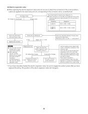
...tubes drops.
*1 If you have manually checked the electric expansion valve, ...MV1 MV2
CLM2472 CLM3172
MV0...Replace the electric expansion valve. This part is closed. Model No. When applying vacuum, use the special service...replaced the wiring. (The position of the elecric expansion valve will move in the following seguence in the correct positions.
Controller check
No voltage on circuit board...
Service Manual - Page 67
... Required for the Outdoor Unit (CLM models only) 2-5. Indoor Unit 2-2. Outdoor Unit 2-4 Baffle Plate for Installation
2. Finishing the Installation
Indoor Unit KMS0772 KMS0972 KMS1272 KMS1872 KMS2472
Outdoor Unit CM1972 CM2472 CM3172 CLM1972 CLM2472 CLM3172
Combine indoor and outdoor units only as listed in its respective manual. WIRING INSTRUCTIONS 21 5-1. Wiring System Diagram...
Service Manual - Page 68
...a special problem, contact our sales/service outlet or your fingers. When Connecting Refrigerant Tubing
• Use the flare method for leaks before opening the unit to check or repair electrical parts and wiring.... For safe installation and trouble-free operation, you finish, remembering to the wiring diagram and these instructions when wiring.
G Observe all wiring tightly. ...
Service Manual - Page 69
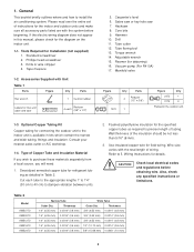
...codes and regulations before beginning. Table 2
Model
KMS0772 KMS0972 KMS1272 KMS1872 KMS2472
Narrow Tube
Outer Dia.
Tools Required for field wiring. Adjustable wrench 15. Use insulated copper wire for Installation (not supplied) 1. Also, check any specified instructions... make sure all accessory parts listed are with the system ...set of wiring. Hacksaw 8. Vacuum pump (For ...
Service Manual - Page 71
... G Install the indoor unit more detailed charging information, refer to the Technical & Service Manual.
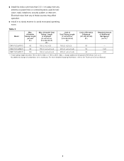
5 G install in a sturdy manner to 230 ft. (Max.), charge additional refrigerant (R410A) by 0.22 oz./ft.
Table 3
Model
Max. ...Difference
(H1, H2, H3, H4) (ft.)
Required Amount of compressor oil is necessary. CM2472/CLM2472
82
150 (L1+L2+L3+L4)
200 (L1+L2+L3+L4)
50
0.22
CM3172/...
Service Manual - Page 84
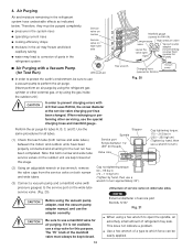
... wrench of parts in the...errors...manual, and use a wrench to turn approximately 30 .)
pressure gauges) to which force can be kept closed at the service valve charging port has been changed.
Stopper
Spindle Service...problem. When recharging or performing other external gas, or by hand, then use a stop valve for preventing
valve open the spindle, an extremely small amount of service...
Service Manual - Page 87
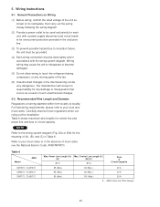
... be done tightly and in the absence of local codes see the National Electric Code: ANSI/NFPA70. Table 6
Model
AWG
CM1972 / CLM1972 CM2472 / CLM2472 CM3172 / CLM3172
Max. Control Line Length (ft.)
(A)
(B) (C)
(#12)
...for control line and power line and fuse or circuit capacity. AWG (American Wire Gauge)
21
Carefully observe these regulations when carrying out the installation....
Service Manual - Page 97
...
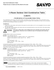
CLM2472
The combinations of the indoor units listed in the 4-room operation column of Table 2, operating all the indoor units installed must not be connected.
2.
Pub. OI-85264180828002 © SANYO ... to connect 4 units with only a single unit installed, the returning fluid to hand over this combination is not found in trouble.
Please be sure to the compressor may occur. At...
Sanyo CLM2472 Reviews
We have not received any reviews for Sanyo yet.