
Service Manual
Page 1
... MAIN PARTS ...7 ADJUSTMENT ...9 TEST MODE ...10 BLOCK DIAGRAM ...12 SCHEMATIC DIAGRAM / WIRING SIDE OF P.W.BOARD 16 VOLTAGE ...33 NOTES ON SCHEMATIC DIAGRAM ...34 TYPES OF TRANSISTOR ...34 FUNCTION TABLE OF IC ...35 FL DISPLAY ...39 REPLACEMENT PARTS LIST/EXPLODED VIEW PACKING OF THE SET SHARP CORPORATION This document has been published to change without notice. The contents are subject to be used for after sales service only. S4234CPXP120/ MINI COMPONENT SYSTEM MODEL CD-XP120 CD-XP120 Mini Component System...
... MAIN PARTS ...7 ADJUSTMENT ...9 TEST MODE ...10 BLOCK DIAGRAM ...12 SCHEMATIC DIAGRAM / WIRING SIDE OF P.W.BOARD 16 VOLTAGE ...33 NOTES ON SCHEMATIC DIAGRAM ...34 TYPES OF TRANSISTOR ...34 FUNCTION TABLE OF IC ...35 FL DISPLAY ...39 REPLACEMENT PARTS LIST/EXPLODED VIEW PACKING OF THE SET SHARP CORPORATION This document has been published to change without notice. The contents are subject to be used for after sales service only. S4234CPXP120/ MINI COMPONENT SYSTEM MODEL CD-XP120 CD-XP120 Mini Component System...
Service Manual
Page 2
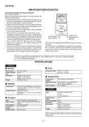
...) Amplifier Output power Output terminals 20 watts minimum RMS per volt, or higher, sensitivity to the owner. AC.) or more is not lodged between the chassis and other metal parts in series with 1000 ohm per channel into 8 ohms from 100 Hz to 20 kHz, 10% total harmonic distortion Speakers: 8 ohms Headphones: 16 - 50 ohms (recommended: 32 ohms) CD player Type Signal readout D/A converter Frequency response Dynamic range 3-disc multi-play compact disc player Non...
...) Amplifier Output power Output terminals 20 watts minimum RMS per volt, or higher, sensitivity to the owner. AC.) or more is not lodged between the chassis and other metal parts in series with 1000 ohm per channel into 8 ohms from 100 Hz to 20 kHz, 10% total harmonic distortion Speakers: 8 ohms Headphones: 16 - 50 ohms (recommended: 32 ohms) CD player Type Signal readout D/A converter Frequency response Dynamic range 3-disc multi-play compact disc player Non...
Service Manual
Page 3
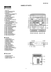
...Tape 2 Cassette Compartment 19. Tape 2 Stop/Eject Button Display 1. Clock Indicator 7. Tuner (Band) Button 4. Headphone Jack 7. Tape 1 Cassette Compartment 12. Tape Button 13. Volume Up and Down Buttons 18. CD Stop Button 8. Tape 2 Rewind Button 27. Disc Number Indicators 6. AC Power Input Jack 2. CD Repeat Play Indicator 3. FM Stereo Receiving Indicator 13. FM/AM Loop Antenna Jack 4. CD-XP120 Front panel 1. Disc Tray 2. Transport Screw 3. AM Station Indicator 5. Memory Indicator 14. FM Stereo Mode Indicator 12. Speaker Terminals NAMES OF PARTS CD-XP120...
...Tape 2 Cassette Compartment 19. Tape 2 Stop/Eject Button Display 1. Clock Indicator 7. Tuner (Band) Button 4. Headphone Jack 7. Tape 1 Cassette Compartment 12. Tape Button 13. Volume Up and Down Buttons 18. CD Stop Button 8. Tape 2 Rewind Button 27. Disc Number Indicators 6. AC Power Input Jack 2. CD Repeat Play Indicator 3. FM Stereo Receiving Indicator 13. FM/AM Loop Antenna Jack 4. CD-XP120 Front panel 1. Disc Tray 2. Transport Screw 3. AM Station Indicator 5. Memory Indicator 14. FM Stereo Mode Indicator 12. Speaker Terminals NAMES OF PARTS CD-XP120...
Service Manual
Page 4
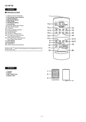
Memory/Set Button 5. Power On/Stand-by Button 12. Tape Button 20. Bass Reflex Duct 4. Speaker Wire 1 2 3 4 - 4 - Disc Number Select Buttons 3. Clear Button 6. CD Track Up or Fast Forward, Tuner Preset Up Button 16. Clock Button 8. CD Stop Button 14. CD Pause Button 4. CD Button 11. CD Play or Repeat Button 15. Equalizer Mode Select Button 9. Tuner (Band) Button 10. Sleep Button 19. CD Track Down or Fast Reverse, Tuner Preset Down Button 17. Volume Up and Down Buttons 1 2 3 13 4 14 5 15 6 16 7 17 8 18 9 10 19 Buttons with " " mark in the...
Memory/Set Button 5. Power On/Stand-by Button 12. Tape Button 20. Bass Reflex Duct 4. Speaker Wire 1 2 3 4 - 4 - Disc Number Select Buttons 3. Clear Button 6. CD Track Up or Fast Forward, Tuner Preset Up Button 16. Clock Button 8. CD Stop Button 14. CD Pause Button 4. CD Button 11. CD Play or Repeat Button 15. Equalizer Mode Select Button 9. Tuner (Band) Button 10. Sleep Button 19. CD Track Down or Fast Reverse, Tuner Preset Down Button 17. Volume Up and Down Buttons 1 2 3 13 4 14 5 15 6 16 7 17 8 18 9 10 19 Buttons with " " mark in the...

Service Manual
Page 5
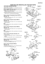
... 5-3 6 Front Panel 1. Screw P1) x2 6-3 15 CD Mechanism 1. Hook C2) x2 4. Screw N1) x3 6-3 (Note 1) 2. Screw B1) x6 5-1 3 CD Player Unit 1. Hook F2) x2 7 Switch A PWB 1. Spacer L2) x1 12 Loading Tray 1. Socket N2) x5 14 Switch B PWB 1. Socket G2) x1 8 Display PWB 1. Open the cassette holder. 6-1 2. Screw K1) x1 6-1 11 Turntable 1. After removing the connector for the optical pickup...
... 5-3 6 Front Panel 1. Screw P1) x2 6-3 15 CD Mechanism 1. Hook C2) x2 4. Screw N1) x3 6-3 (Note 1) 2. Screw B1) x6 5-1 3 CD Player Unit 1. Hook F2) x2 7 Switch A PWB 1. Spacer L2) x1 12 Loading Tray 1. Socket N2) x5 14 Switch B PWB 1. Socket G2) x1 8 Display PWB 1. Open the cassette holder. 6-1 2. Screw K1) x1 6-1 11 Turntable 1. After removing the connector for the optical pickup...
Service Manual
Page 7
Move the hooks (A2) x 2 pcs., toward the center position as shown in Fig. 7-1 and then lift the erase head. Note: When installing the pinch roller, pay attention to the spring mounting position. Note: When installing the pinch roller, pay attention to the spring mounting position. Remove ...1 pc. How to remove the pinch roller (TAPE 1) (See Fig. 7-3) 1. How to remove the playback head (TAPE 2) (See Fig. 7-2) 1. Remove the FF/REW belt (G2) x 1 pc. How to remove the tape mechanism. CD-XP120 REMOVING AND REINSTALLING THE MAIN PARTS TAPE MECHANISM SECTION Perform steps 1 to 6 and ...
Move the hooks (A2) x 2 pcs., toward the center position as shown in Fig. 7-1 and then lift the erase head. Note: When installing the pinch roller, pay attention to the spring mounting position. Note: When installing the pinch roller, pay attention to the spring mounting position. Remove ...1 pc. How to remove the pinch roller (TAPE 1) (See Fig. 7-3) 1. How to remove the playback head (TAPE 2) (See Fig. 7-2) 1. Remove the FF/REW belt (G2) x 1 pc. How to remove the tape mechanism. CD-XP120 REMOVING AND REINSTALLING THE MAIN PARTS TAPE MECHANISM SECTION Perform steps 1 to 6 and ...
Service Manual
Page 9
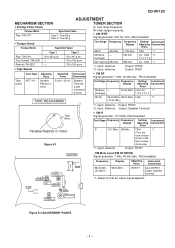
... g Tape 2: Over 80 g fL: Low-range frequency fH: High-range frequency • AM IF/RF Signal generator: 400 Hz, 30%, AM modulated • Torque Check Torque Meter Specified Value Test Stage Frequency Frequency Setting/ Instrument Display Adjusting Connection Parts Play: TW-2111 Fast forward: TW-2231 Rewind: TW-2231 • Tape Speed Tape 1 30 to 180 g.cm AM IF 450 kHz AM Band - Coverage AM Tracking 990 kHz *1. Input: Antenna *2. Input: Antenna Output...
... g Tape 2: Over 80 g fL: Low-range frequency fH: High-range frequency • AM IF/RF Signal generator: 400 Hz, 30%, AM modulated • Torque Check Torque Meter Specified Value Test Stage Frequency Frequency Setting/ Instrument Display Adjusting Connection Parts Play: TW-2111 Fast forward: TW-2231 Rewind: TW-2231 • Tape Speed Tape 1 30 to 180 g.cm AM IF 450 kHz AM Band - Coverage AM Tracking 990 kHz *1. Input: Antenna *2. Input: Antenna Output...
Service Manual
Page 10
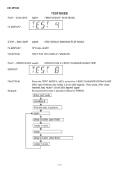
... open finished, tray rotate 1 circle (360 degree). Then close, After close finish rotate 1 circle - 10 - CD-XP120 PLAY + DISC SKIP test04 TEST MODE TIMER ON/OFF TEST MODE FL DISPLAY: STOP + DISC SKIP test05 VFD DISPLAY WINDOW TEST MODE FL DISPLAY: VFD ALL LIGHT FUNCTION: TEST THE VFD DISPLAY WINDOW PLAY + OPEN/CLOSE test08 DISPLAY: OPEN/CLOSE & 3 DISC CHANGER AGING TEST FUNCTION: Request: Enter the TEST MODE 8, MCU control the 3 DISC CHANGER OPEN/CLOSE. Every period include 4 operation.
... open finished, tray rotate 1 circle (360 degree). Then close, After close finish rotate 1 circle - 10 - CD-XP120 PLAY + DISC SKIP test04 TEST MODE TIMER ON/OFF TEST MODE FL DISPLAY: STOP + DISC SKIP test05 VFD DISPLAY WINDOW TEST MODE FL DISPLAY: VFD ALL LIGHT FUNCTION: TEST THE VFD DISPLAY WINDOW PLAY + OPEN/CLOSE test08 DISPLAY: OPEN/CLOSE & 3 DISC CHANGER AGING TEST FUNCTION: Request: Enter the TEST MODE 8, MCU control the 3 DISC CHANGER OPEN/CLOSE. Every period include 4 operation.
Service Manual
Page 11
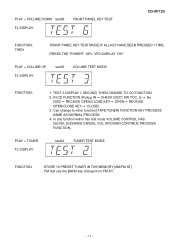
PLAY + VOLUME DOWN test06 FL DISPLAY: FRONT PANEL KEY TEST CD-XP120 FUNCTION: THEN FRONT PANEL KEY TEST MODE,IF ALL KEY HAVE BEEN PRESSED 1 TIME, PRESS THE "POWER" KEY, VFD DISPLAY "OK". TEST 3 DISPLAY 1 SECOND. In any function within this test mode VOLUME CONTROL HAS 3LEVEL [0/23/MAX] CANCEL VOL UP/DOWN CONTINUE PROCESS FUNCTION. test02 TUNER TEST MODE FUNCTION STORE 10 PRESET TUNER IN THE MEMORY [AM/FM ST] FM test use the BAND key change to other function [TAPE/TUNER] FUNCTION KEY PROCESS...
PLAY + VOLUME DOWN test06 FL DISPLAY: FRONT PANEL KEY TEST CD-XP120 FUNCTION: THEN FRONT PANEL KEY TEST MODE,IF ALL KEY HAVE BEEN PRESSED 1 TIME, PRESS THE "POWER" KEY, VFD DISPLAY "OK". TEST 3 DISPLAY 1 SECOND. In any function within this test mode VOLUME CONTROL HAS 3LEVEL [0/23/MAX] CANCEL VOL UP/DOWN CONTINUE PROCESS FUNCTION. test02 TUNER TEST MODE FUNCTION STORE 10 PRESET TUNER IN THE MEMORY [AM/FM ST] FM test use the BAND key change to other function [TAPE/TUNER] FUNCTION KEY PROCESS...
Service Manual
Page 14
... A, E TAPE L 10 R 15 TUNER L 11 R 14 CD L 12 R 13 +B4 23 DI 1 CE 2 IC601 CL 24 LC75341M 21 R AUDIO PROCESSOR 4 L 7 8 17 18 3 Q203 Q204 SYSTEM MUTE BIAS Q801 OSC L801 SW801 H +B4 Figure 14 BLOCK DIAGRAM (3/4) - 14 - TAPE 1 L-CH R-CH RECORD/ PLAYBACK HEAD SW801 B, C, D, F, G AC BIAS ERASE HEAD IC801 AN7345K PLAYBACK AND RECORD /PLAYBACK AMP. CD-XP120 FM ANTENNA AM...
... A, E TAPE L 10 R 15 TUNER L 11 R 14 CD L 12 R 13 +B4 23 DI 1 CE 2 IC601 CL 24 LC75341M 21 R AUDIO PROCESSOR 4 L 7 8 17 18 3 Q203 Q204 SYSTEM MUTE BIAS Q801 OSC L801 SW801 H +B4 Figure 14 BLOCK DIAGRAM (3/4) - 14 - TAPE 1 L-CH R-CH RECORD/ PLAYBACK HEAD SW801 B, C, D, F, G AC BIAS ERASE HEAD IC801 AN7345K PLAYBACK AND RECORD /PLAYBACK AMP. CD-XP120 FM ANTENNA AM...
Service Manual
Page 15
...15A/125V D112~D115 F103 1.6A/125V AC POWER SUPPLY CORD AC 120 V,60 Hz 6.2 V +B6 Q105,Q106 VOLTAGE REGULATOR -30 V -B2 Q101 VOLTAGE REGULATOR T101 POWER TRANSFORMER Figure 15 BLOCK DIAGRAM (4/4) - 15 - CD-XP120 +B4 FL701 FL DISPLAY 1 2 3 ~10 18 ~ 29 30 ...31 32 33 Q203 Q204 SYSTEM MUTE CNP702 FROM CD 1 SECTION 2 CNS702 3 4 5 6 VF2 VF1 15 26 30 37 SW701 ~ ~ +B4 52 51 46 VDD IC701 SC16312 SYSTEM MICROCOMPUTER VDD VEE DIN CLK STB 689 14 27 +B2 -B2 L8 IC201 R 13 LM1876TF POWER AMP...
...15A/125V D112~D115 F103 1.6A/125V AC POWER SUPPLY CORD AC 120 V,60 Hz 6.2 V +B6 Q105,Q106 VOLTAGE REGULATOR -30 V -B2 Q101 VOLTAGE REGULATOR T101 POWER TRANSFORMER Figure 15 BLOCK DIAGRAM (4/4) - 15 - CD-XP120 +B4 FL701 FL DISPLAY 1 2 3 ~10 18 ~ 29 30 ...31 32 33 Q203 Q204 SYSTEM MUTE CNP702 FROM CD 1 SECTION 2 CNS702 3 4 5 6 VF2 VF1 15 26 30 37 SW701 ~ ~ +B4 52 51 46 VDD IC701 SC16312 SYSTEM MICROCOMPUTER VDD VEE DIN CLK STB 689 14 27 +B2 -B2 L8 IC201 R 13 LM1876TF POWER AMP...
Service Manual
Page 16
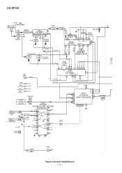
...TUNER SECTION 5 CE DI C 6 A_12V 7 D_GND R129 10 A 12V +B 8 TUN_L 9 TUN_R 10 A_GND 11 A_GND C141 100/16 C142 0.022 +B +B +B AC POWER SUPPLY CORD D C117 2200/35 +B SO101 AC INLET AC 120 V, 60 Hz T101 POWER...FROM CD SERVO PWB CNS105 1 2 3 4 5 6 7 8 9 10 CNP105 P23 9 - D FROM CD SERVO PWB CNS103 3 2 1 CNP103 +B 1 SD 2 FM ST DO +B 3 +B 4 CL P21 12 - G FROM DISPLAY PWB H • NOTES ON SCHEMATIC DIAGRAM can be found on page 34. 1 2 3 4 5 6 Figure 16 SCHEMATIC DIAGRAM (1/10) - 16 - CD-XP120 A FM SIGNAL PLAYBACK SIGNAL RECORD SIGNAL B CD SIGNAL P23...
...TUNER SECTION 5 CE DI C 6 A_12V 7 D_GND R129 10 A 12V +B 8 TUN_L 9 TUN_R 10 A_GND 11 A_GND C141 100/16 C142 0.022 +B +B +B AC POWER SUPPLY CORD D C117 2200/35 +B SO101 AC INLET AC 120 V, 60 Hz T101 POWER...FROM CD SERVO PWB CNS105 1 2 3 4 5 6 7 8 9 10 CNP105 P23 9 - D FROM CD SERVO PWB CNS103 3 2 1 CNP103 +B 1 SD 2 FM ST DO +B 3 +B 4 CL P21 12 - G FROM DISPLAY PWB H • NOTES ON SCHEMATIC DIAGRAM can be found on page 34. 1 2 3 4 5 6 Figure 16 SCHEMATIC DIAGRAM (1/10) - 16 - CD-XP120 A FM SIGNAL PLAYBACK SIGNAL RECORD SIGNAL B CD SIGNAL P23...
Service Manual
Page 17
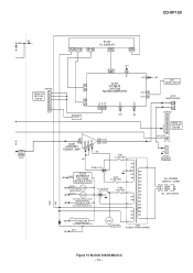
...AUDIO PROCESSOR 13 14 15 16 17 18 19 20 21 22 23 24 C610 2.2/50 C614 0.1(ML) C623 0.1 C617 33/16 CD R C601 R605 1K 10/16 C608 4.7/50 +B R607 1K R609 1K TUN R C602 TAPE...POWER AMP. R-ch + CNP108 CNS108 L IN 5 5 L OUT A_GND 4 3 4 3 R OUT R IN 2 1 2 1 L103 10 µH R128 390 BI108 5 L IN 4 L OUT 3 A_GND 2 R OUT 1 R IN R127 390 JK101 HEADPHONES HEADPHONES PWB-A4 MAIN PWB-A1(1/3) 7 8 9 10 11 12 Figure 17 SCHEMATIC DIAGRAM... + - L-ch SO102 SPEAKER TERMINAL - CD-XP120 B CNP103 M_10V TAPE_DET A_GND M_GND +10V REC L REC R TAPE R TAPE L CHANEL_SW P19 12 -
...AUDIO PROCESSOR 13 14 15 16 17 18 19 20 21 22 23 24 C610 2.2/50 C614 0.1(ML) C623 0.1 C617 33/16 CD R C601 R605 1K 10/16 C608 4.7/50 +B R607 1K R609 1K TUN R C602 TAPE...POWER AMP. R-ch + CNP108 CNS108 L IN 5 5 L OUT A_GND 4 3 4 3 R OUT R IN 2 1 2 1 L103 10 µH R128 390 BI108 5 L IN 4 L OUT 3 A_GND 2 R OUT 1 R IN R127 390 JK101 HEADPHONES HEADPHONES PWB-A4 MAIN PWB-A1(1/3) 7 8 9 10 11 12 Figure 17 SCHEMATIC DIAGRAM... + - L-ch SO102 SPEAKER TERMINAL - CD-XP120 B CNP103 M_10V TAPE_DET A_GND M_GND +10V REC L REC R TAPE R TAPE L CHANEL_SW P19 12 -
Service Manual
Page 24
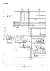
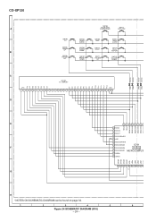
CD-XP120 A B SW702 CD SW703 TUNING UP SW704 PRESET UP SW705 TUNER (BAND) SW706 TUNING DOWN SW707 PRESET DOWN SW708 EQUALIZER/ X-BASS/DEMO SW712 DISC SKIP SW709 TAPE SW710 STOP SW711 VOLUME UP SW713 OPEN/ CLOSE SW714 PLAY/ REPEAT SW715 VOLUME DOWN C VFD701 FL DISPLAY G8 G7 G6 G5 G4 G3 G2 G1 P1 P2 P3 P4 P5 P6 P7 P8 P9 P10 P11 P12 P13 P14 VF1... 33 GRID5 GRID4 GRID3 GRID2 GRID1 5V VDD LED4 LED3 LED2 LED1 GND 34 35 36 37 38 39 40 41 42 4 G H • NOTES ON SCHEMATIC DIAGRAM can be found on page 34. 1 2 3 4 5 6 Figure 24...
CD-XP120 A B SW702 CD SW703 TUNING UP SW704 PRESET UP SW705 TUNER (BAND) SW706 TUNING DOWN SW707 PRESET DOWN SW708 EQUALIZER/ X-BASS/DEMO SW712 DISC SKIP SW709 TAPE SW710 STOP SW711 VOLUME UP SW713 OPEN/ CLOSE SW714 PLAY/ REPEAT SW715 VOLUME DOWN C VFD701 FL DISPLAY G8 G7 G6 G5 G4 G3 G2 G1 P1 P2 P3 P4 P5 P6 P7 P8 P9 P10 P11 P12 P13 P14 VF1... 33 GRID5 GRID4 GRID3 GRID2 GRID1 5V VDD LED4 LED3 LED2 LED1 GND 34 35 36 37 38 39 40 41 42 4 G H • NOTES ON SCHEMATIC DIAGRAM can be found on page 34. 1 2 3 4 5 6 Figure 24...
Service Manual
Page 34
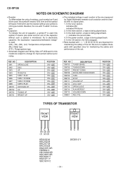
... Y CD-XP120 NOTES ON SCHEMATIC DIAGRAM • Resistor: To differentiate the units of resistors, such symbol as K and M are used : this model are important for maintaining the safety and performance of the set . Besides, the one measured by Digital Multimeter between such a section and the chas- In the tuner section, indicates AM indicates FM stereo 2. In the deck section, a tape is being played...
... Y CD-XP120 NOTES ON SCHEMATIC DIAGRAM • Resistor: To differentiate the units of resistors, such symbol as K and M are used : this model are important for maintaining the safety and performance of the set . Besides, the one measured by Digital Multimeter between such a section and the chas- In the tuner section, indicates AM indicates FM stereo 2. In the deck section, a tape is being played...
Service Manual
Page 36
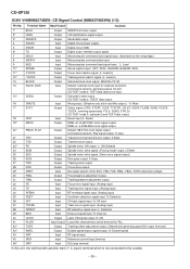
.... CD-TEXT mode 2: TEXT data read clock input. 15* SUBQ Output Subcode Q data output. In this unit, the terminal with general purpose DA output terminal.) 43* WVEL Output Double-speed status signal output. Default: 88.2 kHz clock signal output. H: Off track Track cross signal input. (Analog input) 38 /RFDET 39 BDO Input Input RF detection signal input. H: ON 41 PLLF2 Input/Output Loop filter characteristic switch terminal for subcode Q resistor. CD-XP120 IC401 VHiMN6627482W: CD Signal Control (MN6627482WA...
.... CD-TEXT mode 2: TEXT data read clock input. 15* SUBQ Output Subcode Q data output. In this unit, the terminal with general purpose DA output terminal.) 43* WVEL Output Double-speed status signal output. Default: 88.2 kHz clock signal output. H: Off track Track cross signal input. (Analog input) 38 /RFDET 39 BDO Input Input RF detection signal input. H: ON 41 PLLF2 Input/Output Loop filter characteristic switch terminal for subcode Q resistor. CD-XP120 IC401 VHiMN6627482W: CD Signal Control (MN6627482WA...
Service Manual
Page 41
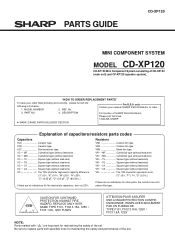
... • • MN Cylindrical type (without lead wire) VC • • TV Square type (without lead wire) VC • • TQ Square type (without lead wire) VC • • CY Square type (without lead wire) VC • • CZ Square type (without lead wire) VR J .. No. Be sure to order. 3. MODEL NUMBER 2. PARTS GUIDE CD-XP120 MINI COMPONENT SYSTEM MODEL CD-XP120 CD-XP120 Mini Component System consisting of the set .
... • • MN Cylindrical type (without lead wire) VC • • TV Square type (without lead wire) VC • • TQ Square type (without lead wire) VC • • CY Square type (without lead wire) VC • • CZ Square type (without lead wire) VR J .. No. Be sure to order. 3. MODEL NUMBER 2. PARTS GUIDE CD-XP120 MINI COMPONENT SYSTEM MODEL CD-XP120 CD-XP120 Mini Component System consisting of the set .
Service Manual
Page 45
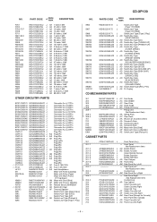
... Switch,Key Type [TUNER (BAND)] J AD Switch,Key Type [TUNING DOWN] J AD Switch,Key Type [PRESET DOWN] J AD Switch,Key Type [EQUALIZER/X-BASS/DEMO] J AD Switch,Key Type [TAPE] J AD Switch,Key Type [STOP] J AD Switch,Key Type [VOLUME UP] J AD Switch,Key Type [DISK SKIP] J AD Switch,Key Type [OPEN/CLOSE] J AD Switch,Key Type [PLAY/REPEAT] J AD Switch,Key Type [VOLUME DOWN] J AD Switch,Slide Type [REC./P.B.] J AX FL Display CD MECHANISM PARTS...
... Switch,Key Type [TUNER (BAND)] J AD Switch,Key Type [TUNING DOWN] J AD Switch,Key Type [PRESET DOWN] J AD Switch,Key Type [EQUALIZER/X-BASS/DEMO] J AD Switch,Key Type [TAPE] J AD Switch,Key Type [STOP] J AD Switch,Key Type [VOLUME UP] J AD Switch,Key Type [DISK SKIP] J AD Switch,Key Type [OPEN/CLOSE] J AD Switch,Key Type [PLAY/REPEAT] J AD Switch,Key Type [VOLUME DOWN] J AD Switch,Slide Type [REC./P.B.] J AX FL Display CD MECHANISM PARTS...
Service Manual
Page 46
...] SSAKA0002SJZZ J AE Polyethylene Bag,Accessories SSAKH0017SJZZ J Polyethylene Bag,Unit ACCESSORIES 1 QACCU0003SJ00 J AH AC Power Supply Cord QANTL0004SJZZ J AM/FM Loop Antenna TCAUZ0024SJZZ J Sheet,Caution TCAUZ0029SJZZ J Sheet,Caution TINSE0080SJZZ J AF Operation Manual [Except for Canada] TINSK0033SJZZ J AG Operation Manual [For Canada] TINSZ0131SJZZ J AD Quick Guide [For U.S.A. PART CODE PRICE RANK DESCRIPTION 215 JBTN-0025SJSA J 216 JBTN-0026SJSA J 217 JBTN-0027SJSA J 218 JBTN...
...] SSAKA0002SJZZ J AE Polyethylene Bag,Accessories SSAKH0017SJZZ J Polyethylene Bag,Unit ACCESSORIES 1 QACCU0003SJ00 J AH AC Power Supply Cord QANTL0004SJZZ J AM/FM Loop Antenna TCAUZ0024SJZZ J Sheet,Caution TCAUZ0029SJZZ J Sheet,Caution TINSE0080SJZZ J AF Operation Manual [Except for Canada] TINSK0033SJZZ J AG Operation Manual [For Canada] TINSZ0131SJZZ J AD Quick Guide [For U.S.A. PART CODE PRICE RANK DESCRIPTION 215 JBTN-0025SJSA J 216 JBTN-0026SJSA J 217 JBTN-0027SJSA J 218 JBTN...

Service Manual
Page 50
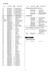
B3CPXP120U TLABR1250SJZZ Label ,Bar Code SPAKC0212SJZZ Packing Case Not Replacement Item CD-XP120 PACKING OF THE SET Setting position of switches and knobs Tape Mechanism STOP UNIT SSAKH0017SJZZ Polyethylene Bag, Unit Top back SPAKA0122SJZZ Packing Add., Left SPAKA0121SJZZ Packing Add., Right SPEAKER ASS'Y CP-XP120 Bottom TLABZ0075SJZZ Label, Feature Tape2 TLABZ0074SJZZ Label, Feature Tape1 A AM/FM Loop Antenna Quick Guide Operation Manual Remote Control Caution Sheet SSAKA0002SJZZ Polyethylene Bag, Accessories B3CPXP120U A TOP FRONT FRONT SIDE OF SPEAKERS - 9 -
B3CPXP120U TLABR1250SJZZ Label ,Bar Code SPAKC0212SJZZ Packing Case Not Replacement Item CD-XP120 PACKING OF THE SET Setting position of switches and knobs Tape Mechanism STOP UNIT SSAKH0017SJZZ Polyethylene Bag, Unit Top back SPAKA0122SJZZ Packing Add., Left SPAKA0121SJZZ Packing Add., Right SPEAKER ASS'Y CP-XP120 Bottom TLABZ0075SJZZ Label, Feature Tape2 TLABZ0074SJZZ Label, Feature Tape1 A AM/FM Loop Antenna Quick Guide Operation Manual Remote Control Caution Sheet SSAKA0002SJZZ Polyethylene Bag, Accessories B3CPXP120U A TOP FRONT FRONT SIDE OF SPEAKERS - 9 -


