

Service Manual
Page 1
.... ONLY) ...2 SPECIFICATIONS ...3 NAMES OF PARTS ...4 OPERATION MANUAL ...6 QUICK GUIDE ...8 DISASSEMBLY ...10 REMOVING AND REINSTALLING THE MAIN PARTS 13 ADJUSTMENT ...14 NOTES ON SCHEMATIC DIAGRAM ...18 TYPES OF TRANSISTOR AND LED ...18 BLOCK DIAGRAM ...19 SCHEMATIC DIAGRAM / WIRING SIDE OF P.W.BOARD 22 VOLTAGE ...39 WAVEFORMS OF CD CIRCUIT ...40 TROUBLESHOOTING ...41 FUNCTION TABLE OF IC ...45 FL DISPLAY ...51 REPLACEMENT PARTS LIST/EXPLODED VIEW PACKING OF THE SET (FOR U.S.A. CD-XP500/CD-XP5500 SERVICE MANUAL No.
.... ONLY) ...2 SPECIFICATIONS ...3 NAMES OF PARTS ...4 OPERATION MANUAL ...6 QUICK GUIDE ...8 DISASSEMBLY ...10 REMOVING AND REINSTALLING THE MAIN PARTS 13 ADJUSTMENT ...14 NOTES ON SCHEMATIC DIAGRAM ...18 TYPES OF TRANSISTOR AND LED ...18 BLOCK DIAGRAM ...19 SCHEMATIC DIAGRAM / WIRING SIDE OF P.W.BOARD 22 VOLTAGE ...39 WAVEFORMS OF CD CIRCUIT ...40 TROUBLESHOOTING ...41 FUNCTION TABLE OF IC ...45 FL DISPLAY ...51 REPLACEMENT PARTS LIST/EXPLODED VIEW PACKING OF THE SET (FOR U.S.A. CD-XP500/CD-XP5500 SERVICE MANUAL No.
Service Manual
Page 2
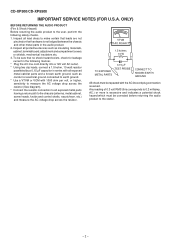
... the user, perform the following manner. * Plug the AC line cord directly into a 120 volt AC outlet. * Using two clip leads, connect a 1.5 kohm, 10 watt resistor paralleled by a 0.15 µF capacitor in series with all protective devices such as conduit or electrical ground connected to earth ground. * Use a VTVM or VOM with the AC line cord plug connection reversed. ONLY) BEFORE RETURNING THE AUDIO...
... the user, perform the following manner. * Plug the AC line cord directly into a 120 volt AC outlet. * Using two clip leads, connect a 1.5 kohm, 10 watt resistor paralleled by a 0.15 µF capacitor in series with all protective devices such as conduit or electrical ground connected to earth ground. * Use a VTVM or VOM with the AC line cord plug connection reversed. ONLY) BEFORE RETURNING THE AUDIO...
Service Manual
Page 3
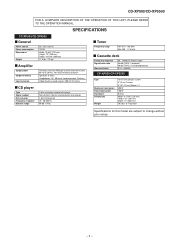
.... (7.9 kg) Amplifier Output power Output terminals Input terminals 150 watts minimum RMS per channel into 6 ohms from 60 Hz to 20 kHz, 10% total harmonic distortion Speakers: 6 ohms Headphones: 16 - 50 ohms (recommended: 32 ohms) Video/Auxiliary (audio signal): 500 mV/47 kohms CD player Type Signal readout D/A converter Frequency response Dynamic range 3-disc multi-play compact disc player Non-contact, 3-beam semiconductor laser pickup 1-bit D/A converter 20 - 20,000 Hz 90 dB (1 kHz) Tuner Frequency range FM: 87...
.... (7.9 kg) Amplifier Output power Output terminals Input terminals 150 watts minimum RMS per channel into 6 ohms from 60 Hz to 20 kHz, 10% total harmonic distortion Speakers: 6 ohms Headphones: 16 - 50 ohms (recommended: 32 ohms) Video/Auxiliary (audio signal): 500 mV/47 kohms CD player Type Signal readout D/A converter Frequency response Dynamic range 3-disc multi-play compact disc player Non-contact, 3-beam semiconductor laser pickup 1-bit D/A converter 20 - 20,000 Hz 90 dB (1 kHz) Tuner Frequency range FM: 87...
Service Manual
Page 4
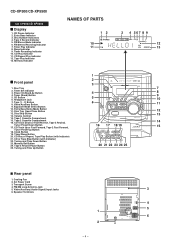
... Bass/Demo Mode Button 11. Disc Skip Button 13 13. Volume Control 14. Timer/Sleep Button 20. AC Power Cord 3. Disc Tray 7 2. Headphone Jack 9 10 7. CD Track Down or Fast Reverse, Tape 2 Rewind, 14 Tuner Preset Down Button 17. CD or Tape Stop Button (with Indicator) 21. FM Stereo Receiving Indicator 7. Timer Recording Indicator 10. Tape 2 Record Pause Button 20 21 22 23 24 25 25. Tape Play Indicator 13. Clock Button 19. Tuning and Time Up Button Rear panel 1. Transport Screw 4. Video/Auxiliary (Audio Signal) Input Jacks 3 6. CD...
... Bass/Demo Mode Button 11. Disc Skip Button 13 13. Volume Control 14. Timer/Sleep Button 20. AC Power Cord 3. Disc Tray 7 2. Headphone Jack 9 10 7. CD Track Down or Fast Reverse, Tape 2 Rewind, 14 Tuner Preset Down Button 17. CD or Tape Stop Button (with Indicator) 21. FM Stereo Receiving Indicator 7. Timer Recording Indicator 10. Tape 2 Record Pause Button 20 21 22 23 24 25 25. Tape Play Indicator 13. Clock Button 19. Tuning and Time Up Button Rear panel 1. Transport Screw 4. Video/Auxiliary (Audio Signal) Input Jacks 3 6. CD...
Service Manual
Page 5
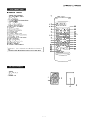
... 15 16 17 18 19 20 21 22 23 24 25 CP-XP500/CP-XP5500 1. CD Clear Button 7. CD Button 12. Power On/Stand-by Button 4 14. Tape 2 Play Button 7 21. Speaker Wire 1 3 2 4 - 5 - Tape 1/Tape 2 Stop Button 2 9. Woofer 4. CD Track Down or Fast Reverse Button 6. Tweeter 2. Other buttons can be operated both on the remote control 12 only. Tuner (Band) Button 13. CD Track Up or Fast Forward Button 6 18. Tape 2 Rewind Button 22. Tuner Preset Up and Down Buttons 20. Disc Number Select Buttons 1 3.
... 15 16 17 18 19 20 21 22 23 24 25 CP-XP500/CP-XP5500 1. CD Clear Button 7. CD Button 12. Power On/Stand-by Button 4 14. Tape 2 Play Button 7 21. Speaker Wire 1 3 2 4 - 5 - Tape 1/Tape 2 Stop Button 2 9. Woofer 4. CD Track Down or Fast Reverse Button 6. Tweeter 2. Other buttons can be operated both on the remote control 12 only. Tuner (Band) Button 13. CD Track Up or Fast Forward Button 6 18. Tape 2 Rewind Button 22. Tuner Preset Up and Down Buttons 20. Disc Number Select Buttons 1 3.
Service Manual
Page 6
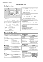
... remote control sensor receive strong light? Are the speaker wires disconnected? When a button is heard. Reset the clock. Sound skipping. If the time display is flashing, step 3 (for selecting the 12-hour or 24-hour display) will flash at the push of the CLOCK button when the AC power supply is possible (about 5 seconds. Do not open the compartment forcibly. CD-XP500/CD-XP5500 Setting the clock OPERATION MANUAL 4 Press the TUNING/TIME( or )button to select...
... remote control sensor receive strong light? Are the speaker wires disconnected? When a button is heard. Reset the clock. Sound skipping. If the time display is flashing, step 3 (for selecting the 12-hour or 24-hour display) will flash at the push of the CLOCK button when the AC power supply is possible (about 5 seconds. Do not open the compartment forcibly. CD-XP500/CD-XP5500 Setting the clock OPERATION MANUAL 4 Press the TUNING/TIME( or )button to select...
Service Manual
Page 7
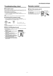
... then turn the power on. CD-XP500/CD-XP5500 Remote control Test of the remote control Point the remote control directly at the remote sensor on ? Make sure that "NO DISC" is equipped with a flat head screwdriver or a coin. - 7 - Does the power turn the power on again. 2 If the unit is operated incorrectly, it may malfunction. Troubleshooting chart If trouble occurs When this unit is displayed. 5 Press the ON/STAND-BY button to...
... then turn the power on. CD-XP500/CD-XP5500 Remote control Test of the remote control Point the remote control directly at the remote sensor on ? Make sure that "NO DISC" is equipped with a flat head screwdriver or a coin. - 7 - Does the power turn the power on again. 2 If the unit is operated incorrectly, it may malfunction. Troubleshooting chart If trouble occurs When this unit is displayed. 5 Press the ON/STAND-BY button to...
Service Manual
Page 10
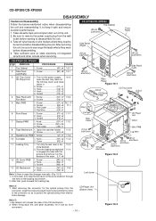
... 1. Be sure to open the disc tray, take out the CD tray cover, and close. (Note 1) 2. Open the cassette holder. .. 11-2 2. Hook K1) x2 11-3 2. Turn on the power supply, .. 10-2 CD Player Unit open the changer manually. (Fig. 10-3) 1. Cover K2) x1 11 Loading Tray 1. After removing the connector for the optical pickup from the wall outlet before...
... 1. Be sure to open the disc tray, take out the CD tray cover, and close. (Note 1) 2. Open the cassette holder. .. 11-2 2. Hook K1) x2 11-3 2. Turn on the power supply, .. 10-2 CD Player Unit open the changer manually. (Fig. 10-3) 1. Cover K2) x1 11 Loading Tray 1. After removing the connector for the optical pickup from the wall outlet before...
Service Manual
Page 14
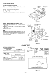
... (See Fig. 14-1) 1. Specified Instrument Value Connection 3,000 ± 30 Hz Speaker Terminal (Load resistance: 6 ohms) TAPE MECHANISM Tape Motor - 14 - CD-XP500/CD-XP5500 CD MECHANISM SECTION Perform steps 1, 2, 3, 10, 11,12 and 13 of connector so as to protect the optical pickup from electrostatic damage. How to remove the shaft (B4) x 1 pc. 3. Bend the hooks (A1) x 6 pcs., to remove the...
... (See Fig. 14-1) 1. Specified Instrument Value Connection 3,000 ± 30 Hz Speaker Terminal (Load resistance: 6 ohms) TAPE MECHANISM Tape Motor - 14 - CD-XP500/CD-XP5500 CD MECHANISM SECTION Perform steps 1, 2, 3, 10, 11,12 and 13 of connector so as to protect the optical pickup from electrostatic damage. How to remove the shaft (B4) x 1 pc. 3. Bend the hooks (A1) x 6 pcs., to remove the...
Service Manual
Page 15
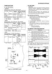
Input: Antenna *2. Input: Antenna Output: Speaker terminal • FM IF Signal generator: 10.7 MHz, FM modulated Test Stage Frequency Frequency Display Setting/ Instrument Adjusting Connection Point IF 10.7 MHz 98 MHz T302 *1 (Turn the core of 'ERCD**' display. 'ER-CD**' display will only be 0 dB.) * Focus gain adjustment * Tracking gain adjustment CD ERROR CODE DESCRIPTION Error Explanation When Pickup set to Disc1 position for 1 st time, 11* "CLAMP SW", "DISC NO SW" and "OPEN/CLOSE" cannot detect 'ON...
Input: Antenna *2. Input: Antenna Output: Speaker terminal • FM IF Signal generator: 10.7 MHz, FM modulated Test Stage Frequency Frequency Display Setting/ Instrument Adjusting Connection Point IF 10.7 MHz 98 MHz T302 *1 (Turn the core of 'ERCD**' display. 'ER-CD**' display will only be 0 dB.) * Focus gain adjustment * Tracking gain adjustment CD ERROR CODE DESCRIPTION Error Explanation When Pickup set to Disc1 position for 1 st time, 11* "CLAMP SW", "DISC NO SW" and "OPEN/CLOSE" cannot detect 'ON...
Service Manual
Page 16
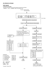
.... + + TEST: CD operation test. CD-XP500/CD-XP5500 TEST MODE • Setting the test mode Any one of test mode can be appoint directly. Laser ON. STOP Sliding the PICKUP with button must only be in STOP mode. CD TEST OPEN/CLOSE operation is input into PLAY key, track number can be set c) Tracking balance d) Tracking Gain f) Focus Gain g) RF level shift = "FOFF_XX" = "TOFF_XX" = "TBAL_XX" = "TGAN_XX" = "FGAN_XX" = "RFLS_XX" VOL - Tracking ON play from that specific point. Function: -CD test mode. -Enter test mode. IL...
.... + + TEST: CD operation test. CD-XP500/CD-XP5500 TEST MODE • Setting the test mode Any one of test mode can be appoint directly. Laser ON. STOP Sliding the PICKUP with button must only be in STOP mode. CD TEST OPEN/CLOSE operation is input into PLAY key, track number can be set c) Tracking balance d) Tracking Gain f) Focus Gain g) RF level shift = "FOFF_XX" = "TOFF_XX" = "TBAL_XX" = "TGAN_XX" = "FGAN_XX" = "RFLS_XX" VOL - Tracking ON play from that specific point. Function: -CD test mode. -Enter test mode. IL...
Service Manual
Page 18
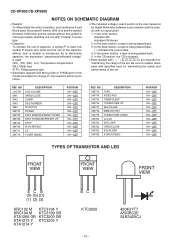
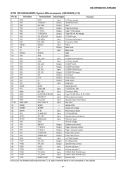
... performance of the set . In the power section, a tape is being played back. ( ) indicates the record state. 4. Be sure to replace these parts with no signal given. 1. NO JOG701 SW1 SW2 SW3 SW4 SW701 SW702 SW703 SW704 SW705 SW711 SW712 DESCRIPTION JOG VOLUME OPEN/CLOSE CLAMP DISC NUMBER PICKUP IN POWER FAST REWIND/PRESET DOWN FAST FORWARD/PRESET UP STOP PLAY/REPEAT CD TUNER (BAND) POSITION...
... performance of the set . In the power section, a tape is being played back. ( ) indicates the record state. 4. Be sure to replace these parts with no signal given. 1. NO JOG701 SW1 SW2 SW3 SW4 SW701 SW702 SW703 SW704 SW705 SW711 SW712 DESCRIPTION JOG VOLUME OPEN/CLOSE CLAMP DISC NUMBER PICKUP IN POWER FAST REWIND/PRESET DOWN FAST FORWARD/PRESET UP STOP PLAY/REPEAT CD TUNER (BAND) POSITION...
Service Manual
Page 21
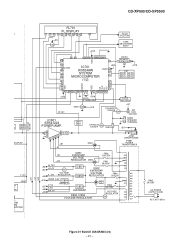
... EC/PLAY T1/T2 BIAS 01 G ME 0 1 AW EM MPUTER ) SYSTEM MUTE VF1 -VF VF2 CD-XP500/CD-XP5500 FL701 FL DISPLAY 1 5 ~ 12 13 14 ~ 19 27 ~ 32 33 ~41 +B9 Q705 45 +B10 TO CD SECTION TAPE MECHANISM ASS...REMOTE 1 SENSOR 3 2 +B10 KEY SW701-SW705 SW711-SW720 SW723-SW726 +B10 SP DET. IC901 STK41223 POWER AMP. L 18 11 L-OUT R 14 7 6 251 8 R-OUT +B1 -B1 +B10 XL701 4.194304 MHz TO CD SECTION RESET Q709 +B10 FAN MOTOR DRIVER Q906 +B7 M4 M FAN MOTOR Q901~ Q904 SP RELAY ON-OFF Q905 RL914 SO901 SPEAKER... Q801 T.F. F805 5A/125V AC POWER SUPPLY CORD AC 120 V, 60 Hz Figure 21 BLOCK...
... EC/PLAY T1/T2 BIAS 01 G ME 0 1 AW EM MPUTER ) SYSTEM MUTE VF1 -VF VF2 CD-XP500/CD-XP5500 FL701 FL DISPLAY 1 5 ~ 12 13 14 ~ 19 27 ~ 32 33 ~41 +B9 Q705 45 +B10 TO CD SECTION TAPE MECHANISM ASS...REMOTE 1 SENSOR 3 2 +B10 KEY SW701-SW705 SW711-SW720 SW723-SW726 +B10 SP DET. IC901 STK41223 POWER AMP. L 18 11 L-OUT R 14 7 6 251 8 R-OUT +B1 -B1 +B10 XL701 4.194304 MHz TO CD SECTION RESET Q709 +B10 FAN MOTOR DRIVER Q906 +B7 M4 M FAN MOTOR Q901~ Q904 SP RELAY ON-OFF Q905 RL914 SO901 SPEAKER... Q801 T.F. F805 5A/125V AC POWER SUPPLY CORD AC 120 V, 60 Hz Figure 21 BLOCK...
Service Manual
Page 41
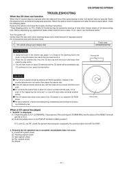
... the bare hand. 1. CD optical pickup Lens cleaner disc Parts code UDSKA0004AFZZ HOW TO USE 1. All rights reserved. Before attempting any excess fluid with the brush side down,then press the play button. 3. Clean the objective lens, and check the playback operation. When this section may be used on car CD players or on computer CD-ROM drives. If the CD cleaner brushes become...
... the bare hand. 1. CD optical pickup Lens cleaner disc Parts code UDSKA0004AFZZ HOW TO USE 1. All rights reserved. Before attempting any excess fluid with the brush side down,then press the play button. 3. Clean the objective lens, and check the playback operation. When this section may be used on car CD players or on computer CD-ROM drives. If the CD cleaner brushes become...
Service Manual
Page 45
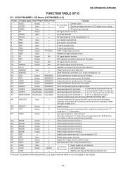
... Input Output - - Left channel output. GND for focus control. CD-XP500/CD-XP5500 FUNCTION TABLE OF IC IC1 VHiLC78645NE1: CD Servo (LC78645NE) (1/2) Pin No. Resistor connection terminal for test. Terminal functions are identified. 32* MONI1 Output L Internal signal monitor terminal 1. 33* MONI2 Output L Internal signal monitor terminal 2. 34* MONI3 Output L Internal signal monitor terminal 3. 35* MONI4 Output L Internal signal monitor terminal 4. 36* MONI5 Output L Internal signal monitor terminal 5. 37 VSS - - Digital system power terminal...
... Input Output - - Left channel output. GND for focus control. CD-XP500/CD-XP5500 FUNCTION TABLE OF IC IC1 VHiLC78645NE1: CD Servo (LC78645NE) (1/2) Pin No. Resistor connection terminal for test. Terminal functions are identified. 32* MONI1 Output L Internal signal monitor terminal 1. 33* MONI2 Output L Internal signal monitor terminal 2. 34* MONI3 Output L Internal signal monitor terminal 3. 35* MONI4 Output L Internal signal monitor terminal 4. 36* MONI5 Output L Internal signal monitor terminal 5. 37 VSS - - Digital system power terminal...
Service Manual
Page 46
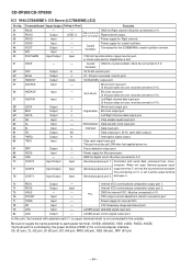
... Input - When not used, General purpose input/ General purpose port 2. Power supply for digital circuit. CD-XP500/CD-XP5500 IC1 VHiLC78645NE1: CD Servo (LC78645NE) (2/2) Pin No. Chip reset signal input port. PDO output current adjustment resistor connection port. 77 VVDD Input - In this port does not use, must be connect to 0 V. 70 CONT3 71 CONT2 72* CONT1 Input/Output Input/Output Input/Output Input Input Input General purpose port 1. Power supply for crystal oscillator. Crystal GND for Right channel...
... Input - When not used, General purpose input/ General purpose port 2. Power supply for digital circuit. CD-XP500/CD-XP5500 IC1 VHiLC78645NE1: CD Servo (LC78645NE) (2/2) Pin No. Chip reset signal input port. PDO output current adjustment resistor connection port. 77 VVDD Input - In this port does not use, must be connect to 0 V. 70 CONT3 71 CONT2 72* CONT1 Input/Output Input/Output Input/Output Input Input Input General purpose port 1. Power supply for crystal oscillator. Crystal GND for Right channel...
Service Manual
Page 49
... Name Input/Output Function 1 VDD VDD Input (+) Power supply. 2 P37 -20dBATT Output -20dB Attenuator. 3* P36 NO USE Output Open 4 P35 T_BIAS Output Tape record bias. 5 P34 T_T1/T2 Output Tape T1/T2 change. 6 P33 T_REC/PLY Output Tape REC/PLAY change. 7 P32 CD_RESOUT Output CD DSP reset. 8 P31 CD WRQ Input CD write read request.. 9 P30 NO USE Input Connect to GND. 28 ANI5 PLAY2/FPA/FPB SW Input Tape F.P A/B SW & PLAY 2 SW. 29 ANI4 PROTECT Input Power abnormal detect. 30 ANI3 LVL_DET Input Speaker output level...
... Name Input/Output Function 1 VDD VDD Input (+) Power supply. 2 P37 -20dBATT Output -20dB Attenuator. 3* P36 NO USE Output Open 4 P35 T_BIAS Output Tape record bias. 5 P34 T_T1/T2 Output Tape T1/T2 change. 6 P33 T_REC/PLY Output Tape REC/PLAY change. 7 P32 CD_RESOUT Output CD DSP reset. 8 P31 CD WRQ Input CD write read request.. 9 P30 NO USE Input Connect to GND. 28 ANI5 PLAY2/FPA/FPB SW Input Tape F.P A/B SW & PLAY 2 SW. 29 ANI4 PROTECT Input Power abnormal detect. 30 ANI3 LVL_DET Input Speaker output level...
Service Manual
Page 53
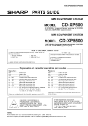
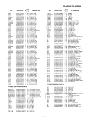
... For location of SHARP Parts Distributor, Please call Toll-Free; 1-800-BE-SHARP MARK: SPARE PARTS-DELIVERY SECTION Explanation of CD-XP5500 (main unit) and CP-XP5500 (speaker system). MINI COMPONENT SYSTEM MODEL CD-XP5500 CD-XP5500 Mini Component System consisting of capacitors/resistors parts codes Capacitors VCC Ceramic type VCK Ceramic type VCT Semiconductor type VC • • MF Cylindrical type (without lead wire) VC •...
... For location of SHARP Parts Distributor, Please call Toll-Free; 1-800-BE-SHARP MARK: SPARE PARTS-DELIVERY SECTION Explanation of CD-XP5500 (main unit) and CP-XP5500 (speaker system). MINI COMPONENT SYSTEM MODEL CD-XP5500 CD-XP5500 Mini Component System consisting of capacitors/resistors parts codes Capacitors VCC Ceramic type VCK Ceramic type VCT Semiconductor type VC • • MF Cylindrical type (without lead wire) VC •...
Service Manual
Page 57
... Switch,Key Type [Tape] AC Switch,Key Type [Video/Aux] AC Switch,Key Type [Timer/Sleep] AC Switch,Key Type [Tuning/Time Up] AC Switch,Key Type [Rec Pause] AC Switch,Key Type [Memory/Set] AC Switch,Key Type [Tuning/Time Down] AC Switch,Key Type [Clock] AC Switch,Key Type [Disc Skip] AC Switch,Key Type [Open/Close] AC Switch,Key Type [Equalizer] AC Switch,Key Type [X-Bass/Demo] AB Holder,Flat Wire CD MECHANISM PARTS...
... Switch,Key Type [Tape] AC Switch,Key Type [Video/Aux] AC Switch,Key Type [Timer/Sleep] AC Switch,Key Type [Tuning/Time Up] AC Switch,Key Type [Rec Pause] AC Switch,Key Type [Memory/Set] AC Switch,Key Type [Tuning/Time Down] AC Switch,Key Type [Clock] AC Switch,Key Type [Disc Skip] AC Switch,Key Type [Open/Close] AC Switch,Key Type [Equalizer] AC Switch,Key Type [X-Bass/Demo] AB Holder,Flat Wire CD MECHANISM PARTS...
Service Manual
Page 64
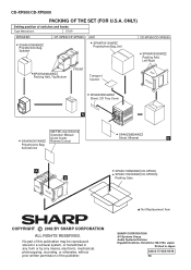
... SPAKA0363AWZZ Packing Add., Left/Right TOP FRONT SPAKZ0891AWZZ BOTTOM Sheet, CD Tray Cover A BOTTOM SSAKA0007AWZZ Polyethylene Bag, Accessories AM/FM Loop Antenna Operation Manual Quick Guide Remote Control SPAKZ0885AWZZ Sheet, Miramat B A B SIDE REAR SPAKC1385AWZZ [CD-XP500] SPAKC1397AWZZ [CD-XP5500] Packing Case Not Replacement Item COPYRIGHT © 2002 BY SHARP CORPORATION ALL RIGHTS RESERVED. No part of this publication may be reproduced, stored in a retrieval...
... SPAKA0363AWZZ Packing Add., Left/Right TOP FRONT SPAKZ0891AWZZ BOTTOM Sheet, CD Tray Cover A BOTTOM SSAKA0007AWZZ Polyethylene Bag, Accessories AM/FM Loop Antenna Operation Manual Quick Guide Remote Control SPAKZ0885AWZZ Sheet, Miramat B A B SIDE REAR SPAKC1385AWZZ [CD-XP500] SPAKC1397AWZZ [CD-XP5500] Packing Case Not Replacement Item COPYRIGHT © 2002 BY SHARP CORPORATION ALL RIGHTS RESERVED. No part of this publication may be reproduced, stored in a retrieval...


