
Service Manual
Page 4
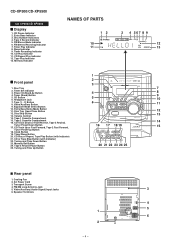
...Screw 4. Tape 2 Record Indicator 5. CD Play Indicator 11. Equalizer Mode Select Button 10. Volume Control 14. CD Track Down or Fast Reverse, Tape 2 Rewind, 14 Tuner Preset Down Button 17. FM/AM Loop Antenna Jack 5. CD-XP500/CD-XP5500 CD-XP500/CD-XP5500 Display 1. Timer Recording Indicator 10... 3. Disc Number Indicators 4. Timer Set Indicator 3. Tape (1 2) Button 6 8. Memory/Set Button 24. FM Stereo Receiving Indicator 7. Tape 2 Cassette Compartment 16. CD Play or Repeat, Tape Play Button (with Indicator) 22. Tape 2 Record Pause Button 20 21 22 23 24...
...Screw 4. Tape 2 Record Indicator 5. CD Play Indicator 11. Equalizer Mode Select Button 10. Volume Control 14. CD Track Down or Fast Reverse, Tape 2 Rewind, 14 Tuner Preset Down Button 17. FM/AM Loop Antenna Jack 5. CD-XP500/CD-XP5500 CD-XP500/CD-XP5500 Display 1. Timer Recording Indicator 10... 3. Disc Number Indicators 4. Timer Set Indicator 3. Tape (1 2) Button 6 8. Memory/Set Button 24. FM Stereo Receiving Indicator 7. Tape 2 Cassette Compartment 16. CD Play or Repeat, Tape Play Button (with Indicator) 22. Tape 2 Record Pause Button 20 21 22 23 24...
Service Manual
Page 17
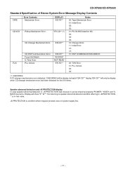
... be display instead of Stereo System Error Message Display Contents TAPE Error Contents Mechanism Error. Speaker abnormal detection and +B PROTECTION display In case speaker abnormal detection or +B PROTECTION had been detected for the 5 th times. CD-XP500/CD-XP5500 Standard Specification of 'ER-CD**' display 'ER-CD**' will only be display when CD changer mechanism error had...
... be display instead of Stereo System Error Message Display Contents TAPE Error Contents Mechanism Error. Speaker abnormal detection and +B PROTECTION display In case speaker abnormal detection or +B PROTECTION had been detected for the 5 th times. CD-XP500/CD-XP5500 Standard Specification of 'ER-CD**' display 'ER-CD**' will only be display when CD changer mechanism error had...
Service Manual
Page 18
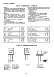
sis with no signal given. 1. In the tuner section, indicates AM indicates FM stereo 2. In the CD section, the CD is microfarad. Besides, the one measured by Digital Multimeter between such a section and the chas- Be sure to replace these parts with specified ones for ...-OFF ON-OFF ON-OFF ON-OFF ON-OFF ON-OFF ON-OFF ON-OFF ON-OFF ON-OFF ON-OFF ON-OFF REF. REF. CD-XP500/CD-XP5500 NOTES ON SCHEMATIC DIAGRAM • Resistor: To differentiate the units of resistors, such symbol as K and M are used : this symbol P means pico-farad and...
sis with no signal given. 1. In the tuner section, indicates AM indicates FM stereo 2. In the CD section, the CD is microfarad. Besides, the one measured by Digital Multimeter between such a section and the chas- Be sure to replace these parts with specified ones for ...-OFF ON-OFF ON-OFF ON-OFF ON-OFF ON-OFF ON-OFF ON-OFF ON-OFF ON-OFF ON-OFF ON-OFF REF. REF. CD-XP500/CD-XP5500 NOTES ON SCHEMATIC DIAGRAM • Resistor: To differentiate the units of resistors, such symbol as K and M are used : this symbol P means pico-farad and...
Service Manual
Page 20
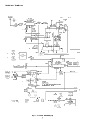
TAPE 2 L-CH P.B. CD-XP500/CD-XP5500 SYSTEM MUTE AM LOOP ANTENNA FM ANTENNA IC301 TA7358AP FM FRONT END FM IF +B6 +B5 ZD351 +B6... IF AM MIX FM RF L312 T301 FM OSC 24 23 21 7 18 16 MPXIN L 14 R 15 12 STEREO AM OSC OUT AM OSC IN AM RF IN OSC BUFF Q302 AM TRACKING T303 T306 AM BAND COVERAGE X352 VT ...B5 23 L9 DI 1 R 16 CE 2 TAPE TUNER L R L R 10 15 11 14 IC601 CLK LC75341 AUDIO PROCESSOR 24 21 R -20dB ATT Q601 Q602 CD L 12 4L R 13 7 8 1718 3 Q603 Q604 TAPE 1 L-CH P.B. REC./P.B. VF1 HEAD R-CH REC. R-CH HEAD AC BIAS ERASE HEAD SWITCHING Q101~ ...
TAPE 2 L-CH P.B. CD-XP500/CD-XP5500 SYSTEM MUTE AM LOOP ANTENNA FM ANTENNA IC301 TA7358AP FM FRONT END FM IF +B6 +B5 ZD351 +B6... IF AM MIX FM RF L312 T301 FM OSC 24 23 21 7 18 16 MPXIN L 14 R 15 12 STEREO AM OSC OUT AM OSC IN AM RF IN OSC BUFF Q302 AM TRACKING T303 T306 AM BAND COVERAGE X352 VT ...B5 23 L9 DI 1 R 16 CE 2 TAPE TUNER L R L R 10 15 11 14 IC601 CLK LC75341 AUDIO PROCESSOR 24 21 R -20dB ATT Q601 Q602 CD L 12 4L R 13 7 8 1718 3 Q603 Q604 TAPE 1 L-CH P.B. REC./P.B. VF1 HEAD R-CH REC. R-CH HEAD AC BIAS ERASE HEAD SWITCHING Q101~ ...
Service Manual
Page 25
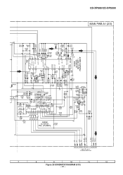
B, C TO MAIN SECTION 7 8 9 10 11 12 Figure 25 SCHEMATIC DIAGRAM (4/10) - 25 - CD-XP500/CD-XP5500 MAIN PWB-A1 (2/3) C362 3.3/50 C361 0.022 +B C342 0.022 R365 10K R358 3.9K TP302 R357 470K C373 0.015 C371 1/50 X351 456 kHz C368 1/... OUT L-CH OUT PHASE (FM/AM) MO/ST VSM AM LOW CUT AM IF IN FM/AM OUT GND SD AM RF IN FM AFC STEREO AM MIX OUT AM OSC OUT FM IF IN AM OSC IN R351 5.6K REG TP301 +B 1 23 4 56 R352 1K T351 13 78 C351 0.022...
B, C TO MAIN SECTION 7 8 9 10 11 12 Figure 25 SCHEMATIC DIAGRAM (4/10) - 25 - CD-XP500/CD-XP5500 MAIN PWB-A1 (2/3) C362 3.3/50 C361 0.022 +B C342 0.022 R365 10K R358 3.9K TP302 R357 470K C373 0.015 C371 1/50 X351 456 kHz C368 1/... OUT L-CH OUT PHASE (FM/AM) MO/ST VSM AM LOW CUT AM IF IN FM/AM OUT GND SD AM RF IN FM AFC STEREO AM MIX OUT AM OSC OUT FM IF IN AM OSC IN R351 5.6K REG TP301 +B 1 23 4 56 R352 1K T351 13 78 C351 0.022...


