

Service Manual
Page 1
...the set. TROUBLE SHOOTING TABLE CHAPTER 7. SAFETY PRECAUTION CHAPTER 1. DIMENSIONS CHAPTER 4. OVERALL WIRING/BLOCK DIAGRAM CHAPTER 9. OPERATION MANUAL CHAPTER 3. REMOVING OF MAJOR PARTS CHAPTER 5. MAJOR IC INFORMATIONS CHAPTER 8. PRINTED WIRING BOARD ASSEMBLIES CHAPTER 10. SCHEMATIC ...published to those specified should be used . SPECIFICATIONS CONTENTS CHAPTER 2. TopPage LC-32D41U/LC-32M41U/LC-40C32U SERVICE MANUAL No. S56T6LC32D41U LCD COLOR TELEVISION LC-32D41U LC-32M41U MODELS LC-40C32U In the interests of the set should be restored to its original condition...
...the set. TROUBLE SHOOTING TABLE CHAPTER 7. SAFETY PRECAUTION CHAPTER 1. DIMENSIONS CHAPTER 4. OVERALL WIRING/BLOCK DIAGRAM CHAPTER 9. OPERATION MANUAL CHAPTER 3. REMOVING OF MAJOR PARTS CHAPTER 5. MAJOR IC INFORMATIONS CHAPTER 8. PRINTED WIRING BOARD ASSEMBLIES CHAPTER 10. SCHEMATIC ...published to those specified should be used . SPECIFICATIONS CONTENTS CHAPTER 2. TopPage LC-32D41U/LC-32M41U/LC-40C32U SERVICE MANUAL No. S56T6LC32D41U LCD COLOR TELEVISION LC-32D41U LC-32M41U MODELS LC-40C32U In the interests of the set should be restored to its original condition...
Service Manual
Page 3
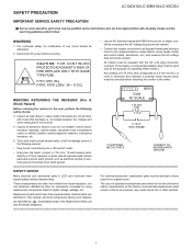
...mA rms AC.) or more is not lodged between the chassis and other hazards. LSCA-32FDE41TU/YLC-P32RME41CU/LAC-U40TC3IO2UN LC-32D41U/LC-32M41U/LC-40C32U Service Manual IMPORTANT SERVICE SAFETY PRECAUTION Service work should be attempted. 2. TO EXPOSED METAL PARTS CONNECT TO KNOWN EARTH GROUND SAFETY...etc. These characteristics are identified in series with all protective devices such as the factory recommended replacement parts shown in this service manual, may create shock, fire or other metal parts in the following safety checks: DVM AC SCALE 1.5k ohm 10W 3. Replacement...
...mA rms AC.) or more is not lodged between the chassis and other hazards. LSCA-32FDE41TU/YLC-P32RME41CU/LAC-U40TC3IO2UN LC-32D41U/LC-32M41U/LC-40C32U Service Manual IMPORTANT SERVICE SAFETY PRECAUTION Service work should be attempted. 2. TO EXPOSED METAL PARTS CONNECT TO KNOWN EARTH GROUND SAFETY...etc. These characteristics are identified in series with all protective devices such as the factory recommended replacement parts shown in this service manual, may create shock, fire or other metal parts in the following safety checks: DVM AC SCALE 1.5k ohm 10W 3. Replacement...
Service Manual
Page 5
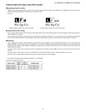
... solder of the soldering bit is alloyed with conventional lead wire solder may cause damage or accident due to turn on the PWBs and service manuals. The LF symbol indicates lead-free solder, and is higher than the lead wire solder by 40 °C, we recommend you to use of tin... our service station or service branch in contact with the lead-free solder, apply lead-free wire solder. PRECAUTIONS FOR USING LEAD-FREE SOLDER LC-32D41U/LC-32M41U/LC-40C32U „Employing lead-free solder • "PWBs" of lead-free solder. As the melting point of lead-free solder (Sn-Ag-Cu) is higher...
... solder of the soldering bit is alloyed with conventional lead wire solder may cause damage or accident due to turn on the PWBs and service manuals. The LF symbol indicates lead-free solder, and is higher than the lead wire solder by 40 °C, we recommend you to use of tin... our service station or service branch in contact with the lead-free solder, apply lead-free wire solder. PRECAUTIONS FOR USING LEAD-FREE SOLDER LC-32D41U/LC-32M41U/LC-40C32U „Employing lead-free solder • "PWBs" of lead-free solder. As the melting point of lead-free solder (Sn-Ag-Cu) is higher...
Service Manual
Page 6
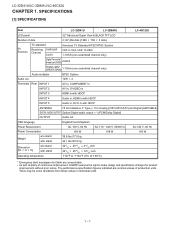
...to make design and specification changes for product improvement without prior notice. LC-32D41U/LC-32M41U/LC-40C32U LCC-H32AD41PU/TLCE-3R2M411U./LSC-4P0CE3C2UIFICATIONS [1] SPECIFICATIONS Service Manual Item LC-32D41U LC-32M41U LC-40C32U LCD panel 32" Advanced Super View & BLACK TFT LCD Number of ...production units. The performance specification figures indicated are unreceivable. As part of policy of continuous improvement, SHARP reserves the right...
...to make design and specification changes for product improvement without prior notice. LC-32D41U/LC-32M41U/LC-40C32U LCC-H32AD41PU/TLCE-3R2M411U./LSC-4P0CE3C2UIFICATIONS [1] SPECIFICATIONS Service Manual Item LC-32D41U LC-32M41U LC-40C32U LCD panel 32" Advanced Super View & BLACK TFT LCD Number of ...production units. The performance specification figures indicated are unreceivable. As part of policy of continuous improvement, SHARP reserves the right...
Service Manual
Page 11
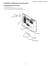
Remove the SD Card Cover. 2. Remove the 4 lock screws and detach the Stand Base Ass'y. 3. LC-32D41U/LC-32M41U/LC-40C32U LCC-H32AD41PU/TLCE-3R2M441U./LRC-4E0CM32OU VING OF MAJOR PARSTeSrvice Manual [1] REMOVING OF MAJOR PARTS 1. Remove the 9 lock screws, 3 lock screws and detach the Rear Cabinet. 1 3 SD Card Cover 3 2 Rear Cabinet Stand Base Ass'y 4 - 1
Remove the SD Card Cover. 2. Remove the 4 lock screws and detach the Stand Base Ass'y. 3. LC-32D41U/LC-32M41U/LC-40C32U LCC-H32AD41PU/TLCE-3R2M441U./LRC-4E0CM32OU VING OF MAJOR PARSTeSrvice Manual [1] REMOVING OF MAJOR PARTS 1. Remove the 9 lock screws, 3 lock screws and detach the Rear Cabinet. 1 3 SD Card Cover 3 2 Rear Cabinet Stand Base Ass'y 4 - 1
Service Manual
Page 16
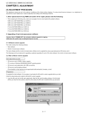
.../sd/download/sd_formatter_e.html) Preparations To upgrade the main software, it is inserted before shipping. Start the SD card formatting software. LC-32D41U/LC-32M41U/LC-40C32U LCC-H32AD41PU/TLCE-3R2M451U./LAC-4D0CJ3U2USTMENT Service Manual [1] ADJUSTMENT PROCEDURE The adjustment values are the procedures for upgrading, explained separately for version upgrade. 1. If a value should become improper...
.../sd/download/sd_formatter_e.html) Preparations To upgrade the main software, it is inserted before shipping. Start the SD card formatting software. LC-32D41U/LC-32M41U/LC-40C32U LCC-H32AD41PU/TLCE-3R2M451U./LAC-4D0CJ3U2USTMENT Service Manual [1] ADJUSTMENT PROCEDURE The adjustment values are the procedures for upgrading, explained separately for version upgrade. 1. If a value should become improper...
Service Manual
Page 32
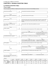
... Are there defective parts on the secondary side short-circuited? NO Does PNL_POW (pin 4 of CN5702) become High (approx. 3.3V)? LC-32D41U/LC-32M41U/LC-40C32U LCC-H32AD41PU/TLCE-3R2M461U./LTC-R40CO32UUBLE SHOOTING TABLSEervice Manual [1] TROUBLE SHOOTING TABLE No power supply (Front LED does not light up) and no power-up even is blown when...
... Are there defective parts on the secondary side short-circuited? NO Does PNL_POW (pin 4 of CN5702) become High (approx. 3.3V)? LC-32D41U/LC-32M41U/LC-40C32U LCC-H32AD41PU/TLCE-3R2M461U./LTC-R40CO32UUBLE SHOOTING TABLSEervice Manual [1] TROUBLE SHOOTING TABLE No power supply (Front LED does not light up) and no power-up even is blown when...
Service Manual
Page 43
... an NTSC video encoder. Using these interfaces, the CPU controls peripheral circuits of the tuner, SD Memory Cards, CableCARDs, etc. LC-32D41U/LC-32M41U/LC-40C32U LCC-H32AD41PU/TLCE-3R2M471U./LMC-4A0CJ32OU R IC INFORMATIONS Service Manual [1] MAJOR IC INFORMATIONS • IC8101 (RH-iXB145WJQZQ) An LSI of a MPEG-2 system decoder that performs back-end processing for...
... an NTSC video encoder. Using these interfaces, the CPU controls peripheral circuits of the tuner, SD Memory Cards, CableCARDs, etc. LC-32D41U/LC-32M41U/LC-40C32U LCC-H32AD41PU/TLCE-3R2M471U./LMC-4A0CJ32OU R IC INFORMATIONS Service Manual [1] MAJOR IC INFORMATIONS • IC8101 (RH-iXB145WJQZQ) An LSI of a MPEG-2 system decoder that performs back-end processing for...
Service Manual
Page 67
... BEFORE REPLACING PARTS. 2) SEMICONDUCTOR HEAT SINKS SHOULD BE REGARDED AS POTENTIAL SHOCK HAZARDS WHEN THE CHASSIS IS OPERATING. LCC-H32AD41PU/TLCE-3R2M411U0/L.C-S40CC3H2UEMATIC DIAGRAM LC-32D41U/LC-32M41U/LC-40C32U Service Manual [1] DESCRIPTION OF SCHEMATIC DIAGRAM 1. BE SURE TO REPLACE THESE PARTS WITH SPECIFIED ONES FOR MAIN- INDICATION OF RESISTOR & CAPACITOR: RESISTOR 1) The unit of...
... BEFORE REPLACING PARTS. 2) SEMICONDUCTOR HEAT SINKS SHOULD BE REGARDED AS POTENTIAL SHOCK HAZARDS WHEN THE CHASSIS IS OPERATING. LCC-H32AD41PU/TLCE-3R2M411U0/L.C-S40CC3H2UEMATIC DIAGRAM LC-32D41U/LC-32M41U/LC-40C32U Service Manual [1] DESCRIPTION OF SCHEMATIC DIAGRAM 1. BE SURE TO REPLACE THESE PARTS WITH SPECIFIED ONES FOR MAIN- INDICATION OF RESISTOR & CAPACITOR: RESISTOR 1) The unit of...
Service Manual
Page 144
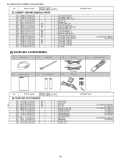
... Clamp X Cable Band X AC Cord X AC Cord X Remote Control Unit X Remote Control Unit X Operation Manual X Operation Manual X Operation Manual - "AAA" Size Battery X Stand Ass'y X Stand Ass'y X Enquete Card X Caution Card DESCRIPTION [LC-32D41U/LC-40C32U] [LC-32M41U] [LC-32D41U/LC-32M41U] [LC-40C32U] [LC-32D41U] [LC-32M41U] [LC-40C32U] [LC-32D41U/LC-32M41U] [LC-40C32U] 26 X3 QACCDA039WJPZ AQ ! PARTS CODE PRICE NEW PART RANK MARK DELIVERY [7] CABINET AND...
... Clamp X Cable Band X AC Cord X AC Cord X Remote Control Unit X Remote Control Unit X Operation Manual X Operation Manual X Operation Manual - "AAA" Size Battery X Stand Ass'y X Stand Ass'y X Enquete Card X Caution Card DESCRIPTION [LC-32D41U/LC-40C32U] [LC-32M41U] [LC-32D41U/LC-32M41U] [LC-40C32U] [LC-32D41U] [LC-32M41U] [LC-40C32U] [LC-32D41U/LC-32M41U] [LC-40C32U] 26 X3 QACCDA039WJPZ AQ ! PARTS CODE PRICE NEW PART RANK MARK DELIVERY [7] CABINET AND...


