
Operater's Manual
Page 12
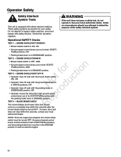
... START/PARK position with safety devices. Do not attempt to start the engine. 12 Test 2 - fo tio Test 3 - If mower drive belt does not stop within five seconds, contact your local authorized dealer. Operational SAFETY Checks Test 1 - Blade Brake Check R The mower blades and mower ...drive belt should SHUT OFF if: • Operator rises off seat with the mower blade switch t c ON, OR o u • Operator rises off ...
... START/PARK position with safety devices. Do not attempt to start the engine. 12 Test 2 - fo tio Test 3 - If mower drive belt does not stop within five seconds, contact your local authorized dealer. Operational SAFETY Checks Test 1 - Blade Brake Check R The mower blades and mower ...drive belt should SHUT OFF if: • Operator rises off seat with the mower blade switch t c ON, OR o u • Operator rises off ...

Operater's Manual
Page 22
..." Deck • brake linkage • mower deck height adjustment linkage • ground speed control linkage Generally, all greases are compatible. Keep oil and grease off belts and pulleys. Maintenance Lubrication Lubricate the unit at the locations shown in Figures 13 through 18 as well as the following lubrication points. Grease: •...
..." Deck • brake linkage • mower deck height adjustment linkage • ground speed control linkage Generally, all greases are compatible. Keep oil and grease off belts and pulleys. Maintenance Lubrication Lubricate the unit at the locations shown in Figures 13 through 18 as well as the following lubrication points. Grease: •...
Operater's Manual
Page 26
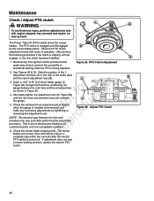
... equal amount of the 3 adjustment windows (A) in Figure 25. 4. e 6. The Power Take Off (PTO) clutch drives the mower blades. o 5. The mower blades and mower drive belt should come to dimensional variations on level ground. See Figures 24 & 25. Insert a .012"-.015" (2,5-4mm) feeler gauge (C, Figure 25) through each window, positioning the...
... equal amount of the 3 adjustment windows (A) in Figure 25. 4. e 6. The Power Take Off (PTO) clutch drives the mower blades. o 5. The mower blades and mower drive belt should come to dimensional variations on level ground. See Figures 24 & 25. Insert a .012"-.015" (2,5-4mm) feeler gauge (C, Figure 25) through each window, positioning the...
Operater's Manual
Page 35
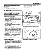
...position, engage the parking brake, turn the ignition switch to STOP, and remove key before attempting to RUN without fo tio starting the engine. 4. Mower Belt Routing - 33" Decks 35 Place 4x4 wood blocks (D, Figure 43) under the front o and rear lip of the rider. Remove the hair pin...fully lower the N d mower so that is no longer resting on the 4x4 wood blocks. 8. Release mower belt tension, and install the belt as a concrete floor. Turn the ignition switch to release belt tension. p 10. Secure with hair pin clips (A). 3. Use the mower cutting height switch to RUN without ...
...position, engage the parking brake, turn the ignition switch to STOP, and remove key before attempting to RUN without fo tio starting the engine. 4. Mower Belt Routing - 33" Decks 35 Place 4x4 wood blocks (D, Figure 43) under the front o and rear lip of the rider. Remove the hair pin...fully lower the N d mower so that is no longer resting on the 4x4 wood blocks. 8. Release mower belt tension, and install the belt as a concrete floor. Turn the ignition switch to release belt tension. p 10. Secure with hair pin clips (A). 3. Use the mower cutting height switch to RUN without ...
Operater's Manual
Page 36
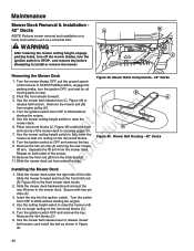
...lever to raise the mower deck. Turn the ignition switch from the mower deck. Use the mower cutting height switch to release mower belt tension, and install the belt as a concrete floor. Place 4x4 wood blocks (C, Figure 45) under the front o and rear lip of the mower. u ...& Installation - 42" Decks A NOTE: Perform mower removal and installation on both sides of the mower deck to RUN without starting the engine. 5. Mower Belt Routing - 42" Decks R Installing the Mower Deck A 1. Separate the lift arm from OFF to securely support it resting on the 4x4 wood blocks (C)....
...lever to raise the mower deck. Turn the ignition switch from the mower deck. Use the mower cutting height switch to release mower belt tension, and install the belt as a concrete floor. Place 4x4 wood blocks (C, Figure 45) under the front o and rear lip of the mower. u ...& Installation - 42" Decks A NOTE: Perform mower removal and installation on both sides of the mower deck to RUN without starting the engine. 5. Mower Belt Routing - 42" Decks R Installing the Mower Deck A 1. Separate the lift arm from OFF to securely support it resting on the 4x4 wood blocks (C)....

Operater's Manual
Page 37
... START/PARK, and set the parking brake lever to ENGAGE. Remove the key. Pull the idler pulley (C, Figure 47) to remove the mower deck. 4. Mower Belt Replacement WARNING Before inspecting or servicing the mower, turn the mower blades OFF, turn off the engine, set the ground speed control levers to START...: The left rear threaded rod must be removed from the mower in Figure 47. Use the idler pulley arm (C, Figure 48) to completely remove the r n belt. Refer to stop. Remove ignition key, then disconnect the spark plug wire and fasten it away from the e PTO pulley (B).
... START/PARK, and set the parking brake lever to ENGAGE. Remove the key. Pull the idler pulley (C, Figure 47) to remove the mower deck. 4. Mower Belt Replacement WARNING Before inspecting or servicing the mower, turn the mower blades OFF, turn off the engine, set the ground speed control levers to START...: The left rear threaded rod must be removed from the mower in Figure 47. Use the idler pulley arm (C, Figure 48) to completely remove the r n belt. Refer to stop. Remove ignition key, then disconnect the spark plug wire and fasten it away from the e PTO pulley (B).
Operater's Manual
Page 40
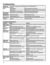
...not properly slips or fails to arbors. Troubleshooting Engine runs, Transmission release levers in PUSH but rider will not hold. Drive belt slips. Improper tire inflation. Contact your local authorized dealer. Check and tighten any loose connections. Always set too low. ...drive. Parking brake is loose. Mower not leveled properly. See Maintenance Section. Excessive Blade mounting nuts are bent. Clean or replace belt as necessary. Mower cut grass. t c rough looking. Remove mower deck and clean underside. PTO clutch out of mower deck dirty...
...not properly slips or fails to arbors. Troubleshooting Engine runs, Transmission release levers in PUSH but rider will not hold. Drive belt slips. Improper tire inflation. Contact your local authorized dealer. Check and tighten any loose connections. Always set too low. ...drive. Parking brake is loose. Mower not leveled properly. See Maintenance Section. Excessive Blade mounting nuts are bent. Clean or replace belt as necessary. Mower cut grass. t c rough looking. Remove mower deck and clean underside. PTO clutch out of mower deck dirty...
Operater's Manual
Page 41
... implied warranties are handled routinely, but sometimes requests for the period of N d the initial purchase date at www. Maintenance and wear items such as filters, belts, cutting blades, and brake pads (except engine brake pads) are limited to one year from state to state or country to country.** Warranty PerioD item...
... implied warranties are handled routinely, but sometimes requests for the period of N d the initial purchase date at www. Maintenance and wear items such as filters, belts, cutting blades, and brake pads (except engine brake pads) are limited to one year from state to state or country to country.** Warranty PerioD item...
Operater's Manual
Page 42
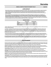
... in accordance with the Operating & Maintenance Instructions. Warranted Emissions Parts The warranty on emissions-related parts is as follows: Coverage under warranty will be hoses, belts, connectors, sensors, and other associated components. Consequential Coverage Coverage shall extend to the owner. The engine emissions label will be warranted for the remaining warranty...
... in accordance with the Operating & Maintenance Instructions. Warranted Emissions Parts The warranty on emissions-related parts is as follows: Coverage under warranty will be hoses, belts, connectors, sensors, and other associated components. Consequential Coverage Coverage shall extend to the owner. The engine emissions label will be warranted for the remaining warranty...
Parts Manual
Page 11
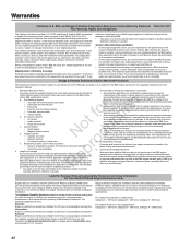
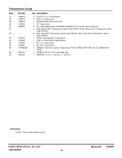
...2A7C-1DPX) 1 SUPPORT, Transmission Rear - x 1.50 O.D. Thread .625 O.D., Black Footnotes: NOTE: * Part number printed on belt. X .06 Thick) Black 1 NUT, 5/16-18 Hex Flange Lock Large, Black 1 * V-BELT, Transmission Drive (HA Sect. 54.40 Effective Length) 3 NUT, 3/8-16 Hex Flange Lock Two Way, Black 3 WASHER, .41...GR5, Black 4 WASHER, 5/16" Flat (.341 I .D. Black 8 NUT, 1/2-20, (for .188 Dia. x 1.50 O.D. HYDRO DRIVE ZTR 33", 42" & 50" 150Z SERIES 11 Manual No. 7006269 x 0.270 Long Heat Treated 2 NUT, 5/16-18 Hex Keps Conical Washer, Black 1 ROD, Control, LH (.500 Dia. x .12 Flat...
...2A7C-1DPX) 1 SUPPORT, Transmission Rear - x 1.50 O.D. Thread .625 O.D., Black Footnotes: NOTE: * Part number printed on belt. X .06 Thick) Black 1 NUT, 5/16-18 Hex Flange Lock Large, Black 1 * V-BELT, Transmission Drive (HA Sect. 54.40 Effective Length) 3 NUT, 3/8-16 Hex Flange Lock Two Way, Black 3 WASHER, .41...GR5, Black 4 WASHER, 5/16" Flat (.341 I .D. Black 8 NUT, 1/2-20, (for .188 Dia. x 1.50 O.D. HYDRO DRIVE ZTR 33", 42" & 50" 150Z SERIES 11 Manual No. 7006269 x 0.270 Long Heat Treated 2 NUT, 5/16-18 Hex Keps Conical Washer, Black 1 ROD, Control, LH (.500 Dia. x .12 Flat...
Parts Manual
Page 13
...) (HUB, Wheel, EZT Transmission (Hydro- Gear #70314)) 2 NUT, Axle, EZT Transmission (Hydro-Gear #51901) (NUT, Axle, EZT Transmission (Hydro- HYDRO DRIVE ZTR 33", 42" & 50" 150Z SERIES 13 Manual No. 7006269 Control Arm 1 SPRING, Extension (Used on...
...) (HUB, Wheel, EZT Transmission (Hydro- Gear #70314)) 2 NUT, Axle, EZT Transmission (Hydro-Gear #51901) (NUT, Axle, EZT Transmission (Hydro- HYDRO DRIVE ZTR 33", 42" & 50" 150Z SERIES 13 Manual No. 7006269 Control Arm 1 SPRING, Extension (Used on...
Parts Manual
Page 33
..., Belt/Blade ZT 1 DECAL, Hot Surfaces 1 DECAL, SNAPPER-RH Stripe & Logo ZT 1 DECAL, New SNAPPER Stripe, RH 1 DECAL, SNAPPER-LH Stripe & Logo ZT 1 DECAL, New SNAPPER Stripe, LH 1 DECAL, Height-Of-Cut 1 DECAL, Height-Of-Cut, Without Best Cut (CE/Export) 1 DECAL, 150Z 18.5HP SNAPPER ZT 1 DECAL, 150Z 20HP SNAPPER ZT (CE/Export) 1 DECAL, 150Z 21HP SNAPPER ZT 1 DECAL, 150Z 26HP SNAPPER...
..., Belt/Blade ZT 1 DECAL, Hot Surfaces 1 DECAL, SNAPPER-RH Stripe & Logo ZT 1 DECAL, New SNAPPER Stripe, RH 1 DECAL, SNAPPER-LH Stripe & Logo ZT 1 DECAL, New SNAPPER Stripe, LH 1 DECAL, Height-Of-Cut 1 DECAL, Height-Of-Cut, Without Best Cut (CE/Export) 1 DECAL, 150Z 18.5HP SNAPPER ZT 1 DECAL, 150Z 20HP SNAPPER ZT (CE/Export) 1 DECAL, 150Z 21HP SNAPPER ZT 1 DECAL, 150Z 26HP SNAPPER...
Parts Manual
Page 41
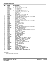
...GUARD, Idler Pulley, 33" ZT 2 SCREW, 5/16-18 x 3/4" Hex Washer Self-Tap Footnotes: NOTE: * Part number printed on belt. RH 1 RAIL, 33" Side - HYDRO DRIVE ZTR 33", 42" & 50" 150Z SERIES 41 Manual No. 7006269 x .750 O.D. LH 16 BOLT, 5/16-18 x 5/8" Hex Flange Lock 3 SCREW, 3/8-24 x 3/4"... Chute 1 BRACKET, Mower Front 3 BOLT, 5/16-18 x 5/8" Round Head Short Square Neck, GR5 1 BRACKET, Anti-Scalp Front Adjust 8 NUT, 3/8-16 Hex Flange Lock 1 * BELT, 33" Deck Drive (HB Section, 74.97 Effective Length) 1 NUT, 3/4-16 Hex Jam 2 WASHER, .77 x 1.5 x .06 Flat 1 PULLEY, 33" ZT Spindle 2 RETAINING...
...GUARD, Idler Pulley, 33" ZT 2 SCREW, 5/16-18 x 3/4" Hex Washer Self-Tap Footnotes: NOTE: * Part number printed on belt. RH 1 RAIL, 33" Side - HYDRO DRIVE ZTR 33", 42" & 50" 150Z SERIES 41 Manual No. 7006269 x .750 O.D. LH 16 BOLT, 5/16-18 x 5/8" Hex Flange Lock 3 SCREW, 3/8-24 x 3/4"... Chute 1 BRACKET, Mower Front 3 BOLT, 5/16-18 x 5/8" Round Head Short Square Neck, GR5 1 BRACKET, Anti-Scalp Front Adjust 8 NUT, 3/8-16 Hex Flange Lock 1 * BELT, 33" Deck Drive (HB Section, 74.97 Effective Length) 1 NUT, 3/4-16 Hex Jam 2 WASHER, .77 x 1.5 x .06 Flat 1 PULLEY, 33" ZT Spindle 2 RETAINING...
Parts Manual
Page 43
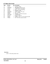
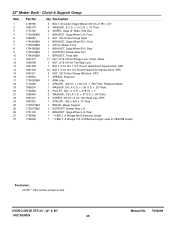
HYDRO DRIVE ZTR 33", 42" & 50" 150Z SERIES 43 Manual No. 7006269 33" Mower Deck Group Item 45 46 47 48 49 50 51 52 53 54 55 56 Part No 7014407 ... Lock 1 HOLDER, Blade 1 BLADE, 33" High Lift 4 SCREW, 1/2-20 x 1-1/4" Hex Head Cap, GR5 1 NUT, 5/8-18 Hex Center Lock Jam Footnotes: NOTE: * Part number printed on belt.
HYDRO DRIVE ZTR 33", 42" & 50" 150Z SERIES 43 Manual No. 7006269 33" Mower Deck Group Item 45 46 47 48 49 50 51 52 53 54 55 56 Part No 7014407 ... Lock 1 HOLDER, Blade 1 BLADE, 33" High Lift 4 SCREW, 1/2-20 x 1-1/4" Hex Head Cap, GR5 1 NUT, 5/8-18 Hex Center Lock Jam Footnotes: NOTE: * Part number printed on belt.
Parts Manual
Page 45
...-18 Hex Flange Lock, Small - x 1.50 O.D. Rear 1 * V-BELT, A Wedge 98.00 Effective Length 1 * V-BELT, A Wedge 103.10 Effective Length (used on 7800388 model) Footnotes: NOTE: * Part number printed on belt. Black 1 NUT, 5/16-18 Hex Two-Way Lock 1 BOLT, 5/...x .87 O.D. Front 1 HITCH, Mower Front 1 BRACKET, Gage Wheel R.H. x .378 I .D. x 1.0 O.D. x 1" 2 WASHER, .3/8 (.41 I .D. HYDRO DRIVE ZTR 33", 42" & 50" 150Z SERIES 45 Manual No. 7006269 Front 4 NUT, 3/8-16 Hex Flange Nyloc 1 BRACKET, Gage Wheel R.H. Clutch & Support Group Item 1 2 3 4 5 6 7 8 9 10 11 12 13 14 15 ...
...-18 Hex Flange Lock, Small - x 1.50 O.D. Rear 1 * V-BELT, A Wedge 98.00 Effective Length 1 * V-BELT, A Wedge 103.10 Effective Length (used on 7800388 model) Footnotes: NOTE: * Part number printed on belt. Black 1 NUT, 5/16-18 Hex Two-Way Lock 1 BOLT, 5/...x .87 O.D. Front 1 HITCH, Mower Front 1 BRACKET, Gage Wheel R.H. x .378 I .D. x 1.0 O.D. x 1" 2 WASHER, .3/8 (.41 I .D. HYDRO DRIVE ZTR 33", 42" & 50" 150Z SERIES 45 Manual No. 7006269 Front 4 NUT, 3/8-16 Hex Flange Nyloc 1 BRACKET, Gage Wheel R.H. Clutch & Support Group Item 1 2 3 4 5 6 7 8 9 10 11 12 13 14 15 ...

Parts Manual
Page 49
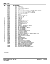
...2812808 1667811 2171247 1960339 1714255 1656936 1733465BM 1924356 1920415 1724387 1931337 1714760 2108765 1960170 1960687 1931353 1714062 Qty Description 1 * V-BELT, (HA Sect., 91.10 Effective Length) Kevlar 1 * V-BELT, (HA sect., 73.12 Effective Length) 1 SCREW, 3/8-16 x 3-1/4" Hex Head Cap, GR5 6 WASHER, ....375 Flat (.41 I .D. x .34 Long, Powdered Metal 1 PULLEY, Idler 5.000 O.D. HYDRO DRIVE ZTR 33", 42" & 50" 150Z SERIES 49 Manual No. 7006269 x .375 ...
...2812808 1667811 2171247 1960339 1714255 1656936 1733465BM 1924356 1920415 1724387 1931337 1714760 2108765 1960170 1960687 1931353 1714062 Qty Description 1 * V-BELT, (HA Sect., 91.10 Effective Length) Kevlar 1 * V-BELT, (HA sect., 73.12 Effective Length) 1 SCREW, 3/8-16 x 3-1/4" Hex Head Cap, GR5 6 WASHER, ....375 Flat (.41 I .D. x .34 Long, Powdered Metal 1 PULLEY, Idler 5.000 O.D. HYDRO DRIVE ZTR 33", 42" & 50" 150Z SERIES 49 Manual No. 7006269 x .375 ...


