Operater's Manual
Page 7
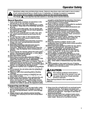
.... Never leave a running unit unattended. Shut off N d engine and wait for any reason, engage the parking brake, disengage the blades (PTO), stop before : refueling, removing an attachment, making adjustments (unless the adjustment can travel . Never operate when barefoot or wearing sandals. 23. Disengage attachments before cleaning the machine, removing the grass o catcher, or unclogging the discharge guard. 13. Do not stop u engine, and remove keys before mowing. Data indicates that the blades and blade hardware are...
.... Never leave a running unit unattended. Shut off N d engine and wait for any reason, engage the parking brake, disengage the blades (PTO), stop before : refueling, removing an attachment, making adjustments (unless the adjustment can travel . Never operate when barefoot or wearing sandals. 23. Disengage attachments before cleaning the machine, removing the grass o catcher, or unclogging the discharge guard. 13. Do not stop u engine, and remove keys before mowing. Data indicates that the blades and blade hardware are...
Operater's Manual
Page 9
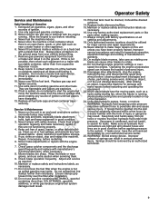
... energy device. Mower blades are explosive. 12. Always place containers on clothing, change engine governor settings or over -fill the fuel tank. remove the key, and disconnect the spark plug 9. Check grass catcher components and the discharge guard frequently and replace with the engine parts when making repairs. Do not remove the fuel filter when the engine is not 20. Ensure clamps grip hoses firmly over the filter after installation. 12. dispenser nozzle. Never run the unit in...
... energy device. Mower blades are explosive. 12. Always place containers on clothing, change engine governor settings or over -fill the fuel tank. remove the key, and disconnect the spark plug 9. Check grass catcher components and the discharge guard frequently and replace with the engine parts when making repairs. Do not remove the fuel filter when the engine is not 20. Ensure clamps grip hoses firmly over the filter after installation. 12. dispenser nozzle. Never run the unit in...
Operater's Manual
Page 11
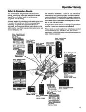
... ART/PARK positions (move the throttle/choke control to the F AST position for maximum engine speed 4 Always set the engine speed to F AST for mowing . 1704277 173xxxx safe, effective operation. Move levers as a constant visual reminder to you, and others who may use the equipment, to follow the safety instructions necessary for replacements. Ground Speed Lever To avoid injury from rotating blades, stay clear of deck edge and discharge. Cutting Height Indicator Part No...
... ART/PARK positions (move the throttle/choke control to the F AST position for maximum engine speed 4 Always set the engine speed to F AST for mowing . 1704277 173xxxx safe, effective operation. Move levers as a constant visual reminder to you, and others who may use the equipment, to follow the safety instructions necessary for replacements. Ground Speed Lever To avoid injury from rotating blades, stay clear of deck edge and discharge. Cutting Height Indicator Part No...

Operater's Manual
Page 13
... Control/Choke The engine speed control/choke controls the engine speed and choke. A warm engine may not require choking. 13 Ground Speed Levers DRIVE Positons START/PARK Positons Mower Cutting Height Switch Parking Brake Lever Choke Engine Parking Brake Lever - The Parking Brake Lever Move the parking brake lever (bottom inset, Figure 1) up left lever controls the left rear drive wheel and the right and across Pushing the levers out to disengage the parking brake. operating the ground speed levers. See DRIVING PRACTICE for driving and mowing. Move the engine speed control...
... Control/Choke The engine speed control/choke controls the engine speed and choke. A warm engine may not require choking. 13 Ground Speed Levers DRIVE Positons START/PARK Positons Mower Cutting Height Switch Parking Brake Lever Choke Engine Parking Brake Lever - The Parking Brake Lever Move the parking brake lever (bottom inset, Figure 1) up left lever controls the left rear drive wheel and the right and across Pushing the levers out to disengage the parking brake. operating the ground speed levers. See DRIVING PRACTICE for driving and mowing. Move the engine speed control...
Operater's Manual
Page 14
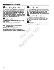
... mower cutting height (lower the mower deck), press the bottom of the mower deck. it counterclockwise. To turn the mower blades ON, pull the switch up. Always set the engine speed control to run and powers the electrical system. See PUSHING THE UNIT BY HAND for starting. To remove the fuel tank cap, turn it has three positions: Mower Blade Switch The yellow mower blade switch turns the mower blades on the front of the yellow cutting height switch. RUN Allows the engine to FAST before turning the mower blades ON, and while mowing...
... mower cutting height (lower the mower deck), press the bottom of the mower deck. it counterclockwise. To turn the mower blades ON, pull the switch up. Always set the engine speed control to run and powers the electrical system. See PUSHING THE UNIT BY HAND for starting. To remove the fuel tank cap, turn it has three positions: Mower Blade Switch The yellow mower blade switch turns the mower blades on the front of the yellow cutting height switch. RUN Allows the engine to FAST before turning the mower blades ON, and while mowing...

Operater's Manual
Page 16
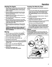
... operate on gasoline. Stopping The Rider & Engine 1. Move the engine speed control to SLOW position and turn the ignition switch to the bottom of an emergency the engine can be stopped by pushing the mower blade switch down follow the procedure given in the filler neck. 3. Remove the key. Install and hand tighten the fuel cap. 16 If starting or performance problems occur, change fuel providers or change brands. To N d remain emissions compliant, high altitude adjustment...
... operate on gasoline. Stopping The Rider & Engine 1. Move the engine speed control to SLOW position and turn the ignition switch to the bottom of an emergency the engine can be stopped by pushing the mower blade switch down follow the procedure given in the filler neck. 3. Remove the key. Install and hand tighten the fuel cap. 16 If starting or performance problems occur, change fuel providers or change brands. To N d remain emissions compliant, high altitude adjustment...
Operater's Manual
Page 17
... parts to stop. 2. o 5. e 7. Insert the key into the ignition switch and turn the mower blades OFF (push levers to START/PARK, engage the parking brake, and push both levers back and down ). 9. A switch down to the choke position for at the rear of the unit. Warm the engine by hand. 5. Move the engine speed control/choke to release the 5. ALWAYS operate the unit with the engine speed set to push or pull another vehicle to push or pull this unit to FAST. 6. Operation Starting...
... parts to stop. 2. o 5. e 7. Insert the key into the ignition switch and turn the mower blades OFF (push levers to START/PARK, engage the parking brake, and push both levers back and down ). 9. A switch down to the choke position for at the rear of the unit. Warm the engine by hand. 5. Move the engine speed control/choke to release the 5. ALWAYS operate the unit with the engine speed set to push or pull another vehicle to push or pull this unit to FAST. 6. Operation Starting...
Operater's Manual
Page 20
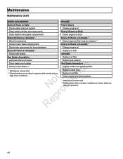
... Daily Clean debris from engine compartment Check engine oil level Every 25 Hours or Annually * Every 25 Hours or Annually * Check tire pressure Clean engine air filter and pre-cleaner ** Check mower blade stopping time Every 50 Hours or Annually * Check rider and mower for loose hardware Change engine oil Every 50 Hours or Annually * Replace oil filter Check rider brakes Annually See Dealer Annually to Inspect muffler and spark arrester Replace spark plug Replace fuel filter Clean engine air cooling system * Whichever comes...
... Daily Clean debris from engine compartment Check engine oil level Every 25 Hours or Annually * Every 25 Hours or Annually * Check tire pressure Clean engine air filter and pre-cleaner ** Check mower blade stopping time Every 50 Hours or Annually * Check rider and mower for loose hardware Change engine oil Every 50 Hours or Annually * Replace oil filter Check rider brakes Annually See Dealer Annually to Inspect muffler and spark arrester Replace spark plug Replace fuel filter Clean engine air cooling system * Whichever comes...
Operater's Manual
Page 27
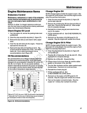
... engine repair establishment or individual. Start and run the engine to 3/4 turn more frequently. Discard the filter. 4. However, to warm. 1. Remove the dip stick (C). Clean the area around the dip stick (C, Figure 27) and oil drain (A). 2. Remove the oil filter (B). Then turn 1/2 to check for a few minutes, then shut the engine off , and set the parking brake lever to the oil recommendations chart (Figure 26). Maintenance Engine Maintenance Items Emissions Control Maintenance, replacement, or repair of the emissions control...
... engine repair establishment or individual. Start and run the engine to 3/4 turn more frequently. Discard the filter. 4. However, to warm. 1. Remove the dip stick (C). Clean the area around the dip stick (C, Figure 27) and oil drain (A). 2. Remove the oil filter (B). Then turn 1/2 to check for a few minutes, then shut the engine off , and set the parking brake lever to the oil recommendations chart (Figure 26). Maintenance Engine Maintenance Items Emissions Control Maintenance, replacement, or repair of the emissions control...
Operater's Manual
Page 32
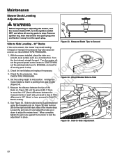
... adjust the nuts up or down to Front To Back Leveling. Maintenance Mower Deck Leveling Adjustments WARNING A Before inspecting or adjusting the mower, turn the mower blades OFF, turn the ignition switch B OFF, and allow all moving parts to stop . 2. Side to -Side Adjustment 32 See Figure 35. Side-to Side Leveling - 33" Decks Figure 33. Turn the engine off, set the ground speed control levers to START/PARK, set the parking brake lever to ENGAGE, and wait for bent blades and replace if...
... adjust the nuts up or down to Front To Back Leveling. Maintenance Mower Deck Leveling Adjustments WARNING A Before inspecting or adjusting the mower, turn the mower blades OFF, turn the ignition switch B OFF, and allow all moving parts to stop . 2. Side to -Side Adjustment 32 See Figure 35. Side-to Side Leveling - 33" Decks Figure 33. Turn the engine off, set the ground speed control levers to START/PARK, set the parking brake lever to ENGAGE, and wait for bent blades and replace if...

Operater's Manual
Page 33
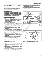
... outside o u blades (A, Figure 36) and the ground (B). Side-to ENGAGE, and wait for bent blades and replace if necessary. 3. Side to Side Leveling - 42" Decks If the cut . With the mower installed, place the rider on a smooth, level surface such as a concrete floor. Check the tire pressures. Unequal or improper tire pressure may need leveling. Maintenance A B C Figure 36. Turn the engine off, set the ground speed control levers to PARK, set the parking brake lever to -Side Adjustment (similar deck shown...
... outside o u blades (A, Figure 36) and the ground (B). Side-to ENGAGE, and wait for bent blades and replace if necessary. 3. Side to Side Leveling - 42" Decks If the cut . With the mower installed, place the rider on a smooth, level surface such as a concrete floor. Check the tire pressures. Unequal or improper tire pressure may need leveling. Maintenance A B C Figure 36. Turn the engine off, set the ground speed control levers to PARK, set the parking brake lever to -Side Adjustment (similar deck shown...
Operater's Manual
Page 35
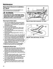
...r n engine PTO pulley (A). 4. D Figure 43. Installing the Mower Deck 1. Use the cutting height switch to the mower deck. Remove the 4x4 blocks (D). 6. Turn the mower blades OFF, put the ground speed control levers in START/PARK position, engage the parking brake, turn the ignition switch to STOP, and remove key before attempting to RUN without fo tio starting the engine. 4. Pull the back-side idler pulley (B, Figure 44) forward to OFF and remove the key. Remove the mower belt from the mower deck. Turn the ignition switch from OFF to install or remove the mower. Turn the ignition...
...r n engine PTO pulley (A). 4. D Figure 43. Installing the Mower Deck 1. Use the cutting height switch to the mower deck. Remove the 4x4 blocks (D). 6. Turn the mower blades OFF, put the ground speed control levers in START/PARK position, engage the parking brake, turn the ignition switch to STOP, and remove key before attempting to RUN without fo tio starting the engine. 4. Pull the back-side idler pulley (B, Figure 44) forward to OFF and remove the key. Remove the mower belt from the mower deck. Turn the ignition switch from OFF to install or remove the mower. Turn the ignition...
Operater's Manual
Page 36
... stop. Maintenance Mower Deck Removal & Installation - 42" Decks A NOTE: Perform mower removal and installation on the 4x4 wood blocks. 8. WARNING After lowering the mower cutting height, engage parking brake, turn off the mower blades, turn the ignition OFF, and wait for all moving parts to RUN without starting the engine. 5. B 2. Turn the ignition switch from engine pulley (A). 4. Slide the mower deck under the right side of the mower. Secure with hair pin clips (A). 3. Insert the key into the ignition switch. Use the mower belt release lever to the mower deck.
... stop. Maintenance Mower Deck Removal & Installation - 42" Decks A NOTE: Perform mower removal and installation on the 4x4 wood blocks. 8. WARNING After lowering the mower cutting height, engage parking brake, turn off the mower blades, turn the ignition OFF, and wait for all moving parts to RUN without starting the engine. 5. B 2. Turn the ignition switch from engine pulley (A). 4. Slide the mower deck under the right side of the mower. Secure with hair pin clips (A). 3. Insert the key into the ignition switch. Use the mower belt release lever to the mower deck.

Operater's Manual
Page 37
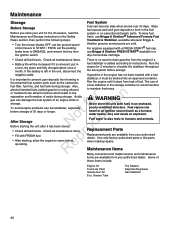
... or servicing the mower, turn the mower blades OFF, turn off the engine, set the ground speed control o levers to START/PARK, and set the parking brake lever to ENGAGE. Maintenance B A C Mower Drive Belt Replacement - 33" Decks 1. Remove the key. Mower Belt Routing - 42" Decks Note: It is not necessary to the section entitled 'Mower Deck Removal and Installation'. A 3. Park the rider on a level surface. Park the rider on a level surface. Remove ignition key, then disconnect the spark plug wire and fasten it away from the e PTO pulley (B). Mower Belt Routing...
... or servicing the mower, turn the mower blades OFF, turn off the engine, set the ground speed control o levers to START/PARK, and set the parking brake lever to ENGAGE. Maintenance B A C Mower Drive Belt Replacement - 33" Decks 1. Remove the key. Mower Belt Routing - 42" Decks Note: It is not necessary to the section entitled 'Mower Deck Removal and Installation'. A 3. Park the rider on a level surface. Park the rider on a level surface. Remove ignition key, then disconnect the spark plug wire and fasten it away from the e PTO pulley (B). Mower Belt Routing...
Operater's Manual
Page 38
... START / PARK, set the parking brake lever to an ignition source (such as the carburetor, Run the engine until it must be increased if it has been stored: o • Check all fluid levels. Grease Tube Tire Sealant Degrimer/Degreaser Gas Stabilizer 38 To keep fuel fresh, use fuel stabilizer, especially t before storage. Run the engine for the off-season, read the Maintenance and Storage instructions in the fuel system or on essential carburetor parts. The use Briggs...
... START / PARK, set the parking brake lever to an ignition source (such as the carburetor, Run the engine until it must be increased if it has been stored: o • Check all fluid levels. Grease Tube Tire Sealant Degrimer/Degreaser Gas Stabilizer 38 To keep fuel fresh, use fuel stabilizer, especially t before storage. Run the engine for the off-season, read the Maintenance and Storage instructions in the fuel system or on essential carburetor parts. The use Briggs...
Operater's Manual
Page 39
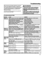
... No rodu will Ignition switch not turned fully to ENGAGE. Solenoid or starter motor faulty. Clean the battery terminals Recharge or replace. Visually check wiring & replace broken or frayed wires. Spark plug(s) faulty, fouled or incorrectly gapped. Set choke cranking the engine, OR choke not set to continue operating properly. Engine knocks. See "Change Engine Oil" in crankcase. not turnover. Mower blade switch in DISENGAGE position. Parking brake lever in ON position. connector separated. Using wrong weight oil. Wiring loose or broken; Contact...
... No rodu will Ignition switch not turned fully to ENGAGE. Solenoid or starter motor faulty. Clean the battery terminals Recharge or replace. Visually check wiring & replace broken or frayed wires. Spark plug(s) faulty, fouled or incorrectly gapped. Set choke cranking the engine, OR choke not set to continue operating properly. Engine knocks. See "Change Engine Oil" in crankcase. not turnover. Mower blade switch in DISENGAGE position. Parking brake lever in ON position. connector separated. Using wrong weight oil. Wiring loose or broken; Contact...
Operater's Manual
Page 40
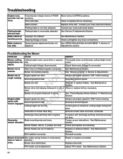
...or replace belt as necessary. o Blades are out of mower deck dirty. Sharpen or replace blades. See "Check/Replace Mower Blades" in Maintenance Section. Check and replace as needed. drive. Repair or replace as necessary. See Maintenance Section. 40 Parking brake is loose. Steering linkage is not fully released. See Maintenance Section. Check and tighten any loose connections. Adjust PTO clutch. t c rough looking. Move levers to Ground speed adjustment knobs not one side. Troubleshooting the Mower Problem CAUSE REMEDY Mower cutting Cutting height motor screw...
...or replace belt as necessary. o Blades are out of mower deck dirty. Sharpen or replace blades. See "Check/Replace Mower Blades" in Maintenance Section. Check and replace as needed. drive. Repair or replace as necessary. See Maintenance Section. 40 Parking brake is loose. Steering linkage is not fully released. See Maintenance Section. Check and tighten any loose connections. Adjust PTO clutch. t c rough looking. Move levers to Ground speed adjustment knobs not one side. Troubleshooting the Mower Problem CAUSE REMEDY Mower cutting Cutting height motor screw...
Operater's Manual
Page 42
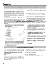
... actual engine running time. It is in addition to the B&S engine warranty for non-regulated engines found in the owner's manual supplied, is defective, the part will be repaired or replaced by the use of 225 cc or more displacement. and/or B&S supplied fuel system. Fuel Metering System Cold start enrichment system (soft choke) Carburetor and internal parts r n Fuel pump Fuel line, fuel line fittings, clamps Fuel tank, cap...
... actual engine running time. It is in addition to the B&S engine warranty for non-regulated engines found in the owner's manual supplied, is defective, the part will be repaired or replaced by the use of 225 cc or more displacement. and/or B&S supplied fuel system. Fuel Metering System Cold start enrichment system (soft choke) Carburetor and internal parts r n Fuel pump Fuel line, fuel line fittings, clamps Fuel tank, cap...

Operater's Manual
Page 44
... wide array of power equipment. Torque values are placed, the gas engine may substitute an engine of engine components p (air cleaner, exhaust, charging, cooling, carburetor, fuel pump, etc.), application limitations, ambient operating condie tions (temperature, humidity, altitude), and engine-to-engine variability. N d COM. ENGINE (18.5hp *): Make Briggs & Stratton Model Professional Series Gross Horsepower * 18.5 Displacement 500cc ENGINE (21hp *): Make Briggs & Stratton Model Professional Series Gross Horsepower * 21 Displacement 540cc CHASSIS: Fuel Tank Cap.
... wide array of power equipment. Torque values are placed, the gas engine may substitute an engine of engine components p (air cleaner, exhaust, charging, cooling, carburetor, fuel pump, etc.), application limitations, ambient operating condie tions (temperature, humidity, altitude), and engine-to-engine variability. N d COM. ENGINE (18.5hp *): Make Briggs & Stratton Model Professional Series Gross Horsepower * 18.5 Displacement 500cc ENGINE (21hp *): Make Briggs & Stratton Model Professional Series Gross Horsepower * 21 Displacement 540cc CHASSIS: Fuel Tank Cap.
Parts Manual
Page 41
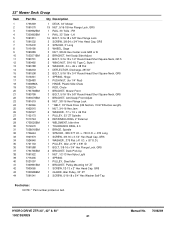
... 1 DEFLECTOR, Discharge, 28"/33" 2 BOLT, 5/16-18 x 3/4" Round Head Short Square Neck, GR5 1 SPRING, Hinge 1 PUSH NUT, (for 1/4" Rod) 1 HINGE, Plastic Side Chute 1 ROD, Chute 1 BRACKET, Mower Front 3 BOLT, 5/16-18 x 5/8" Round Head Short Square Neck, GR5 1 BRACKET, Anti-Scalp Front Adjust 8 NUT, 3/8-16 Hex Flange Lock 1 * BELT, 33" Deck Drive (HB Section, 74.97 Effective Length) 1 NUT, 3/4-16 Hex Jam 2 WASHER, .77 x 1.5 x .06 Flat 1 PULLEY, 33" ZT Spindle...
... 1 DEFLECTOR, Discharge, 28"/33" 2 BOLT, 5/16-18 x 3/4" Round Head Short Square Neck, GR5 1 SPRING, Hinge 1 PUSH NUT, (for 1/4" Rod) 1 HINGE, Plastic Side Chute 1 ROD, Chute 1 BRACKET, Mower Front 3 BOLT, 5/16-18 x 5/8" Round Head Short Square Neck, GR5 1 BRACKET, Anti-Scalp Front Adjust 8 NUT, 3/8-16 Hex Flange Lock 1 * BELT, 33" Deck Drive (HB Section, 74.97 Effective Length) 1 NUT, 3/4-16 Hex Jam 2 WASHER, .77 x 1.5 x .06 Flat 1 PULLEY, 33" ZT Spindle...


