
Operater's Manual
Page 5
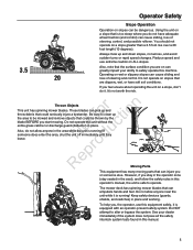
... sliding, loss of steering and control. However, if you or someone does enter the area, shut the unit off immediately until they N d leave. The mower deck has spinning mower blades that are on ALL slopes. You should not operate on a slope, don't do not have soft soil conditions. Reduce speed and...
... sliding, loss of steering and control. However, if you or someone does enter the area, shut the unit off immediately until they N d leave. The mower deck has spinning mower blades that are on ALL slopes. You should not operate on a slope, don't do not have soft soil conditions. Reduce speed and...
Operater's Manual
Page 7
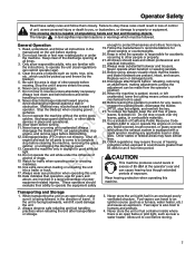
.... Read, understand, and follow them closely. fo tio 9. Never leave a running unit unattended. All drivers should Wear hearing protection when operating this unit. This mowing deck is also toxic to operate the unit (local regulations can be picked up and thrown by the blade(s). 5. c 11. It is facing backwards, wind lift...
.... Read, understand, and follow them closely. fo tio 9. Never leave a running unit unattended. All drivers should Wear hearing protection when operating this unit. This mowing deck is also toxic to operate the unit (local regulations can be picked up and thrown by the blade(s). 5. c 11. It is facing backwards, wind lift...
Operater's Manual
Page 11
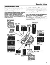
... ignition switch to DISENGAGE position. 3. Decal - Contact your rider and mower. Parking Brake Part No. 7102578 1 Low Cut 1733458 (42" Decks) Part No. 1704276 Decal - unit to remind you of these instructions are easily applied and will return to RUN position) -move both ground...been designed and manufactured to All DANGER, WARNING, CAUTION and instructional provide you with hot surfaces. Amputation and Thrown Objects Hazard (33" Decks) Part No. 7101665 11 Move engine speed control to turn the mower blades ON. Push the mower blade switch DOWN to SLOW. ...
... ignition switch to DISENGAGE position. 3. Decal - Contact your rider and mower. Parking Brake Part No. 7102578 1 Low Cut 1733458 (42" Decks) Part No. 1704276 Decal - unit to remind you of these instructions are easily applied and will return to RUN position) -move both ground...been designed and manufactured to All DANGER, WARNING, CAUTION and instructional provide you with hot surfaces. Amputation and Thrown Objects Hazard (33" Decks) Part No. 7101665 11 Move engine speed control to turn the mower blades ON. Push the mower blade switch DOWN to SLOW. ...
Operater's Manual
Page 14
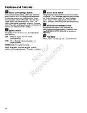
... battery. 14 Features and Controls Mower Cutting Height Switch To increase the mower cutting height (raise the mower deck), press the top of the mower deck. To decrease mower cutting height (lower the mower deck), press the bottom of the rider, just behind the driver's left leg. Mower cutting height range is located...
... battery. 14 Features and Controls Mower Cutting Height Switch To increase the mower cutting height (raise the mower deck), press the top of the mower deck. To decrease mower cutting height (lower the mower deck), press the bottom of the rider, just behind the driver's left leg. Mower cutting height range is located...
Operater's Manual
Page 20
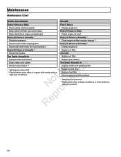
... Chart XXXXXXXXX RIDER AND MOWER ENGINE Every 8 Hours or Daily First 5 Hours Check safety interlock system Change engine oil Clean debris off rider and mower deck Every 8 Hours or Daily Clean debris from engine compartment Check engine oil level Every 25 Hours or Annually * Every 25 Hours or Annually * Check tire...
... Chart XXXXXXXXX RIDER AND MOWER ENGINE Every 8 Hours or Daily First 5 Hours Check safety interlock system Change engine oil Clean debris off rider and mower deck Every 8 Hours or Daily Clean debris from engine compartment Check engine oil level Every 25 Hours or Annually * Every 25 Hours or Annually * Check tire...
Operater's Manual
Page 21
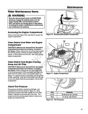
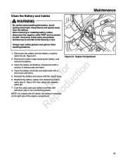
...Figure 11. Engine Compartment remove any debris that these pressures may differ slightly from the intake screen on the side-wall of the seat deck to stop before accessing the engine compartment or performing any grass clippings, dirt, leaves, or other hot surfaces, it creates a fire ... filter assembly. Check Tire Pressure Tire pressure should be checked periodically, and maintained at the beginning of the mowing session, lift the seat deck and clean any e debris from the "Max Inflation" stamped on top of fo tio the mowing session, remove any maintenance procedures. Accessing...
...Figure 11. Engine Compartment remove any debris that these pressures may differ slightly from the intake screen on the side-wall of the seat deck to stop before accessing the engine compartment or performing any grass clippings, dirt, leaves, or other hot surfaces, it creates a fire ... filter assembly. Check Tire Pressure Tire pressure should be checked periodically, and maintained at the beginning of the mowing session, lift the seat deck and clean any e debris from the "Max Inflation" stamped on top of fo tio the mowing session, remove any maintenance procedures. Accessing...

Operater's Manual
Page 22
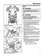
...; front wheel bushings • mower pivots • mower arbors Use grease fittings when present. Mower Lubrication - 42" Deck • brake linkage • mower deck height adjustment linkage • ground speed control linkage Generally, all greases are compatible. Arbor Lubrication RNeprod(3-Blade Model Shown, All... grease off belts and pulleys. ot fo uctio Figure 15. Oil: • hydro linkage Figure 14. Mower Lubrication - 33" Deck 22 Not all moving metal parts should be oiled where contact is made with other parts. Maintenance Lubrication Lubricate the unit at the...
...; front wheel bushings • mower pivots • mower arbors Use grease fittings when present. Mower Lubrication - 42" Deck • brake linkage • mower deck height adjustment linkage • ground speed control linkage Generally, all greases are compatible. Arbor Lubrication RNeprod(3-Blade Model Shown, All... grease off belts and pulleys. ot fo uctio Figure 15. Oil: • hydro linkage Figure 14. Mower Lubrication - 33" Deck 22 Not all moving metal parts should be oiled where contact is made with other parts. Maintenance Lubrication Lubricate the unit at the...
Operater's Manual
Page 23
... fine edge. A r balanced blade will remain level. Reinstall the blade (A, Figures 22 & 23) with bare hands. Lubricating Rider Maintenance Clean Deck & Check / Replace Mower Blades WARNING For your personal safety, blade mounting hardware must be installed as shown in Figures 22 and 23. Remove the... hardware and blade. Lubricating Rider Figure 17. Figure 16. Remove mower deck (see "Mower Deck Removal"). 2. Inspect the blade(s) for nicks or dull edges. Use a o ufile to sharpen blade to prevent blade r n rotation...
... fine edge. A r balanced blade will remain level. Reinstall the blade (A, Figures 22 & 23) with bare hands. Lubricating Rider Maintenance Clean Deck & Check / Replace Mower Blades WARNING For your personal safety, blade mounting hardware must be installed as shown in Figures 22 and 23. Remove the... hardware and blade. Lubricating Rider Figure 17. Figure 16. Remove mower deck (see "Mower Deck Removal"). 2. Inspect the blade(s) for nicks or dull edges. Use a o ufile to sharpen blade to prevent blade r n rotation...
Operater's Manual
Page 24
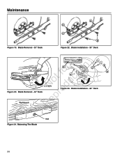
Blade Installation - 33" Deck r n F E C fo tio A ot uc LOOSEN N od Figure 20. Blade Installation - 42" Deck epr Workbench R Blade Removal.epsf D Nail Figure 21. Maintenance Figure 19. Balancing The Blade Blade Balancing.eps 24 Blade Removal - 42" Deck Figure 23. Blade Removal - 33" Deck A D C B Figure 22.
Blade Installation - 33" Deck r n F E C fo tio A ot uc LOOSEN N od Figure 20. Blade Installation - 42" Deck epr Workbench R Blade Removal.epsf D Nail Figure 21. Maintenance Figure 19. Balancing The Blade Blade Balancing.eps 24 Blade Removal - 42" Deck Figure 23. Blade Removal - 33" Deck A D C B Figure 22.
Operater's Manual
Page 25
... frame by a tool. Figure 24. When removing or installing battery cables, disconnect the negative cable FIRST and reconnect it LAST. o Note: On models with 33" decks, the battery is mounted Repr on the right side of baking soda and water. Maintenance Clean the Battery and Cables WARNING Be careful when handling...
... frame by a tool. Figure 24. When removing or installing battery cables, disconnect the negative cable FIRST and reconnect it LAST. o Note: On models with 33" decks, the battery is mounted Repr on the right side of baking soda and water. Maintenance Clean the Battery and Cables WARNING Be careful when handling...
Operater's Manual
Page 30
... C A B MORWAIESRE HCeuitgthintg MLOO1W7W342E7E6RR 4 High Cut 3 2 1 1733458 Low Cut Cutting Height Adjustment To increase the mower cutting height (raise the mower deck), press the top of the mower cutting height switch (A, Figure 31) To decrease mower cutting height (lower the mower...Balancing Adjustment N d If the rider veers to lock the carriage bolt in the maximum forward o position, the top speed of the mower deck.. The cutting height gauge (B) is 3-3/4" to their DRIVE positions. The cutting height gauge indicates the position of the right lever can be ...
... C A B MORWAIESRE HCeuitgthintg MLOO1W7W342E7E6RR 4 High Cut 3 2 1 1733458 Low Cut Cutting Height Adjustment To increase the mower cutting height (raise the mower deck), press the top of the mower cutting height switch (A, Figure 31) To decrease mower cutting height (lower the mower...Balancing Adjustment N d If the rider veers to lock the carriage bolt in the maximum forward o position, the top speed of the mower deck.. The cutting height gauge (B) is 3-3/4" to their DRIVE positions. The cutting height gauge indicates the position of the right lever can be ...
Operater's Manual
Page 32
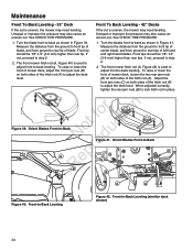
... to step 6. See Figure 35. Side-to mid position. Set the cutting height to -Side Adjustment 32 N d 5. e 6. Maintenance Mower Deck Leveling Adjustments WARNING A Before inspecting or adjusting the mower, turn the mower blades OFF, turn the ignition switch B OFF, and allow all moving parts.... Remove ignition key, then disconnect the spark plug wire and fasten it is more than 1/8" (3mm) difference between the tips of the mower deck. Check the tire pressures. Side-to lock the adjustment in place. Loosen the jam nuts (C) and adjust the nuts up or down to -...
... to step 6. See Figure 35. Side-to mid position. Set the cutting height to -Side Adjustment 32 N d 5. e 6. Maintenance Mower Deck Leveling Adjustments WARNING A Before inspecting or adjusting the mower, turn the mower blades OFF, turn the ignition switch B OFF, and allow all moving parts.... Remove ignition key, then disconnect the spark plug wire and fasten it is more than 1/8" (3mm) difference between the tips of the mower deck. Check the tire pressures. Side-to lock the adjustment in place. Loosen the jam nuts (C) and adjust the nuts up or down to -...

Operater's Manual
Page 33
...5. Measure the distance between the N d measurements on each side, proceed to step 6. If there is more than 1/8" (3mm) difference between the tips of the mower deck. Remove ignition key, then disconnect the spark plug wire and fasten it away from side-toside (Figure 37). Check for all moving parts to stop... . Figure 38. Set the cutting height to -Side Adjustment (similar deck shown) 33 Side to Side Leveling - 42" Decks If the cut is uneven, the mower may also cause an uneven cut. Side-to mid position. r 6.
...5. Measure the distance between the N d measurements on each side, proceed to step 6. If there is more than 1/8" (3mm) difference between the tips of the mower deck. Remove ignition key, then disconnect the spark plug wire and fasten it away from side-toside (Figure 37). Check for all moving parts to stop... . Figure 38. Set the cutting height to -Side Adjustment (similar deck shown) 33 Side to Side Leveling - 42" Decks If the cut is uneven, the mower may also cause an uneven cut. Side-to mid position. r 6.
Operater's Manual
Page 34
... -back as shown in Figure 39. Orient Blades Front-to -Back C C B B A A Figure 40. To raise or lower the front of mower deck, adjust the front jam nuts (B) on both sides of the hitch rod (A). Unequal or improper tire pressure may also cause an uneven cut . The front... is used to adjust front-to -back leveling. Front tips should be 1/8"-1/4" (3-6 mm) higher than rear tip. Turn the blade front-to adjust the deck level. Front tip should be 1/8"-1/4" (3-6 mm) higher than rear tips. Front-to step 2. 2. If not, proceed to -Back Leveling Figure 42. ...
... -back as shown in Figure 39. Orient Blades Front-to -Back C C B B A A Figure 40. To raise or lower the front of mower deck, adjust the front jam nuts (B) on both sides of the hitch rod (A). Unequal or improper tire pressure may also cause an uneven cut . The front... is used to adjust front-to -back leveling. Front tips should be 1/8"-1/4" (3-6 mm) higher than rear tip. Turn the blade front-to adjust the deck level. Front tip should be 1/8"-1/4" (3-6 mm) higher than rear tips. Front-to step 2. 2. If not, proceed to -Back Leveling Figure 42. ...
Operater's Manual
Page 35
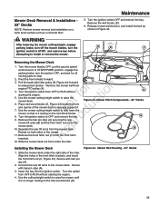
... until it is it . Separate the rear lift arms from r n engine PTO pulley (A). 4. t c 6. p 10. o 9. Mower Hitch Components - 33" Decks A B 12. Release mower belt tension, and install the belt as a concrete floor. Pull the back-side idler pulley (B, Figure 44) forward to install or remove... the mower. Use the cutting height switch to RUN without fo tio starting the engine. 4. Installing the Mower Deck 1. Mower Deck Removal & Installation 33" Decks NOTE: Perform mower removal and installation on a hard, level surface such as shown in Figure 44. Turn the switch from...
... until it is it . Separate the rear lift arms from r n engine PTO pulley (A). 4. t c 6. p 10. o 9. Mower Hitch Components - 33" Decks A B 12. Release mower belt tension, and install the belt as a concrete floor. Pull the back-side idler pulley (B, Figure 44) forward to install or remove... the mower. Use the cutting height switch to RUN without fo tio starting the engine. 4. Installing the Mower Deck 1. Mower Deck Removal & Installation 33" Decks NOTE: Perform mower removal and installation on a hard, level surface such as shown in Figure 44. Turn the switch from...
Operater's Manual
Page 36
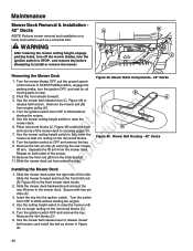
... Separate the lift arm from the hitch bracket. p 10. Remove the hitch rod (B) from the mower deck. C Figure 46. Maintenance Mower Deck Removal & Installation - 42" Decks A NOTE: Perform mower removal and installation on the 4x4 wood blocks. 8. Turn the ignition switch to install... or remove the mower. Mower Belt Routing - 42" Decks R Installing the Mower Deck A 1. Turn the ignition switch OFF and remove the key. Insert the key into the ignition switch. Pivot the front wheels...
... Separate the lift arm from the hitch bracket. p 10. Remove the hitch rod (B) from the mower deck. C Figure 46. Maintenance Mower Deck Removal & Installation - 42" Decks A NOTE: Perform mower removal and installation on the 4x4 wood blocks. 8. Turn the ignition switch to install... or remove the mower. Mower Belt Routing - 42" Decks R Installing the Mower Deck A 1. Turn the ignition switch OFF and remove the key. Insert the key into the ignition switch. Pivot the front wheels...

Operater's Manual
Page 37
... turn off the engine, set the ground speed control levers to START/PARK, and set the parking brake r lever to the section entitled 'Mower Deck Removal and Installation'. Remove the key. Remove the belt from the spark plug. Figure 47. Refer to ENGAGE. Park the rider on a level surface... the parking brake lever to release belt tension and remove the mower drive belt (B) from the B PTO pulley (A). Mower Belt Routing - 33" Decks 2. Pull the idler pulley (C, Figure 47) to ENGAGE. Note: The left rear threaded rod must be removed from the mower in order to ...
... turn off the engine, set the ground speed control levers to START/PARK, and set the parking brake r lever to the section entitled 'Mower Deck Removal and Installation'. Remove the key. Remove the belt from the spark plug. Figure 47. Refer to ENGAGE. Park the rider on a level surface... the parking brake lever to release belt tension and remove the mower drive belt (B) from the B PTO pulley (A). Mower Belt Routing - 33" Decks 2. Pull the idler pulley (C, Figure 47) to ENGAGE. Note: The left rear threaded rod must be removed from the mower in order to ...
Operater's Manual
Page 40
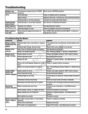
... poorly. Mower not leveled properly. o Blades are bent. Cut tall grass at maximum cutting height during first pass. Remove mower deck and clean underside. See Maintenance Section. Troubleshooting Engine runs, Transmission release levers in Service & Adjustments. Move levers to attached. Adjust...adjusted. See SPEED BALANCING ADJUSTMENT in Maintenance Section. Excessive Blade mounting nuts are out of balance. PTO clutch out of mower deck dirty. Ground speed too fast. r n Mower cut area. Mower drive belt Idler pulley spring broken or not properly slips ...
... poorly. Mower not leveled properly. o Blades are bent. Cut tall grass at maximum cutting height during first pass. Remove mower deck and clean underside. See Maintenance Section. Troubleshooting Engine runs, Transmission release levers in Service & Adjustments. Move levers to attached. Adjust...adjusted. See SPEED BALANCING ADJUSTMENT in Maintenance Section. Excessive Blade mounting nuts are out of balance. PTO clutch out of mower deck dirty. Ground speed too fast. r n Mower cut area. Mower drive belt Idler pulley spring broken or not properly slips ...

Parts Manual
Page 3
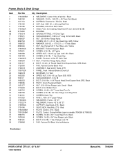
Clutch & Support Group 42" Mower Deck - PAGE 4 6 10 14 18 22 26 30 32 34 36 38 40 44 46 48 50 52 54 GROUP Wheel & Tire Group Frame, Body & Seat ... (18.5 H.P.) Engine Group (20 H.P.) Engine Group (21 H.P.) Engine Group (26 H.P.) Decal Group Mower Lift Group (33" Deck) Mower Lift Group (42" Deck) Mower Lift Group (50" Deck) 33" Mower Deck Group 42" Mower Deck - Clutch & Support Group 50" Mower Deck - Housing & Arbor Group Electrical Group Wiring Schematic Table Of Contents HYDRO DRIVE ZTR 33", 42" & 50...
Clutch & Support Group 42" Mower Deck - PAGE 4 6 10 14 18 22 26 30 32 34 36 38 40 44 46 48 50 52 54 GROUP Wheel & Tire Group Frame, Body & Seat ... (18.5 H.P.) Engine Group (20 H.P.) Engine Group (21 H.P.) Engine Group (26 H.P.) Decal Group Mower Lift Group (33" Deck) Mower Lift Group (42" Deck) Mower Lift Group (50" Deck) 33" Mower Deck Group 42" Mower Deck - Clutch & Support Group 50" Mower Deck - Housing & Arbor Group Electrical Group Wiring Schematic Table Of Contents HYDRO DRIVE ZTR 33", 42" & 50...
Parts Manual
Page 7
...x 3/4" Hex Flange Lock, Black 4 BOLT, 5/16-18 x 1" Hex Flange Lock YZ 1 PAD, Footrest RH Black Vinyl w/Adhesive Footnotes: HYDRO DRIVE ZTR 33", 42" & 50" 150Z SERIES 7 Manual No. 7006269 x 1.75 O.D. x .11 Thick, Black 1 NUT, Hex Flange 5/8-11 Two Way Lock, Yellow 1 BRACKET, Footrest Support, Black 2 SCREW, 5/16-18... BOLT, 1/4-20 x 2" Round Head Short Square Neck, GR5, Black 1 PAD, Footrest Center Black Vinyl 1 ASSEMBLY, Seat w/Arm Rests, ZTR 1 PANEL, Front - Black 1 SEAT DECK, Red Poly, ZTS - Frame, Body & Seat Group Item 1 2 3 4 5 6 6A 6B 7 8 9 10 11 12 13 14 15 16 17 18 19 20 21 ...
...x 3/4" Hex Flange Lock, Black 4 BOLT, 5/16-18 x 1" Hex Flange Lock YZ 1 PAD, Footrest RH Black Vinyl w/Adhesive Footnotes: HYDRO DRIVE ZTR 33", 42" & 50" 150Z SERIES 7 Manual No. 7006269 x 1.75 O.D. x .11 Thick, Black 1 NUT, Hex Flange 5/8-11 Two Way Lock, Yellow 1 BRACKET, Footrest Support, Black 2 SCREW, 5/16-18... BOLT, 1/4-20 x 2" Round Head Short Square Neck, GR5, Black 1 PAD, Footrest Center Black Vinyl 1 ASSEMBLY, Seat w/Arm Rests, ZTR 1 PANEL, Front - Black 1 SEAT DECK, Red Poly, ZTS - Frame, Body & Seat Group Item 1 2 3 4 5 6 6A 6B 7 8 9 10 11 12 13 14 15 16 17 18 19 20 21 ...
