
Operater's Manual
Page 11
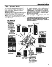
...Move ground speed levers to DISENGAGE position. 3. Tracking Part No. 7103082 Adjustment Decal - Parking Brake Part No. 7102578 1 Low Cut 1733458 (42" Decks) Part No. 1704276 Decal - knowledge to operate this equipment safely and If any of this manual and the safety instructions it contains ...mower blades OFF. 7102575 1 Sit in outdoor power read and obeyed. To Turn the Mower Blades Off: 1. Amputation and Thrown Objects Hazard (42" Decks) Part No. 1704277 DANGER Amputation and Thrown Objects Hazard To avoid injury from an industry leader in the seat. 3 5 2 Move...
...Move ground speed levers to DISENGAGE position. 3. Tracking Part No. 7103082 Adjustment Decal - Parking Brake Part No. 7102578 1 Low Cut 1733458 (42" Decks) Part No. 1704276 Decal - knowledge to operate this equipment safely and If any of this manual and the safety instructions it contains ...mower blades OFF. 7102575 1 Sit in outdoor power read and obeyed. To Turn the Mower Blades Off: 1. Amputation and Thrown Objects Hazard (42" Decks) Part No. 1704277 DANGER Amputation and Thrown Objects Hazard To avoid injury from an industry leader in the seat. 3 5 2 Move...

Operater's Manual
Page 22
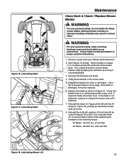
... as the following lubrication points. Use automotive-type lithium grease. Keep oil and grease off belts and pulleys. Mower Lubrication - 33" Deck 22 Mower Lubrication - 42" Deck • brake linkage • mower deck height adjustment linkage • ground speed control linkage Generally, all greases are compatible. Remember to wipe fittings and...
... as the following lubrication points. Use automotive-type lithium grease. Keep oil and grease off belts and pulleys. Mower Lubrication - 33" Deck 22 Mower Lubrication - 42" Deck • brake linkage • mower deck height adjustment linkage • ground speed control linkage Generally, all greases are compatible. Remember to wipe fittings and...
Operater's Manual
Page 23
... side until it must each be replaced. A r balanced blade will remain level. Reinstall the blade (A, Figures 22 & 23) with bare hands. lbs. (41-54 Nm) 42" Blade - 80-90 ft. WARNING For your personal safety, do not handle the sharp mower blades with the lift wings (E, Figure 23) pointing up toward...
... side until it must each be replaced. A r balanced blade will remain level. Reinstall the blade (A, Figures 22 & 23) with bare hands. lbs. (41-54 Nm) 42" Blade - 80-90 ft. WARNING For your personal safety, do not handle the sharp mower blades with the lift wings (E, Figure 23) pointing up toward...
Operater's Manual
Page 24
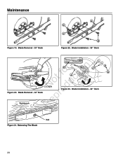
Balancing The Blade Blade Balancing.eps 24 Maintenance Figure 19. Blade Removal - 42" Deck Figure 23. Blade Installation - 33" Deck r n F E C fo tio A ot uc LOOSEN N od Figure 20. Blade Removal - 33" Deck A D C B Figure 22. Blade Installation - 42" Deck epr Workbench R Blade Removal.epsf D Nail Figure 21.
Balancing The Blade Blade Balancing.eps 24 Maintenance Figure 19. Blade Removal - 42" Deck Figure 23. Blade Installation - 33" Deck r n F E C fo tio A ot uc LOOSEN N od Figure 20. Blade Removal - 33" Deck A D C B Figure 22. Blade Installation - 42" Deck epr Workbench R Blade Removal.epsf D Nail Figure 21.

Operater's Manual
Page 33
... the threaded rods (A) and trunnion (B) on the right and left rear sides of the outside o u blades (A, Figure 36) and the ground (B). Side to Side Leveling - 42" Decks If the cut . Turn the engine off, set the ground speed control levers to PARK, set the parking brake lever to lock the adjustment...
... the threaded rods (A) and trunnion (B) on the right and left rear sides of the outside o u blades (A, Figure 36) and the ground (B). Side to Side Leveling - 42" Decks If the cut . Turn the engine off, set the ground speed control levers to PARK, set the parking brake lever to lock the adjustment...
Operater's Manual
Page 34
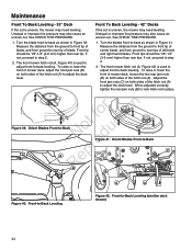
... is used to adjust front-to step 2. 2. If not, proceed to -back leveling. Front-to -back as shown in Figure 39. Front To Back Leveling - 42" Decks If the cut is uneven, the mower may need leveling. Turn the blades front-to -Back Leveling (simlilar deck shown) 34 To raise or...step 2. 2. If not, proceed to rear tips of center blade, and from the ground to front tip of the hitch rod (A) to -Back Leveling Figure 42. See CHECK TIRE PRESSURE. 1. Maintenance Front To Back Leveling - 33" Deck If the cut is uneven, the mower may need leveling. Unequal or improper tire...
... is used to adjust front-to step 2. 2. If not, proceed to -back leveling. Front-to -back as shown in Figure 39. Front To Back Leveling - 42" Decks If the cut is uneven, the mower may need leveling. Turn the blades front-to -Back Leveling (simlilar deck shown) 34 To raise or...step 2. 2. If not, proceed to rear tips of center blade, and from the ground to front tip of the hitch rod (A) to -Back Leveling Figure 42. See CHECK TIRE PRESSURE. 1. Maintenance Front To Back Leveling - 33" Deck If the cut is uneven, the mower may need leveling. Unequal or improper tire...
Operater's Manual
Page 36
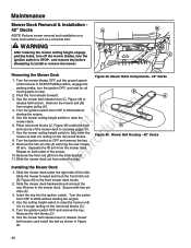
.... u 7. Remove the hair pin clip (A) securing the rear mower r lift arm. Mower Belt Routing - 42" Decks R Installing the Mower Deck A 1. Secure with hair pin clips (A). 3. Mower Hitch Components - 42" Decks 1. t c 6. Turn the ignition switch to the front mower deck hooks. 2. o 9. p 10...deck under the rider. B C Removing the Mower Deck Figure 45. Pivot the front wheels forward. 3. Maintenance Mower Deck Removal & Installation - 42" Decks A NOTE: Perform mower removal and installation on both sides of the mower. Remove the hitch rod (B) from under the right side ...
.... u 7. Remove the hair pin clip (A) securing the rear mower r lift arm. Mower Belt Routing - 42" Decks R Installing the Mower Deck A 1. Secure with hair pin clips (A). 3. Mower Hitch Components - 42" Decks 1. t c 6. Turn the ignition switch to the front mower deck hooks. 2. o 9. p 10...deck under the rider. B C Removing the Mower Deck Figure 45. Pivot the front wheels forward. 3. Maintenance Mower Deck Removal & Installation - 42" Decks A NOTE: Perform mower removal and installation on both sides of the mower. Remove the hitch rod (B) from under the right side ...

Operater's Manual
Page 37
Remove the key. ot uc Mower Drive Belt Replacement - 42" Decks N d 1. Remove the belt from the spark plug. Park the rider on a level surface. A 3. Disengage the PTO, turn off the engine, set the ground speed ... and Installation'. Refer to release belt tension and remove the mower drive belt (B) from the e PTO pulley (B). Remove the key. Figure 47. Mower Belt Routing - 42" Decks Note: It is not necessary to stop. Disengage the PTO, turn off the engine, set the ground speed control o levers to START/PARK, and...
Remove the key. ot uc Mower Drive Belt Replacement - 42" Decks N d 1. Remove the belt from the spark plug. Park the rider on a level surface. A 3. Disengage the PTO, turn off the engine, set the ground speed ... and Installation'. Refer to release belt tension and remove the mower drive belt (B) from the e PTO pulley (B). Remove the key. Figure 47. Mower Belt Routing - 42" Decks Note: It is not necessary to stop. Disengage the PTO, turn off the engine, set the ground speed control o levers to START/PARK, and...
Operater's Manual
Page 42
... supplied, is warranted for the periods of all material respects to the owner. Category C = 250 hours, Category B = 500 hours, Category A = 1000 hours en 381535 (Rev--) 42 Briggs & Stratton Emissions Control Warranty Provisions The following categories are specific provisions relative to 25 hours per year. Catalyst System N d Catalytic converter Exhaust...
... supplied, is warranted for the periods of all material respects to the owner. Category C = 250 hours, Category B = 500 hours, Category A = 1000 hours en 381535 (Rev--) 42 Briggs & Stratton Emissions Control Warranty Provisions The following categories are specific provisions relative to 25 hours per year. Catalyst System N d Catalytic converter Exhaust...
Parts Manual
Page 3
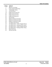
... Group 50" Mower Deck - Clutch & Support Group 50" Mower Deck - Housing & Arbor Group Electrical Group Wiring Schematic Table Of Contents HYDRO DRIVE ZTR 33", 42" & 50" 150Z SERIES 3 Manual No. 7006269 TP 400-5417-E-HZ-N PAGE 4 6 10 14 18 22 26 30 32 34 36 38 40 44 46 48 50 52... Group Controls Group Engine Group (18.5 H.P.) Engine Group (20 H.P.) Engine Group (21 H.P.) Engine Group (26 H.P.) Decal Group Mower Lift Group (33" Deck) Mower Lift Group (42" Deck) Mower Lift Group (50" Deck) 33" Mower Deck Group...
... Group 50" Mower Deck - Clutch & Support Group 50" Mower Deck - Housing & Arbor Group Electrical Group Wiring Schematic Table Of Contents HYDRO DRIVE ZTR 33", 42" & 50" 150Z SERIES 3 Manual No. 7006269 TP 400-5417-E-HZ-N PAGE 4 6 10 14 18 22 26 30 32 34 36 38 40 44 46 48 50 52... Group Controls Group Engine Group (18.5 H.P.) Engine Group (20 H.P.) Engine Group (21 H.P.) Engine Group (26 H.P.) Decal Group Mower Lift Group (33" Deck) Mower Lift Group (42" Deck) Mower Lift Group (50" Deck) 33" Mower Deck Group...

Parts Manual
Page 4
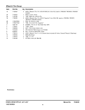
Wheel & Tire Group Manual No. 7006269 HYDRO DRIVE ZTR 33", 42" & 50" 4 150Z SERIES
Wheel & Tire Group Manual No. 7006269 HYDRO DRIVE ZTR 33", 42" & 50" 4 150Z SERIES
Parts Manual
Page 5
... & Tire 11 x 4-5 (Caster) (also includes Air Valve, Grease Fitting & 2 Bushings) 1 RIM w/Bushings 2 TIRE, 11 x 4-5 1 FITTING, Lube (45° 8Mx1M) Footnotes: HYDRO DRIVE ZTR 33", 42" & 50" 150Z SERIES 5 Manual No. 7006269 Wheel & Tire Group Item 1A 2A 3A 1B 2B 3B 4 5 6 7 8 9 10 11 12 Part No 7102822 7102823 7101565 1726383 1734878SM 1734877SM...
... & Tire 11 x 4-5 (Caster) (also includes Air Valve, Grease Fitting & 2 Bushings) 1 RIM w/Bushings 2 TIRE, 11 x 4-5 1 FITTING, Lube (45° 8Mx1M) Footnotes: HYDRO DRIVE ZTR 33", 42" & 50" 150Z SERIES 5 Manual No. 7006269 Wheel & Tire Group Item 1A 2A 3A 1B 2B 3B 4 5 6 7 8 9 10 11 12 Part No 7102822 7102823 7101565 1726383 1734878SM 1734877SM...
Parts Manual
Page 7
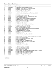
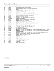
... x 3/4" Hex Flange Lock, Black 4 BOLT, 5/16-18 x 1" Hex Flange Lock YZ 1 PAD, Footrest RH Black Vinyl w/Adhesive Footnotes: HYDRO DRIVE ZTR 33", 42" & 50" 150Z SERIES 7 Manual No. 7006269 Black 4 WASHER, .75 ID x 1.60 OD x .05 Thick Flat (Black) 2 KLIPRING, External for .750 Dia. Black 2 BOLT...SCREW, 5/16-18 x 3/4" Hex Flange Lock Dog Point 1 SCREEN, Deck Top 3 RIVET, .188 x .617 Large Flange 1 WELDMENT, Frame - 33" ZT 1 WELDMENT, Frame - 42" & 50" ZT 1 SUPPORT, Seat Deck, ZTS - x .11 Thick, Black 1 NUT, Hex Flange 5/8-11 Two Way Lock, Yellow 1 BRACKET, Footrest Support, Black 2 SCREW,...
... x 3/4" Hex Flange Lock, Black 4 BOLT, 5/16-18 x 1" Hex Flange Lock YZ 1 PAD, Footrest RH Black Vinyl w/Adhesive Footnotes: HYDRO DRIVE ZTR 33", 42" & 50" 150Z SERIES 7 Manual No. 7006269 Black 4 WASHER, .75 ID x 1.60 OD x .05 Thick Flat (Black) 2 KLIPRING, External for .750 Dia. Black 2 BOLT...SCREW, 5/16-18 x 3/4" Hex Flange Lock Dog Point 1 SCREEN, Deck Top 3 RIVET, .188 x .617 Large Flange 1 WELDMENT, Frame - 33" ZT 1 WELDMENT, Frame - 42" & 50" ZT 1 SUPPORT, Seat Deck, ZTS - x .11 Thick, Black 1 NUT, Hex Flange 5/8-11 Two Way Lock, Yellow 1 BRACKET, Footrest Support, Black 2 SCREW,...
Parts Manual
Page 9
...) 1 BUSHING, Fuel 1 ELBOW, Gas Tank 1 FUEL CAP, Non-Vented, 12" Tether 1 ASSY, Elbow/Pick-Up Tube 1 GROMMET 1 VENT, Remote w/Valve Footnotes: HYDRO DRIVE ZTR 33", 42" & 50" 150Z SERIES 9 Manual No. 7006269 x 1.50 O.D. Black 1 SCREW, 3/8-16 x 1-1/4" Hex Head Cap, GR5, Black 1 PUSH NUT, .375 Dia. cap, pickup tube, bushing & elbow) (was 1715962A...
...) 1 BUSHING, Fuel 1 ELBOW, Gas Tank 1 FUEL CAP, Non-Vented, 12" Tether 1 ASSY, Elbow/Pick-Up Tube 1 GROMMET 1 VENT, Remote w/Valve Footnotes: HYDRO DRIVE ZTR 33", 42" & 50" 150Z SERIES 9 Manual No. 7006269 x 1.50 O.D. Black 1 SCREW, 3/8-16 x 1-1/4" Hex Head Cap, GR5, Black 1 PUSH NUT, .375 Dia. cap, pickup tube, bushing & elbow) (was 1715962A...
Parts Manual
Page 11
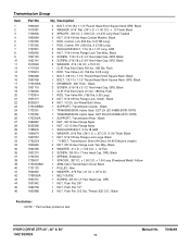
... O.D. x .87 O.D.) 1 BELT GUIDE 1 SCREW, 3/8-16 x 2" Hex Head Cap, GR5 1 NUT, Push Pal, 3/8" 1 NUT, Push Pal, 1/2" 2 NUT, Push Pal .312 Dia. HYDRO DRIVE ZTR 33", 42" & 50" 150Z SERIES 11 Manual No. 7006269 Rod) 1 ROD, Tow Valve LH (.156 Dia. 5.05 Long) 1 BOLT, 3/8-16 x 1-1/4" Round Head Short Square Neck, Black 1 BOLT, 1/2-13 x 1-1/2" Round... 16 17 18 19 20 21 22 23 24 25 26 27 28 29 30 31 33 34 35 36 37 38 39 40 41 42 43 44 45 46 Part No 1960223 1919381 1703900 1960684 1727555 1727556 1727831 1930650 1927120 1923141 1919326 1717024 1733913 1960268 1960758 1733305A 1921719 1725550 1733914...
... O.D. x .87 O.D.) 1 BELT GUIDE 1 SCREW, 3/8-16 x 2" Hex Head Cap, GR5 1 NUT, Push Pal, 3/8" 1 NUT, Push Pal, 1/2" 2 NUT, Push Pal .312 Dia. HYDRO DRIVE ZTR 33", 42" & 50" 150Z SERIES 11 Manual No. 7006269 Rod) 1 ROD, Tow Valve LH (.156 Dia. 5.05 Long) 1 BOLT, 3/8-16 x 1-1/4" Round Head Short Square Neck, Black 1 BOLT, 1/2-13 x 1-1/2" Round... 16 17 18 19 20 21 22 23 24 25 26 27 28 29 30 31 33 34 35 36 37 38 39 40 41 42 43 44 45 46 Part No 1960223 1919381 1703900 1960684 1727555 1727556 1727831 1930650 1927120 1923141 1919326 1717024 1733913 1960268 1960758 1733305A 1921719 1725550 1733914...
Parts Manual
Page 13
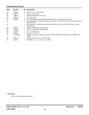
... Transmission (Hydro- Control Arm 1 SPRING, Extension (Used on belt. Gear #51901)) 1 GEAR, Parking Brake, Transmission 1 CLIP, E Transmission Parking Brake 1 KIT, L.H. HYDRO DRIVE ZTR 33", 42" & 50" 150Z SERIES 13 Manual No. 7006269 x .132 Flat Footnotes: NOTE: * Part number printed on Hydro-Gear P/N ZC-AHBB-2A7B-1DPX and ZC-AHBB-2A7B- 1DPX) 1 SCREW...
... Transmission (Hydro- Control Arm 1 SPRING, Extension (Used on belt. Gear #51901)) 1 GEAR, Parking Brake, Transmission 1 CLIP, E Transmission Parking Brake 1 KIT, L.H. HYDRO DRIVE ZTR 33", 42" & 50" 150Z SERIES 13 Manual No. 7006269 x .132 Flat Footnotes: NOTE: * Part number printed on Hydro-Gear P/N ZC-AHBB-2A7B-1DPX and ZC-AHBB-2A7B- 1DPX) 1 SCREW...
Parts Manual
Page 15
..., 5/16-18 Hex Lock Esna Light 2 WELDMENT, Pivot Control 4 SCREW, 5/16-18 x 1-1/2" Hex Head Cap, GR5, Black 2 SHOCK ABSORBER Footnotes: HYDRO DRIVE ZTR 33", 42" & 50" 150Z SERIES 15 Manual No. 7006269 x 1.00 O.D. ZT (5/16-18 thread) 1 ROD, Manual Parking Brake (1/4-20 threads) 1 BRACKET, Dual Brake 1 SPRING, Extension 1 SPRING, Compression... 19 20 21 22 23 24 25 26 27 28 29 30 31 32 33 34 35 36 37 38 39 40 41 42 43 44 Part No 1726410 1727796A 1960686 1720452BM 1919381 1960086 1917356 1727926A 1727927A 1931338 1931335 1727663BM 1727919 1728010A 1728009A 7300992BM 7091298 7015761 1960027...
..., 5/16-18 Hex Lock Esna Light 2 WELDMENT, Pivot Control 4 SCREW, 5/16-18 x 1-1/2" Hex Head Cap, GR5, Black 2 SHOCK ABSORBER Footnotes: HYDRO DRIVE ZTR 33", 42" & 50" 150Z SERIES 15 Manual No. 7006269 x 1.00 O.D. ZT (5/16-18 thread) 1 ROD, Manual Parking Brake (1/4-20 threads) 1 BRACKET, Dual Brake 1 SPRING, Extension 1 SPRING, Compression... 19 20 21 22 23 24 25 26 27 28 29 30 31 32 33 34 35 36 37 38 39 40 41 42 43 44 Part No 1726410 1727796A 1960686 1720452BM 1919381 1960086 1917356 1727926A 1727927A 1931338 1931335 1727663BM 1727919 1728010A 1728009A 7300992BM 7091298 7015761 1960027...
Parts Manual
Page 17
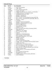
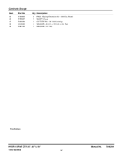
x .75 O.D.x .06, Flat 1 WASHER, 1/2" Flat Footnotes: HYDRO DRIVE ZTR 33", 42" & 50" 150Z SERIES 17 Manual No. 7006269 Shaft) 1 SHAFT, Cross 1 COTTER PIN, 1/4", Self-Locking 1 WASHER, .34 I.D. Controls Group Item 45 46 47 48 49 Part No 1703805 1725927 7023590 1919326 7091192 Qty Description 2 RING, Klipring Extension (for .500 Dia.
x .75 O.D.x .06, Flat 1 WASHER, 1/2" Flat Footnotes: HYDRO DRIVE ZTR 33", 42" & 50" 150Z SERIES 17 Manual No. 7006269 Shaft) 1 SHAFT, Cross 1 COTTER PIN, 1/4", Self-Locking 1 WASHER, .34 I.D. Controls Group Item 45 46 47 48 49 Part No 1703805 1725927 7023590 1919326 7091192 Qty Description 2 RING, Klipring Extension (for .500 Dia.
Parts Manual
Page 19
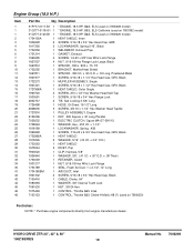
...-SN11S WASHER, Hex, .453 I .D. x 1-1/2" LOCKWASHER, Spring, .438 SCREW, 7/16-20 x 2-3/4" Hex Head Cap, GR5, Black HEAT SHIELD WASHER, 5/16" (.34 I .D. HYDRO DRIVE ZTR 33", 42" & 50" 150Z SERIES 19 Manual No. 7006269 Engine Group (18.5 H.P.) Item 1 1 1 2 3 4 5 6 7 8 9 10 11 12 13 14 15 16 17 18 19 20 21 22 23 24 25... 26 27 28 29 30 31 32 33 34 35 41 42 43 44 45 46 46 Part No Qty Description 31P777-0117-B1 1 31Q777-0118...
...-SN11S WASHER, Hex, .453 I .D. x 1-1/2" LOCKWASHER, Spring, .438 SCREW, 7/16-20 x 2-3/4" Hex Head Cap, GR5, Black HEAT SHIELD WASHER, 5/16" (.34 I .D. HYDRO DRIVE ZTR 33", 42" & 50" 150Z SERIES 19 Manual No. 7006269 Engine Group (18.5 H.P.) Item 1 1 1 2 3 4 5 6 7 8 9 10 11 12 13 14 15 16 17 18 19 20 21 22 23 24 25... 26 27 28 29 30 31 32 33 34 35 41 42 43 44 45 46 46 Part No Qty Description 31P777-0117-B1 1 31Q777-0118...
Parts Manual
Page 21
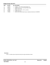
x 19-1/2" Low Perm 2 CLAMP, Fuel Hose 1 INSULATION, Muffler Shield (Used on models after Serial No. 2013245844) Footnotes: NOTE: * Purchase engine components directly from engine manufacturer dealer. Engine Group (18.5 H.P.) Item 47 48 49 50 51 52 Part No 7090999 7091195 7100529 1734995 7012222 1734062 Qty Description 2 SCREW, 1/4-20 x 5/8" Pan Head Taptite Torx 1 SCREW, #10-16 x 3/4" Pan Head Taptite Combo 1 KNOB, Throttle, Red 1 HOSE, Fuel, 1/4" I.D. HYDRO DRIVE ZTR 33", 42" & 50" 150Z SERIES 21 Manual No. 7006269
x 19-1/2" Low Perm 2 CLAMP, Fuel Hose 1 INSULATION, Muffler Shield (Used on models after Serial No. 2013245844) Footnotes: NOTE: * Purchase engine components directly from engine manufacturer dealer. Engine Group (18.5 H.P.) Item 47 48 49 50 51 52 Part No 7090999 7091195 7100529 1734995 7012222 1734062 Qty Description 2 SCREW, 1/4-20 x 5/8" Pan Head Taptite Torx 1 SCREW, #10-16 x 3/4" Pan Head Taptite Combo 1 KNOB, Throttle, Red 1 HOSE, Fuel, 1/4" I.D. HYDRO DRIVE ZTR 33", 42" & 50" 150Z SERIES 21 Manual No. 7006269
