
Operater's Manual
Page 11
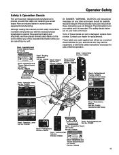
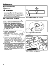
...r n Part No. 1726638 Decal - Contact your dealer for mowing . 1704277 173xxxx safe, effective operation. Amputation and Thrown Objects Hazard (33" Decks) Part No. 7101665 DANGER Amputation and thrown objects hazard Keep hands and feet away from rotating blades, stay clear of this important...key (it is in its proper place. 7101665 Decal - Move ground speed levers to SLOW. 4. Amputation and Thrown Objects Hazard (33" Decks) Part No. 7101665 11 These labels are hot and can result when equipment manufacturing. Amputation and Thrown Objects Hazard (42"...
...r n Part No. 1726638 Decal - Contact your dealer for mowing . 1704277 173xxxx safe, effective operation. Amputation and Thrown Objects Hazard (33" Decks) Part No. 7101665 DANGER Amputation and thrown objects hazard Keep hands and feet away from rotating blades, stay clear of this important...key (it is in its proper place. 7101665 Decal - Move ground speed levers to SLOW. 4. Amputation and Thrown Objects Hazard (33" Decks) Part No. 7101665 11 These labels are hot and can result when equipment manufacturing. Amputation and Thrown Objects Hazard (42"...

Operater's Manual
Page 22
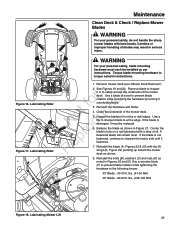
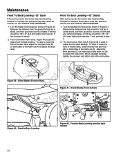
... parts should be oiled where contact is made with other parts. Remember to wipe fittings and r n surfaces clean both before and after lubrication. Mower Lubrication - 33" Deck 22 Keep oil and grease off belts and pulleys. Arbor Lubrication RNeprod(3-Blade Model Shown, All Models Similar) Figure 13. Use automotive-type lithium...
... parts should be oiled where contact is made with other parts. Remember to wipe fittings and r n surfaces clean both before and after lubrication. Mower Lubrication - 33" Deck 22 Keep oil and grease off belts and pulleys. Arbor Lubrication RNeprod(3-Blade Model Shown, All Models Similar) Figure 13. Use automotive-type lithium...
Operater's Manual
Page 23
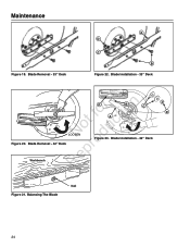
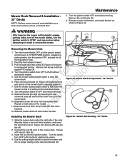
... mower deck. Reinstall the bolts (B), washers (C) and nuts (D) as per instructions. Lubricating Rider Figure 17. e 7. Figure 16. Torque blade mounting hardware to the following torque: 33" Blade - 30-40 ft. Remove mower deck (see "Mower Deck Removal"). 2. t 4. Clean the underside of the mower deck. N d6. Balance the blade as shown. 8. Reinstall...
... mower deck. Reinstall the bolts (B), washers (C) and nuts (D) as per instructions. Lubricating Rider Figure 17. e 7. Figure 16. Torque blade mounting hardware to the following torque: 33" Blade - 30-40 ft. Remove mower deck (see "Mower Deck Removal"). 2. t 4. Clean the underside of the mower deck. N d6. Balance the blade as shown. 8. Reinstall...
Operater's Manual
Page 24
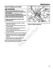
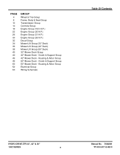
Blade Installation - 42" Deck epr Workbench R Blade Removal.epsf D Nail Figure 21. Balancing The Blade Blade Balancing.eps 24 Blade Removal - 33" Deck A D C B Figure 22. Blade Installation - 33" Deck r n F E C fo tio A ot uc LOOSEN N od Figure 20. Blade Removal - 42" Deck Figure 23. Maintenance Figure 19.
Blade Installation - 42" Deck epr Workbench R Blade Removal.epsf D Nail Figure 21. Balancing The Blade Blade Balancing.eps 24 Blade Removal - 33" Deck A D C B Figure 22. Blade Installation - 33" Deck r n F E C fo tio A ot uc LOOSEN N od Figure 20. Blade Removal - 42" Deck Figure 23. Maintenance Figure 19.
Operater's Manual
Page 25
If not done in this order, the positive terminal can be shorted to the frame by a tool. Clean the battery terminals and cable ends with 33" decks, the battery is mounted Repr on the right side of baking soda and water. N d 7. Engine Compartment 2. o Note: On models with a fo tio wire brush ...
If not done in this order, the positive terminal can be shorted to the frame by a tool. Clean the battery terminals and cable ends with 33" decks, the battery is mounted Repr on the right side of baking soda and water. N d 7. Engine Compartment 2. o Note: On models with a fo tio wire brush ...
Operater's Manual
Page 32
...proceed to Front To Back Leveling. With the mower installed, place the rider on the right and left rear sides of the blade (A, Figure 33) and the ground (B). Check for r n all moving parts to stop . When complete, tighten the jam nuts against the trunnion to -Side... Adjustment 32 Side to mid position. Set the cutting height to Side Leveling - 33" Decks Figure 33. Measure the distance between the r measurements on each side, proceed to step 6. Figure 35. Remove ignition key, then disconnect the spark...
...proceed to Front To Back Leveling. With the mower installed, place the rider on the right and left rear sides of the blade (A, Figure 33) and the ground (B). Check for r n all moving parts to stop . When complete, tighten the jam nuts against the trunnion to -Side... Adjustment 32 Side to mid position. Set the cutting height to Side Leveling - 33" Decks Figure 33. Measure the distance between the r measurements on each side, proceed to step 6. Figure 35. Remove ignition key, then disconnect the spark...

Operater's Manual
Page 33
... rods (A) and trunnion (B) on a smooth, level surface such as a concrete floor. See r n CHECK TIRE PRESSURE. r 6. Set the cutting height to -Side Adjustment (similar deck shown) 33 Check the tire pressures. Arrange the mower blades so that they are pointing from the spark plug. With the mower installed, place the rider on...
... rods (A) and trunnion (B) on a smooth, level surface such as a concrete floor. See r n CHECK TIRE PRESSURE. r 6. Set the cutting height to -Side Adjustment (similar deck shown) 33 Check the tire pressures. Arrange the mower blades so that they are pointing from the spark plug. With the mower installed, place the rider on...
Operater's Manual
Page 34
... nuts (B) to rear tips of center blade, and from ground to adjust the deck level. Orient Blades Front-to step 2. 2. Maintenance Front To Back Leveling - 33" Deck If the cut is uneven, the mower may need leveling. Unequal or improper tire pressure may also cause an uneven cut . Front tip should...
... nuts (B) to rear tips of center blade, and from ground to adjust the deck level. Orient Blades Front-to step 2. 2. Maintenance Front To Back Leveling - 33" Deck If the cut is uneven, the mower may need leveling. Unequal or improper tire pressure may also cause an uneven cut . Front tip should...
Operater's Manual
Page 35
...pin clips (A) securing the rear r mower lift arms (B) and the front hitch rod (C) to stop. 2. Mower Hitch Components - 33" Decks A B 12. Mower Belt Routing - 33" Decks 35 Separate the rear lift arms from the front hitch R brackets. Remove the front hitch rod (C) from the mower deck.... Use the mower cutting height switch to OFF and remove the key. Turn the ignition switch to raise the mower deck. Mower Deck Removal & Installation 33" Decks NOTE: Perform mower removal and installation on a hard, level surface such as shown in Figure 44. t c 6. e Repeat on the ...
...pin clips (A) securing the rear r mower lift arms (B) and the front hitch rod (C) to stop. 2. Mower Hitch Components - 33" Decks A B 12. Mower Belt Routing - 33" Decks 35 Separate the rear lift arms from the front hitch R brackets. Remove the front hitch rod (C) from the mower deck.... Use the mower cutting height switch to OFF and remove the key. Turn the ignition switch to raise the mower deck. Mower Deck Removal & Installation 33" Decks NOTE: Perform mower removal and installation on a hard, level surface such as shown in Figure 44. t c 6. e Repeat on the ...

Operater's Manual
Page 37
...arm (C, Figure 48) to completely remove the r n belt. Install the new belt (A) as shown in Figure 48. 37 Maintenance B A C Mower Drive Belt Replacement - 33" Decks 1. ot uc Mower Drive Belt Replacement - 42" Decks N d 1. p 2. Disengage the PTO, turn the ignition switch OFF, and allow all moving parts to ... engine, set the ground speed control levers to START/PARK, and set the parking brake r lever to stop. Mower Belt Routing - 33" Decks 2. Figure 47. Remove ignition key, then disconnect the spark plug wire and fasten it away from the remaining deck pulleys.
...arm (C, Figure 48) to completely remove the r n belt. Install the new belt (A) as shown in Figure 48. 37 Maintenance B A C Mower Drive Belt Replacement - 33" Decks 1. ot uc Mower Drive Belt Replacement - 42" Decks N d 1. p 2. Disengage the PTO, turn the ignition switch OFF, and allow all moving parts to ... engine, set the ground speed control levers to START/PARK, and set the parking brake r lever to stop. Mower Belt Routing - 33" Decks 2. Figure 47. Remove ignition key, then disconnect the spark plug wire and fasten it away from the remaining deck pulleys.
Parts Manual
Page 3
Clutch & Support Group 50" Mower Deck - Housing & Arbor Group Electrical Group Wiring Schematic Table Of Contents HYDRO DRIVE ZTR 33", 42" & 50" 150Z SERIES 3 Manual No. 7006269 TP 400-5417-E-HZ-N Clutch & Support Group 42" Mower Deck - PAGE 4 6 10 14 18 22 26 30 32 34 ... & Seat Group Transmission Group Controls Group Engine Group (18.5 H.P.) Engine Group (20 H.P.) Engine Group (21 H.P.) Engine Group (26 H.P.) Decal Group Mower Lift Group (33" Deck) Mower Lift Group (42" Deck) Mower Lift Group (50" Deck) 33" Mower Deck Group 42" Mower Deck - Housing & Arbor Group 50" Mower Deck -
Clutch & Support Group 50" Mower Deck - Housing & Arbor Group Electrical Group Wiring Schematic Table Of Contents HYDRO DRIVE ZTR 33", 42" & 50" 150Z SERIES 3 Manual No. 7006269 TP 400-5417-E-HZ-N Clutch & Support Group 42" Mower Deck - PAGE 4 6 10 14 18 22 26 30 32 34 ... & Seat Group Transmission Group Controls Group Engine Group (18.5 H.P.) Engine Group (20 H.P.) Engine Group (21 H.P.) Engine Group (26 H.P.) Decal Group Mower Lift Group (33" Deck) Mower Lift Group (42" Deck) Mower Lift Group (50" Deck) 33" Mower Deck Group 42" Mower Deck - Housing & Arbor Group 50" Mower Deck -

Parts Manual
Page 4
Wheel & Tire Group Manual No. 7006269 HYDRO DRIVE ZTR 33", 42" & 50" 4 150Z SERIES
Wheel & Tire Group Manual No. 7006269 HYDRO DRIVE ZTR 33", 42" & 50" 4 150Z SERIES
Parts Manual
Page 5
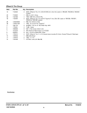
..., Wheel & Tire 11 x 4-5 (Caster) (also includes Air Valve, Grease Fitting & 2 Bushings) 1 RIM w/Bushings 2 TIRE, 11 x 4-5 1 FITTING, Lube (45° 8Mx1M) Footnotes: HYDRO DRIVE ZTR 33", 42" & 50" 150Z SERIES 5 Manual No. 7006269 Wheel & Tire Group Item 1A 2A 3A 1B 2B 3B 4 5 6 7 8 9 10 11 12 Part No 7102822 7102823 7101565 1726383 1734878SM...
..., Wheel & Tire 11 x 4-5 (Caster) (also includes Air Valve, Grease Fitting & 2 Bushings) 1 RIM w/Bushings 2 TIRE, 11 x 4-5 1 FITTING, Lube (45° 8Mx1M) Footnotes: HYDRO DRIVE ZTR 33", 42" & 50" 150Z SERIES 5 Manual No. 7006269 Wheel & Tire Group Item 1A 2A 3A 1B 2B 3B 4 5 6 7 8 9 10 11 12 Part No 7102822 7102823 7101565 1726383 1734878SM...
Parts Manual
Page 7
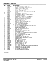
..., Black 6 SCREW, 1/4-20 x 3/4" Hex Flange Lock, Black 4 BOLT, 5/16-18 x 1" Hex Flange Lock YZ 1 PAD, Footrest RH Black Vinyl w/Adhesive Footnotes: HYDRO DRIVE ZTR 33", 42" & 50" 150Z SERIES 7 Manual No. 7006269 Red 1 PLATE, Control, ZTS - x 1.75 O.D. Black 1 SEAT DECK, Red Poly, ZTS - items 6A & 6B) 4 BUSHING 3 GREASE FITTING, 1/4" ...4 5 6 6A 6B 7 8 9 10 11 12 13 14 15 16 17 18 19 20 21 22 23 24 25 26 27 28 29 30 31 32 33 33 34 35 36 36 37 37 38 39 Part No 1733448BM 1960160 1611710 1734135 1730186 1733426A 2176440 1704314 1733571 1960687 2860744 1960035 2860646 1733304A 1930601...
..., Black 6 SCREW, 1/4-20 x 3/4" Hex Flange Lock, Black 4 BOLT, 5/16-18 x 1" Hex Flange Lock YZ 1 PAD, Footrest RH Black Vinyl w/Adhesive Footnotes: HYDRO DRIVE ZTR 33", 42" & 50" 150Z SERIES 7 Manual No. 7006269 Red 1 PLATE, Control, ZTS - x 1.75 O.D. Black 1 SEAT DECK, Red Poly, ZTS - items 6A & 6B) 4 BUSHING 3 GREASE FITTING, 1/4" ...4 5 6 6A 6B 7 8 9 10 11 12 13 14 15 16 17 18 19 20 21 22 23 24 25 26 27 28 29 30 31 32 33 33 34 35 36 36 37 37 38 39 Part No 1733448BM 1960160 1611710 1734135 1730186 1733426A 2176440 1704314 1733571 1960687 2860744 1960035 2860646 1733304A 1930601...
Parts Manual
Page 9
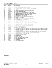
... (Vented) 1 BUSHING, Fuel 1 ELBOW, Gas Tank 1 FUEL CAP, Non-Vented, 12" Tether 1 ASSY, Elbow/Pick-Up Tube 1 GROMMET 1 VENT, Remote w/Valve Footnotes: HYDRO DRIVE ZTR 33", 42" & 50" 150Z SERIES 9 Manual No. 7006269 Black 1 SCREW, 3/8-16 x 1-1/4" Hex Head Cap, GR5, Black 1 PUSH NUT, .375 Dia.
... (Vented) 1 BUSHING, Fuel 1 ELBOW, Gas Tank 1 FUEL CAP, Non-Vented, 12" Tether 1 ASSY, Elbow/Pick-Up Tube 1 GROMMET 1 VENT, Remote w/Valve Footnotes: HYDRO DRIVE ZTR 33", 42" & 50" 150Z SERIES 9 Manual No. 7006269 Black 1 SCREW, 3/8-16 x 1-1/4" Hex Head Cap, GR5, Black 1 PUSH NUT, .375 Dia.
Parts Manual
Page 11
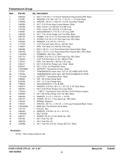
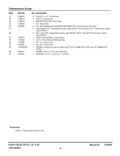
... 1 TRANSMISSION, Hydro Gear EZT LH (ZC-AHBB-2A7B-1DPX) 1 TRANSMISSION, Hydro Gear EZT RH (ZC-DHBB-2A7C-1DPX) 1 SUPPORT, Transmission Rear - HYDRO DRIVE ZTR 33", 42" & 50" 150Z SERIES 11 Manual No. 7006269 Transmission Group Item 1 2 3 4 5 6 7 8 9 10 11 13 14 15 16 17 18 19 20 21 22 23 24 25 26... 27 28 29 30 31 33 34 35 36 37 38 39 40 41 42 43 44 45 46 Part No 1960223 1919381 1703900 1960684 1727555...
... 1 TRANSMISSION, Hydro Gear EZT LH (ZC-AHBB-2A7B-1DPX) 1 TRANSMISSION, Hydro Gear EZT RH (ZC-DHBB-2A7C-1DPX) 1 SUPPORT, Transmission Rear - HYDRO DRIVE ZTR 33", 42" & 50" 150Z SERIES 11 Manual No. 7006269 Transmission Group Item 1 2 3 4 5 6 7 8 9 10 11 13 14 15 16 17 18 19 20 21 22 23 24 25 26... 27 28 29 30 31 33 34 35 36 37 38 39 40 41 42 43 44 45 46 Part No 1960223 1919381 1703900 1960684 1727555...
Parts Manual
Page 13
..., Parking Brake, Transmission 1 CLIP, E Transmission Parking Brake 1 KIT, L.H. Gear #70314)) 2 NUT, Axle, EZT Transmission (Hydro-Gear #51901) (NUT, Axle, EZT Transmission (Hydro- HYDRO DRIVE ZTR 33", 42" & 50" 150Z SERIES 13 Manual No. 7006269 x 1.25 O.D.
..., Parking Brake, Transmission 1 CLIP, E Transmission Parking Brake 1 KIT, L.H. Gear #70314)) 2 NUT, Axle, EZT Transmission (Hydro-Gear #51901) (NUT, Axle, EZT Transmission (Hydro- HYDRO DRIVE ZTR 33", 42" & 50" 150Z SERIES 13 Manual No. 7006269 x 1.25 O.D.
Parts Manual
Page 15
... 4 NUT, 5/16-18 Hex Lock Esna Light 2 WELDMENT, Pivot Control 4 SCREW, 5/16-18 x 1-1/2" Hex Head Cap, GR5, Black 2 SHOCK ABSORBER Footnotes: HYDRO DRIVE ZTR 33", 42" & 50" 150Z SERIES 15 Manual No. 7006269 x .13 Thick) Black 4 SCREW, 5/16-18 x 7/8" Truss Head Torx, Black 4 LOCKWASHER, Spring 5/16", Black 1 BRACKET, Tube Mount LH 1 BRACKET... Group Item 1 2 3 4 5 6 7 8 9 10 11 12 13 14 15 16 17 18 19 20 21 22 23 24 25 26 27 28 29 30 31 32 33 34 35 36 37 38 39 40 41 42 43 44 Part No 1726410 1727796A 1960686 1720452BM 1919381 1960086 1917356 1727926A 1727927A 1931338 1931335 1727663BM...
... 4 NUT, 5/16-18 Hex Lock Esna Light 2 WELDMENT, Pivot Control 4 SCREW, 5/16-18 x 1-1/2" Hex Head Cap, GR5, Black 2 SHOCK ABSORBER Footnotes: HYDRO DRIVE ZTR 33", 42" & 50" 150Z SERIES 15 Manual No. 7006269 x .13 Thick) Black 4 SCREW, 5/16-18 x 7/8" Truss Head Torx, Black 4 LOCKWASHER, Spring 5/16", Black 1 BRACKET, Tube Mount LH 1 BRACKET... Group Item 1 2 3 4 5 6 7 8 9 10 11 12 13 14 15 16 17 18 19 20 21 22 23 24 25 26 27 28 29 30 31 32 33 34 35 36 37 38 39 40 41 42 43 44 Part No 1726410 1727796A 1960686 1720452BM 1919381 1960086 1917356 1727926A 1727927A 1931338 1931335 1727663BM...
Parts Manual
Page 17
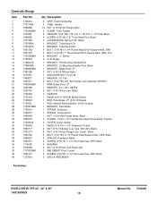
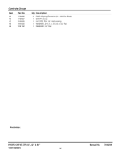
Controls Group Item 45 46 47 48 49 Part No 1703805 1725927 7023590 1919326 7091192 Qty Description 2 RING, Klipring Extension (for .500 Dia. x .75 O.D.x .06, Flat 1 WASHER, 1/2" Flat Footnotes: HYDRO DRIVE ZTR 33", 42" & 50" 150Z SERIES 17 Manual No. 7006269 Shaft) 1 SHAFT, Cross 1 COTTER PIN, 1/4", Self-Locking 1 WASHER, .34 I.D.
Controls Group Item 45 46 47 48 49 Part No 1703805 1725927 7023590 1919326 7091192 Qty Description 2 RING, Klipring Extension (for .500 Dia. x .75 O.D.x .06, Flat 1 WASHER, 1/2" Flat Footnotes: HYDRO DRIVE ZTR 33", 42" & 50" 150Z SERIES 17 Manual No. 7006269 Shaft) 1 SHAFT, Cross 1 COTTER PIN, 1/4", Self-Locking 1 WASHER, .34 I.D.
Parts Manual
Page 19
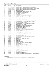
... CONTROL, Throttle B&S Intek CONTROL, Throttle B&S Choke-A-Matic (48.0") (used on 7800620) Footnotes: NOTE: * Purchase engine components directly from engine manufacturer dealer. HYDRO DRIVE ZTR 33", 42" & 50" 150Z SERIES 19 Manual No. 7006269 Engine Group (18.5 H.P.) Item 1 1 1 2 3 4 5 6 7 8 9 10 11 12 13 14 15 16 17 18 19 20 21 22 23 24... 25 26 27 28 29 30 31 32 33 34 35 41 42 43 44 45 46 46 Part No Qty Description 31P777-0117-B1 1 31Q777...
... CONTROL, Throttle B&S Intek CONTROL, Throttle B&S Choke-A-Matic (48.0") (used on 7800620) Footnotes: NOTE: * Purchase engine components directly from engine manufacturer dealer. HYDRO DRIVE ZTR 33", 42" & 50" 150Z SERIES 19 Manual No. 7006269 Engine Group (18.5 H.P.) Item 1 1 1 2 3 4 5 6 7 8 9 10 11 12 13 14 15 16 17 18 19 20 21 22 23 24... 25 26 27 28 29 30 31 32 33 34 35 41 42 43 44 45 46 46 Part No Qty Description 31P777-0117-B1 1 31Q777...