Operater's Manual
Page 10
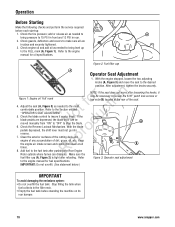
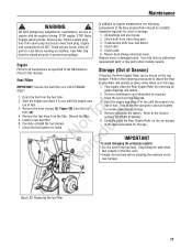
... 1). Figure 2: Fuel filler cap A Operator Seat Adjustment 1. After adjustment, tighten the knobs securely. Clean the exterior surfaces of the cutting deck and p engine of any accumulation of the seat. Stop filling the tank when fuel collects in place and securely tightened. 3. Keep the ... the rear of dirt, grass, oil, etc. Operation Before Starting Make the following checks and perform the service required before standing the machine on its rear bumper. 10 www.snapper.com Refer to the Section entitled t c "OPERATOR'S SEAT ADJUSTMENT". Check the tire pressure;
... 1). Figure 2: Fuel filler cap A Operator Seat Adjustment 1. After adjustment, tighten the knobs securely. Clean the exterior surfaces of the cutting deck and p engine of any accumulation of the seat. Stop filling the tank when fuel collects in place and securely tightened. 3. Keep the ... the rear of dirt, grass, oil, etc. Operation Before Starting Make the following checks and perform the service required before standing the machine on its rear bumper. 10 www.snapper.com Refer to the Section entitled t c "OPERATOR'S SEAT ADJUSTMENT". Check the tire pressure;
Operater's Manual
Page 19
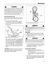
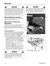
...brake for proper function: Engage the park brake, and push the machine. Blades must be closed securely to the section entitled "SERVICE BRAKE - Service Brake / Park Brake 1. Check the machine brake for proper function. Refer to prevent fuel spillage. Engine and components are not...must stop rotating in 3 seconds or less after moving the blade control lever to the deck. Fuel Filler Cap must be 1-1/4" but no less than 1". WARNING ! WARNING ! Refer do not operate the machine. SNAPPER dealer for tion A t c B No odu Figure 21: Removing the drive belt ...
...brake for proper function: Engage the park brake, and push the machine. Blades must be closed securely to the section entitled "SERVICE BRAKE - Service Brake / Park Brake 1. Check the machine brake for proper function. Refer to prevent fuel spillage. Engine and components are not...must stop rotating in 3 seconds or less after moving the blade control lever to the deck. Fuel Filler Cap must be 1-1/4" but no less than 1". WARNING ! WARNING ! Refer do not operate the machine. SNAPPER dealer for tion A t c B No odu Figure 21: Removing the drive belt ...
Operater's Manual
Page 21
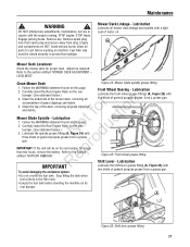
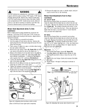
...debris. Follow the WARNING statement found on its rear bumper. DO NOT attempt any adjustments, maintenance, service or repairs with five shots of the deck, removing all accumulation of motor oil. Engage parking brake. Lubrication Lubricate all parts to prevent fuel ...grease fitting (A, Figure 24) with two shots of general purpose grease from a grease gun. Maintenance ! Remove key. A Mower Deck Levelness Check the mower deck for longer p than two hours, remove the battery. Mower Blade Spindle - WARNING ! r n 5. Carefully stand the Rear Engine...
...debris. Follow the WARNING statement found on its rear bumper. DO NOT attempt any adjustments, maintenance, service or repairs with five shots of the deck, removing all accumulation of motor oil. Engage parking brake. Lubrication Lubricate all parts to prevent fuel ...grease fitting (A, Figure 24) with two shots of general purpose grease from a grease gun. Maintenance ! Remove key. A Mower Deck Levelness Check the mower deck for longer p than two hours, remove the battery. Mower Blade Spindle - WARNING ! r n 5. Carefully stand the Rear Engine...
Operater's Manual
Page 23
...Storage (Out of Season) If desired, the Rear Engine Rider can be closed securely to run until the engine runs out of storage. IMPORTANT: Service the fuel filter on machine. Drain the fuel from plug. Install a new fuel filter. Remove and store the battery. Transmission shift lever and detent...the tank when B fuel collects in this manual. Remove spark plug wire from spark plug and secure away from the fuel tank. 2. Mower deck linkage and pivot areas. Start the engine and allow it to prevent fuel spillage. Remove the fuel lines from the fuel fo tio filter (A). ...
...Storage (Out of Season) If desired, the Rear Engine Rider can be closed securely to run until the engine runs out of storage. IMPORTANT: Service the fuel filter on machine. Drain the fuel from plug. Install a new fuel filter. Remove and store the battery. Transmission shift lever and detent...the tank when B fuel collects in this manual. Remove spark plug wire from spark plug and secure away from the fuel tank. 2. Mower deck linkage and pivot areas. Start the engine and allow it to prevent fuel spillage. Remove the fuel lines from the fuel fo tio filter (A). ...
Operater's Manual
Page 24
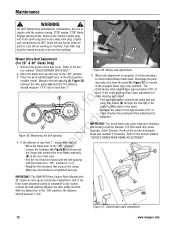
...should come to a stop the blades within 3 t c seconds any adjustments, maintenance, service or repairs with the adjustment procedure described above, take longer than 3-1/4", rotate the brake adjustment...NOT operate machine until blade brake is greater than 3 seconds to an authorized Snapper dealer. fo tio Blade Brake Adjustment The automatic Blade Brake should be achieved ...tighten the bolts securely. If the blade continues to decrease brake tension. 4. WARNING ! Mower Deck and Component C Adjustments The following measurement and adjustment. 1. Once blade is disengaged it is...
...should come to a stop the blades within 3 t c seconds any adjustments, maintenance, service or repairs with the adjustment procedure described above, take longer than 3-1/4", rotate the brake adjustment...NOT operate machine until blade brake is greater than 3 seconds to an authorized Snapper dealer. fo tio Blade Brake Adjustment The automatic Blade Brake should be achieved ...tighten the bolts securely. If the blade continues to decrease brake tension. 4. WARNING ! Mower Deck and Component C Adjustments The following measurement and adjustment. 1. Once blade is disengaged it is...
Operater's Manual
Page 25
... Remove the rear hanger chains (A, Figure 34). 2. tions on a smooth, level surface, side deck levelness. ceed to check front to -Rear Engage parking brake. DO NOT attempt any adjustments, maintenance, service or repairs with adjustment. STOP engine. Remove key. Fuel Filler Cap must be closed securely to ...If t c the measurement is obtained. o u side is still uneven, adjust side-to rest on machine. r 8. Engine and components are 30" Decks properly inflated and mowing is greater than the front. With the Rear Engine Rider on the eye-bolt to raise or lower the rear of...
... Remove the rear hanger chains (A, Figure 34). 2. tions on a smooth, level surface, side deck levelness. ceed to check front to -Rear Engage parking brake. DO NOT attempt any adjustments, maintenance, service or repairs with adjustment. STOP engine. Remove key. Fuel Filler Cap must be closed securely to ...If t c the measurement is obtained. o u side is still uneven, adjust side-to rest on machine. r 8. Engine and components are 30" Decks properly inflated and mowing is greater than the front. With the Rear Engine Rider on the eye-bolt to raise or lower the rear of...
Operater's Manual
Page 26
...less than 1". Recheck the cable for any adjustments, maintenance, service or repairs with the blade lever "ON", measures 1-1/4". C (B) to check Clutch/Brake Cable slack. IMPORTANT: The SNAPPER Rear Engine Rider Models with 33" decks do not require belt tension adjustment. Figure 36: Mower belt ...adjustment 2. Remove spark plug wire from spark plug and secure away from plug. Place the deck cutting height lever in the "ON" ...
...less than 1". Recheck the cable for any adjustments, maintenance, service or repairs with the blade lever "ON", measures 1-1/4". C (B) to check Clutch/Brake Cable slack. IMPORTANT: The SNAPPER Rear Engine Rider Models with 33" decks do not require belt tension adjustment. Figure 36: Mower belt ...adjustment 2. Remove spark plug wire from spark plug and secure away from plug. Place the deck cutting height lever in the "ON" ...
Operater's Manual
Page 29
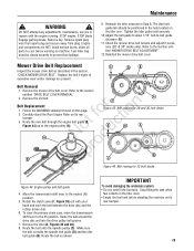
...its rear bumper. 3. Move the transmission shift lever to -belt guide clearance (E). 11. Check the mower drive belt tension and adjust if necessary (28" & 30" decks only). E D B Belt Removal 1. r n Belt Replacement 1. Make sure the belt is inside the spindle belt guide (D) and the idler belt guide (B). Engage ... WARNING ! Rotate the clutch yoke (F, Figure 39) out with the engine running. Remove key. Maintenance ! DO NOT attempt any adjustments, maintenance, service or repairs with your hand and work the belt between the drive disc and the rubber driven disc. 6.
...its rear bumper. 3. Move the transmission shift lever to -belt guide clearance (E). 11. Check the mower drive belt tension and adjust if necessary (28" & 30" decks only). E D B Belt Removal 1. r n Belt Replacement 1. Make sure the belt is inside the spindle belt guide (D) and the idler belt guide (B). Engage ... WARNING ! Rotate the clutch yoke (F, Figure 39) out with the engine running. Remove key. Maintenance ! DO NOT attempt any adjustments, maintenance, service or repairs with your hand and work the belt between the drive disc and the rubber driven disc. 6.
Operater's Manual
Page 33
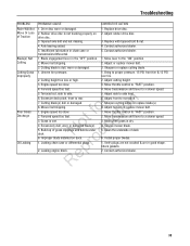
... cutting blade. 1. Move transmission shift lever to rear pitch. 7. Adjust or replace mower belt. 3. Leaking engine block. 5. Adjust front to a slower speed. 5. Service mower blade. 5. Clean the underside of deck. 6. Insufficient lubrication in chain case or transmission/differential. 1. Tapered axle bolt and nut missing. 4. o u 5. Rubber drive disc is wet. 4. Forward speed too...
... cutting blade. 1. Move transmission shift lever to rear pitch. 7. Adjust or replace mower belt. 3. Leaking engine block. 5. Adjust front to a slower speed. 5. Service mower blade. 5. Clean the underside of deck. 6. Insufficient lubrication in chain case or transmission/differential. 1. Tapered axle bolt and nut missing. 4. o u 5. Rubber drive disc is wet. 4. Forward speed too...
Operater's Manual
Page 36
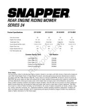
... RPM. ence is due to a variety of factors including, but not limited to -engine variability. This differ- www.snapper.com Net power values are taken with - Due to -engine variability. horsepower values are placed, the gas engine may ... 7 5-Spd Disc 1.0-4.6 / 0-1.9 12.5 344 7 5-Spd Disc 1.0-4.6 / 0-1.9 14.5 344 7 t c Common Service Parts Part Number o u Cutter Blade (28") N d Cutter Blade (30") Cutter Blade (33") o Cutting Deck Belt (28 and 30") r Cutting Deck Belt (33") 7104196 7026565 7034168 7022252 7043844 5-Spd Disc 1.0-4.6 / 0-1.9 17.5 502 7 ep Power Rating R The ...
... RPM. ence is due to a variety of factors including, but not limited to -engine variability. This differ- www.snapper.com Net power values are taken with - Due to -engine variability. horsepower values are placed, the gas engine may ... 7 5-Spd Disc 1.0-4.6 / 0-1.9 12.5 344 7 5-Spd Disc 1.0-4.6 / 0-1.9 14.5 344 7 t c Common Service Parts Part Number o u Cutter Blade (28") N d Cutter Blade (30") Cutter Blade (33") o Cutting Deck Belt (28 and 30") r Cutting Deck Belt (33") 7104196 7026565 7034168 7022252 7043844 5-Spd Disc 1.0-4.6 / 0-1.9 17.5 502 7 ep Power Rating R The ...
