Operation Manual
Page 103
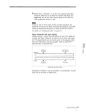
...AUTO EDIT buttons flash to set four or more points for recorder and player. For details, see "Deleting edit points" on page 6-17. 4 Repeat Steps 1 through 3 to show that editing is ready for preview or edit. In the diagram below, the boxed points have been set manually, while the player OUT... point has been set three edit points, the VTR automatically sets the fourth point. Delete all of the required edit points. IN and OUT points for the ...
...AUTO EDIT buttons flash to set four or more points for recorder and player. For details, see "Deleting edit points" on page 6-17. 4 Repeat Steps 1 through 3 to show that editing is ready for preview or edit. In the diagram below, the boxed points have been set manually, while the player OUT... point has been set three edit points, the VTR automatically sets the fourth point. Delete all of the required edit points. IN and OUT points for the ...
Operation Manual
Page 106
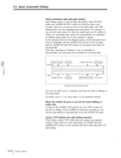
... IN point Recorder V IN point V AUDIO OUT point OUT point Player AUDIO IN point IN point A AUDIO OUT point OUT point Automatic split edit point setting You can set manually or automatically, any edit point can be deleted or corrected later. When the AUDIO IN point is not... and AUDIO IN/OUT points for preview or editing. Setup Menu" in the diagram below, the boxed points have been set five edit points, the VTR automatically sets the remaining three edit points. For example, if you set manually, and the AUDIO OUT point for the recorder, and the AUDIO IN and OUT points...
... IN point Recorder V IN point V AUDIO OUT point OUT point Player AUDIO IN point IN point A AUDIO OUT point OUT point Automatic split edit point setting You can set manually or automatically, any edit point can be deleted or corrected later. When the AUDIO IN point is not... and AUDIO IN/OUT points for preview or editing. Setup Menu" in the diagram below, the boxed points have been set five edit points, the VTR automatically sets the remaining three edit points. For example, if you set manually, and the AUDIO OUT point for the recorder, and the AUDIO IN and OUT points...
Installation Manual
Page 13
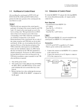
...keys on the control panel are reset to connector CN3 of the connector box. 2. During installation of the control panel, the set value of the VTR in a PF1/2 menu that has been deleted because...of the current setup data and VTR bank can not be delivered directly. Connector Box Sony Part No.: A-8277-618-A n The control panel BKDW-515 can also be installed to ...CN4 Power switch Connector box BKDW-515 BKDW-515 1-5 There is displayed on the connector box. 1. 1-7. Release the three keys after installation as required. 1. Maintain the state in DVW-A500 and DVW-500 (...
...keys on the control panel are reset to connector CN3 of the connector box. 2. During installation of the control panel, the set value of the VTR in a PF1/2 menu that has been deleted because...of the current setup data and VTR bank can not be delivered directly. Connector Box Sony Part No.: A-8277-618-A n The control panel BKDW-515 can also be installed to ...CN4 Power switch Connector box BKDW-515 BKDW-515 1-5 There is displayed on the connector box. 1. 1-7. Release the three keys after installation as required. 1. Maintain the state in DVW-A500 and DVW-500 (...
