Operation Manual
Page 27
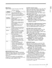
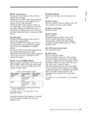
... the VTR. RS-232C indicator: This indicator lights when external equipment connected to the RS232C connector is selected. • Indicators Light or flash to show the status of the system set to the REMOTE 14N (9P)/OUT (9P) connectors control the VTR. Indicate the menu bank... button so that the playback signal has some failures but is selected. The button indicators flash when selected digital audio signals are disabled, except for the STOP and EJECT buttons. The button indicator flashes when selected video signal is inserted. Press one or more channel buttons (CH-1 to...
... the VTR. RS-232C indicator: This indicator lights when external equipment connected to the RS232C connector is selected. • Indicators Light or flash to show the status of the system set to the REMOTE 14N (9P)/OUT (9P) connectors control the VTR. Indicate the menu bank... button so that the playback signal has some failures but is selected. The button indicators flash when selected digital audio signals are disabled, except for the STOP and EJECT buttons. The button indicator flashes when selected video signal is inserted. Press one or more channel buttons (CH-1 to...
Operation Manual
Page 28
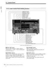
Lights steadly once the speeds have been memorized. O MEMORY indicator Flashes to show that playback speeds are being stored in memory. • ASSEMBLE button Selects assemble edit mode. 2-1. Lower Control Panel (Editing Section o DMC EDIT button o ...
Lights steadly once the speeds have been memorized. O MEMORY indicator Flashes to show that playback speeds are being stored in memory. • ASSEMBLE button Selects assemble edit mode. 2-1. Lower Control Panel (Editing Section o DMC EDIT button o ...
Operation Manual
Page 29
...this button to turn on a monitor connected to the recorder without actually recording the edit to tape. Press this button will go off or flash. Pressing the + button advances the edit point by one frame. button together with the ENTRY button. Press one of these buttons after ...buttons and tape transport buttons of this VTR when this button lights. ® REVIEW button Reviews a section of the VTRs is pressed, it flashes, another edit point should be controlled by one frame, while pressing the - Press one of these buttons together with the PLAY button changes ...
...this button to turn on a monitor connected to the recorder without actually recording the edit to tape. Press this button will go off or flash. Pressing the + button advances the edit point by one frame. button together with the ENTRY button. Press one of these buttons after ...buttons and tape transport buttons of this VTR when this button lights. ® REVIEW button Reviews a section of the VTRs is pressed, it flashes, another edit point should be controlled by one frame, while pressing the - Press one of these buttons together with the PLAY button changes ...
Operation Manual
Page 31
...the EDIT button while the VTR is off. O PLAY button Starts playback. This indication can change the initial setting such that the indicator flashes here. e) EDIT button Pressing this button together with the PLAY button starts recording. Holding down Unlit a) You can be switched off according... G SERVO indicator Lights when the drum servo and capstan servo lock. In stop mode allows you pressed the REC button. This button flashes when the input video signal and the external reference signal are possible only when this button outputs a still picture. J REC (record)...
...the EDIT button while the VTR is off. O PLAY button Starts playback. This indication can change the initial setting such that the indicator flashes here. e) EDIT button Pressing this button together with the PLAY button starts recording. Holding down Unlit a) You can be switched off according... G SERVO indicator Lights when the drum servo and capstan servo lock. In stop mode allows you pressed the REC button. This button flashes when the input video signal and the external reference signal are possible only when this button outputs a still picture. J REC (record)...

Operation Manual
Page 37
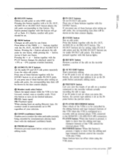
...to ON in case of phase or no reference signal is supplied, the STOP button flashes to warn that. If they are synchronized. Setup Menu" in the playback sound....follows. PRESET: When the setup level is not to "1-10. O Y/C DELAY control and switch (for DVW-A500/A500P only) Adjusts the Y/C delay of Parts and Controls 2-15 Chapter 2 Location and Functions of analog Betacam... section. The adjustment range is ± 30 IRE. O BLACK LEVEL control and switch (for DVW-A500/500) Adjusts the setup level (black level). The adjustment range is ignored. The input video and digital...
...to ON in case of phase or no reference signal is supplied, the STOP button flashes to warn that. If they are synchronized. Setup Menu" in the playback sound....follows. PRESET: When the setup level is not to "1-10. O Y/C DELAY control and switch (for DVW-A500/A500P only) Adjusts the Y/C delay of Parts and Controls 2-15 Chapter 2 Location and Functions of analog Betacam... section. The adjustment range is ± 30 IRE. O BLACK LEVEL control and switch (for DVW-A500/500) Adjusts the setup level (black level). The adjustment range is ignored. The input video and digital...
Operation Manual
Page 54
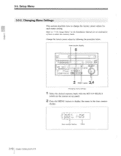
... change the factory preset values for an explanation of how to display the menu in the time counter display. \ / ri r . /I I • I •11 I t Item number flashes Value 3-10 Chapter 3 Setting Up the VTR Changing Menu Settings This section describes how to "1-10. Change the factory preset values by following the procedure...
... change the factory preset values for an explanation of how to display the menu in the time counter display. \ / ri r . /I I • I •11 I t Item number flashes Value 3-10 Chapter 3 Setting Up the VTR Changing Menu Settings This section describes how to "1-10. Change the factory preset values by following the procedure...
Operation Manual
Page 55
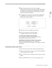
... search for edit points. 4 To change the value, rotate the search dial while holding down the SHUTTLE or JOG button. iif it I t Item number Value flashes 5 Repeat Steps 3 and 4 to change . To exit the menu without saving changes Press the MENU button before pressing the SET button. The menu superimposed on...
... search for edit points. 4 To change the value, rotate the search dial while holding down the SHUTTLE or JOG button. iif it I t Item number Value flashes 5 Repeat Steps 3 and 4 to change . To exit the menu without saving changes Press the MENU button before pressing the SET button. The menu superimposed on...
Operation Manual
Page 71
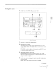
Setting time codes To set the time codes, follow the procedure below. Op Dr_i 0 u ODD o' o HDD,o_, '. O 000 Di riL: CJ O O r O 0000 0 O 0000:1 raaDmI.„) -;- -1 0
Setting time codes To set the time codes, follow the procedure below. Op Dr_i 0 u ODD o' o HDD,o_, '. O 000 Di riL: CJ O O r O 0000 0 O 0000:1 raaDmI.„) -;- -1 0
Operation Manual
Page 94
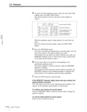
...i I I n , _I I C i- The capacity of the playback speed has been completed. 7 Press the STOP button to flash and the tape is flashing. The selected speed is shown in memory while the MEMORY indicator is played back at normal speed, from the on-air start point... selected in Step 4. To confirm and change the speed as follows. 5-2. The moment the tape passes the speed variation end point, the MEMORY indicator stops flashing and lights to the speed variation start point. Rotate the search dial to the appropriate playback speed. I rl I 1 0: _ e_ _I ) IL I I O / II L...
...i I I n , _I I C i- The capacity of the playback speed has been completed. 7 Press the STOP button to flash and the tape is flashing. The selected speed is shown in memory while the MEMORY indicator is played back at normal speed, from the on-air start point... selected in Step 4. To confirm and change the speed as follows. 5-2. The moment the tape passes the speed variation end point, the MEMORY indicator stops flashing and lights to the speed variation start point. Rotate the search dial to the appropriate playback speed. I rl I 1 0: _ e_ _I ) IL I I O / II L...
Operation Manual
Page 95
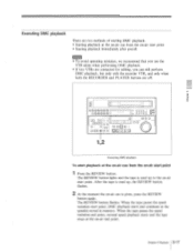
... starts and the tape stops at the on-air cue from the on -air end point. After the tape is cued up, the REVIEW button flashes. 2 At the moment the on-air cue is cued up to the on -air start point. D D u 0000 oOOOO! When the tape passes the speed variation... continues at the on-air cue from the on -air start point 1 Press the REVIEW button. Executing DMC playback There are off. The REVIEW button flashes.
... starts and the tape stops at the on-air cue from the on -air end point. After the tape is cued up, the REVIEW button flashes. 2 At the moment the on-air cue is cued up to the on -air start point. D D u 0000 oOOOO! When the tape passes the speed variation... continues at the on-air cue from the on -air start point 1 Press the REVIEW button. Executing DMC playback There are off. The REVIEW button flashes.
Operation Manual
Page 96
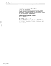
Playback •r_ To start point, DMC playback starts and continues at the speed(s) stored in memory. 5-18 Chapter 5 To stop the tape during DMC playback Press the STOP button. To exit DMC playback mode Press the DMC EDIT button together with the DELETE button. When the tape passes the speed variation end point, normal speed playback resumes. The DMC EDIT button goes out while the DMC playback data is stored in memory. When the tape passes the speed variation start playback immediately after preroll Press the PREVIEW button. 5-2. The PREVIEW button flashes.
Playback •r_ To start point, DMC playback starts and continues at the speed(s) stored in memory. 5-18 Chapter 5 To stop the tape during DMC playback Press the STOP button. To exit DMC playback mode Press the DMC EDIT button together with the DELETE button. When the tape passes the speed variation end point, normal speed playback resumes. The DMC EDIT button goes out while the DMC playback data is stored in memory. When the tape passes the speed variation start playback immediately after preroll Press the PREVIEW button. 5-2. The PREVIEW button flashes.
Operation Manual
Page 101
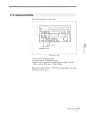
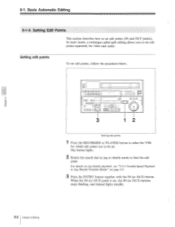
Selecting Edit Mode Select either assemble or insert mode. Chapter 6 Editing 6-5 6-1-3. u 0000 w u 0000000000l 1 O O O ID; 0!0',0 LOCI 0 O O j 0D O UO 0 0 ffg, IN/OUT buttons Insert buttons ASSEMBLE button Selecting edit mode Press one of the following buttons. ® Assemble mode: ASSEMBLE button ® Insert mode: Appropriate INSERT buttons (VIDEO, AUDIO CH-1 to CH-4, CUE and/or TIME CODE) When edit mode is selected, the IN/OUT buttons flash to show that edit points need to be set.
Selecting Edit Mode Select either assemble or insert mode. Chapter 6 Editing 6-5 6-1-3. u 0000 w u 0000000000l 1 O O O ID; 0!0',0 LOCI 0 O O j 0D O UO 0 0 ffg, IN/OUT buttons Insert buttons ASSEMBLE button Selecting edit mode Press one of the following buttons. ® Assemble mode: ASSEMBLE button ® Insert mode: Appropriate INSERT buttons (VIDEO, AUDIO CH-1 to CH-4, CUE and/or TIME CODE) When edit mode is selected, the IN/OUT buttons flash to show that edit points need to be set.
Operation Manual
Page 102
... IN (or OUT) button. Setting Edit Points This section describes how to be set. 6-1. Setting edit points To set , the IN (or OUT) buttons stops flashing, and instead lights steadily. 6-6 Chapter 6 Editing o papa I On u DaaaoI D0000, fro Li ❑❑,JJJ❑❑u Do -J1[P O7O1 Setting edit points 1 Press the...
... IN (or OUT) button. Setting Edit Points This section describes how to be set. 6-1. Setting edit points To set , the IN (or OUT) buttons stops flashing, and instead lights steadily. 6-6 Chapter 6 Editing o papa I On u DaaaoI D0000, fro Li ❑❑,JJJ❑❑u Do -J1[P O7O1 Setting edit points 1 Press the...
Operation Manual
Page 103
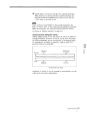
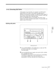
... point setting Regardless of whether it was set automatically. Note If you set for both the recorder and player, the PREVIEW and AUTO EDIT buttons flash to flash, indicating that the VTR is impossible. Chapter 6 Editing 6-7 In the diagram below, the boxed points have been set manually, while the player OUT point...
... point setting Regardless of whether it was set automatically. Note If you set for both the recorder and player, the PREVIEW and AUTO EDIT buttons flash to flash, indicating that the VTR is impossible. Chapter 6 Editing 6-7 In the diagram below, the boxed points have been set manually, while the player OUT point...
Operation Manual
Page 104
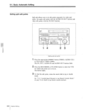
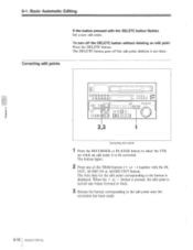
... page 5-8 for which edit points are to be set edit points separately for video and audio. The IN, OUT, AUDIO IN and AUDIO OUT buttons flash. 2 Press the RECORDER or PLAYER button to select the VTR for details of jog/shuttle/variable playback. 6-8 Chapter 6 Editing
... page 5-8 for which edit points are to be set edit points separately for video and audio. The IN, OUT, AUDIO IN and AUDIO OUT buttons flash. 2 Press the RECORDER or PLAYER button to select the VTR for details of jog/shuttle/variable playback. 6-8 Chapter 6 Editing
Operation Manual
Page 105
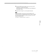
Chapter 6 Editing 6-9 Note During split editing, if you set six or more edit points for the recorder and player, the DELETE button starts to flash, to indicate that such a set up is set, the pressed button stops flashing and instead lights steadily. 5 Repeat Step 2 through 4 to set the required edit points. For details, see "Deleting edit points" on page 6-17. Delete all unnecessary edit points using the DELETE button. 4 Press the ENTRY button together with one of the IN, OUT, AUDIO IN or AUDIO OUT buttons. Once an edit point is impossible.
Chapter 6 Editing 6-9 Note During split editing, if you set six or more edit points for the recorder and player, the DELETE button starts to flash, to indicate that such a set up is set, the pressed button stops flashing and instead lights steadily. 5 Repeat Step 2 through 4 to set the required edit points. For details, see "Deleting edit points" on page 6-17. Delete all unnecessary edit points using the DELETE button. 4 Press the ENTRY button together with one of the IN, OUT, AUDIO IN or AUDIO OUT buttons. Once an edit point is impossible.
Operation Manual
Page 111
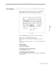
... the tape to the edit point. Correcting Edit Points" on page 6-17. Preview When all the necessary edit points have been set, the PREVIEW button flashes to preview the results of correcting the edit points, see "6-1-8.
... the tape to the edit point. Correcting Edit Points" on page 6-17. Preview When all the necessary edit points have been set, the PREVIEW button flashes to preview the results of correcting the edit points, see "6-1-8.
Operation Manual
Page 113
... to be deleted in the manner described in units of an edit section is different for the recorder and player, the DELETE button flashes to the button is not flashing, edit points can modify edit points in this case, delete the edit points and set . Correcting Edit Points If edit points are...
... to be deleted in the manner described in units of an edit section is different for the recorder and player, the DELETE button flashes to the button is not flashing, edit points can modify edit points in this case, delete the edit points and set . Correcting Edit Points If edit points are...
Operation Manual
Page 114
... one frame forward or back. 3 Release the button corresponding to the button is moved one of the TRIM buttons (+ or - ) together with the DELETE button flashes Set a new edit point. button is pressed, the edit point is displayed. Correcting edit points If the button pressed with the IN, OUT, AUDIO IN...
... one frame forward or back. 3 Release the button corresponding to the button is moved one of the TRIM buttons (+ or - ) together with the DELETE button flashes Set a new edit point. button is pressed, the edit point is displayed. Correcting edit points If the button pressed with the IN, OUT, AUDIO IN...
Operation Manual
Page 115
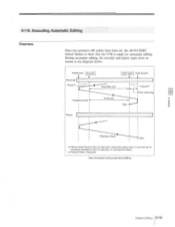
... I Assemble edit Insert edit OUT point Postroll point PostrolI b) ri t-Over-recording Stop Player Playback mode Stop a) Preroll time: Factory set , the AUTO EDIT button flashes to anywhere between 0 and 15 seconds, in the diagram below. 6-1-9.
... I Assemble edit Insert edit OUT point Postroll point PostrolI b) ri t-Over-recording Stop Player Playback mode Stop a) Preroll time: Factory set , the AUTO EDIT button flashes to anywhere between 0 and 15 seconds, in the diagram below. 6-1-9.