
Operating Instructions
Page 1
Printed on recycled paper. Sony Corporation 4-149-933-11 (1) HD Color Video Camera Printed in Japan Operating Instructions Before operating the unit, please read this manual thoroughly and retain it for future reference. BRC-Z330 © 2009 Sony Corporation
Printed on recycled paper. Sony Corporation 4-149-933-11 (1) HD Color Video Camera Printed in Japan Operating Instructions Before operating the unit, please read this manual thoroughly and retain it for future reference. BRC-Z330 © 2009 Sony Corporation
Operating Instructions
Page 2
... power plug to provide reasonable protection against harmful interference when the equipment is operated in this manual could void your nearest authorized Sony service facility. Refer servicing to correct the interference at his own expense. Disconnect device of this equipment is installed near the... a Class A product. WARNING To reduce the risk of fire or electric shock, do not open the cabinet. Operation of FCC Rules. BRC-Z330 Serial No. This product has no power switch. For the customers in the residential area. 2 The Authorized Representative for a digital device pursuant...
... power plug to provide reasonable protection against harmful interference when the equipment is operated in this manual could void your nearest authorized Sony service facility. Refer servicing to correct the interference at his own expense. Disconnect device of this equipment is installed near the... a Class A product. WARNING To reduce the risk of fire or electric shock, do not open the cabinet. Operation of FCC Rules. BRC-Z330 Serial No. This product has no power switch. For the customers in the residential area. 2 The Authorized Representative for a digital device pursuant...
Operating Instructions
Page 3
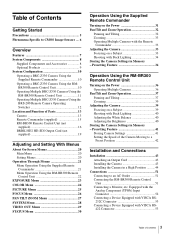
...Connecting a Monitor, etc. Table of Contents BR300 Remote Control Unit 10 Operating Multiple BRC-Z330 Cameras Using the RM-BR300 Remote Control Unit 11 Operating Multiple BRC-Z330 Cameras Using the BRS-200 Remote Camera Operating Switcher 12 Location and Function of ... Features 7 System Components 8 Supplied Components and Accessories 8 Optional Products 9 System Configuration 10 Operating a BRC-Z330 Camera Using the Supplied Remote Commander 10 Operating a BRC-Z330 Camera Using the RM- Presetting Feature 34 Operation Using the RM-BR300 Remote Control Unit Turning on the...
...Connecting a Monitor, etc. Table of Contents BR300 Remote Control Unit 10 Operating Multiple BRC-Z330 Cameras Using the RM-BR300 Remote Control Unit 11 Operating Multiple BRC-Z330 Cameras Using the BRS-200 Remote Camera Operating Switcher 12 Location and Function of ... Features 7 System Components 8 Supplied Components and Accessories 8 Optional Products 9 System Configuration 10 Operating a BRC-Z330 Camera Using the Supplied Remote Commander 10 Operating a BRC-Z330 Camera Using the RM- Presetting Feature 34 Operation Using the RM-BR300 Remote Control Unit Turning on the...
Operating Instructions
Page 10
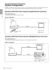
... : To perform pan/tilt and zoom operations using optional products. BRC-Z330 RM-BR300 Remote Control Unit Video signal Remote Control (VISCA) signal , Signal flow 10 System Configuration System Configuration The BRC-Z330 HD Color Video Camera has various system configuration capabilities using the joystick...Unit System configuration HD video monitor, VTR, etc. Overview Remote Commander (supplied) Video signal Signal flow Operating a BRC-Z330 Camera Using the RM-BR300 Remote Control Unit This system allows you : To operate the camera readily from a short distance System ...
... : To perform pan/tilt and zoom operations using optional products. BRC-Z330 RM-BR300 Remote Control Unit Video signal Remote Control (VISCA) signal , Signal flow 10 System Configuration System Configuration The BRC-Z330 HD Color Video Camera has various system configuration capabilities using the joystick...Unit System configuration HD video monitor, VTR, etc. Overview Remote Commander (supplied) Video signal Signal flow Operating a BRC-Z330 Camera Using the RM-BR300 Remote Control Unit This system allows you : To operate the camera readily from a short distance System ...
Operating Instructions
Page 11
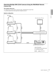
BRC-Z330 BRC-Z330 Video switcher RM-BR300 Remote Control Unit Video signal Remote control (VISCA) signal Tally/contact signal , Signal flow 11 System Configuration Overview Operating Multiple BRC-Z330 Cameras Using the RM-BR300 Remote Control Unit This system allows you: • To operate up to seven cameras remotely using a single Remote Control Unit • To perform pan/tilt and zoom operations using the joystick System configuration BRC-Z330 HD video monitor, VTR, etc.
BRC-Z330 BRC-Z330 Video switcher RM-BR300 Remote Control Unit Video signal Remote control (VISCA) signal Tally/contact signal , Signal flow 11 System Configuration Overview Operating Multiple BRC-Z330 Cameras Using the RM-BR300 Remote Control Unit This system allows you: • To operate up to seven cameras remotely using a single Remote Control Unit • To perform pan/tilt and zoom operations using the joystick System configuration BRC-Z330 HD video monitor, VTR, etc.
Operating Instructions
Page 12
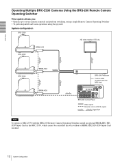
...Panel Video signal Remote control (VISCA) signal , Signal flow Note To operate a BRC-Z330 with the BRS-200 Remote Camera Operating Switcher, install an optional BRBK-HD2 HDSDI Output Card in the BRC-Z330, which cannot be controlled this way without a BRBK-HD2 HD-SDI Output Card ...installed. 12 System Configuration Overview Operating Multiple BRC-Z330 Cameras Using the BRS-200 Remote Camera Operating Switcher This system allows ...
...Panel Video signal Remote control (VISCA) signal , Signal flow Note To operate a BRC-Z330 with the BRS-200 Remote Camera Operating Switcher, install an optional BRBK-HD2 HDSDI Output Card in the BRC-Z330, which cannot be controlled this way without a BRBK-HD2 HD-SDI Output Card ...installed. 12 System Configuration Overview Operating Multiple BRC-Z330 Cameras Using the BRS-200 Remote Camera Operating Switcher This system allows ...
Operating Instructions
Page 16
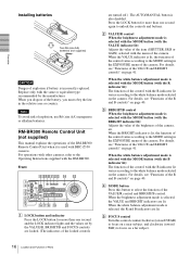
.... For details, see "Functions of the control with the RM-BR300. C BRIGHT/B control When the brightness adjustment mode is selected with the MODE button (with BRC-Z330 cameras. When you must obey the law in the EXPOSURE menu of Parts Press the LOCK button for more than one second again to select...
.... For details, see "Functions of the control with the RM-BR300. C BRIGHT/B control When the brightness adjustment mode is selected with the MODE button (with BRC-Z330 cameras. When you must obey the law in the EXPOSURE menu of Parts Press the LOCK button for more than one second again to select...
Operating Instructions
Page 18
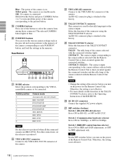
... 7 to each POSITION button, and load the settings in blue. Switch position 0 1 2 3 4 5 6 7 8 Camera mode Automatically selected (default) BRC-300/300P EVI-D70/D70P EVI-D100/D100P EVI-D30/D30P SNC-RZ30N BRC-H700 BRC-Z700 BRC-Z330 Note Set the selector to ON for 38400bps, or OFF for the tally lamp input or the contact... memory. X TALLY/CONTACT connector This connector is attached at the factory. Switch 2 (Communication baud rate selector) Set to position 8 when all the connected cameras are BRC-Z330s.
... 7 to each POSITION button, and load the settings in blue. Switch position 0 1 2 3 4 5 6 7 8 Camera mode Automatically selected (default) BRC-300/300P EVI-D70/D70P EVI-D100/D100P EVI-D30/D30P SNC-RZ30N BRC-H700 BRC-Z700 BRC-Z330 Note Set the selector to ON for 38400bps, or OFF for the tally lamp input or the contact... memory. X TALLY/CONTACT connector This connector is attached at the factory. Switch 2 (Communication baud rate selector) Set to position 8 when all the connected cameras are BRC-Z330s.
Operating Instructions
Page 30
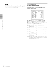
... settings selected with the menus. PAGE2: Shows the settings selected with the VIDEO OUT menu, status of the fan motors, the firmware versions of the BRC-Z330. 30 STATUS Menu EXPOSURE AE SPEED AGC LIMIT IRIS LIMIT EX-COMP BACK LIGHT SPOT LIGHT COLOR AE ND FILTER PAGE1 FULL AUTO MID 12dB...
... settings selected with the menus. PAGE2: Shows the settings selected with the VIDEO OUT menu, status of the fan motors, the firmware versions of the BRC-Z330. 30 STATUS Menu EXPOSURE AE SPEED AGC LIMIT IRIS LIMIT EX-COMP BACK LIGHT SPOT LIGHT COLOR AE ND FILTER PAGE1 FULL AUTO MID 12dB...
Operating Instructions
Page 53
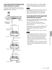
...232C Connector Connections with the VISCA RS-232C cables (cross type) enable control of multiple cameras. This allows the connection up to Seventh BRC-Z330 Installation and Connections 53 Connections Connecting a Device Equipped with VISCA RS-422 Connector Connection via the VISCA RS-422 connectors enables control of ... of the camera (page 14) and the DIP switch on the bottom of the RS-422 connector plugs, see page 73. DC IN 12V Second BRC-Z330 VISCA RS-232C OUT RS-232C cable VISCA RS-232C IN ! 1 2 3 4 5 6 7 8 9 IR SELECT R 1 OFF ON 2 3 DATA MIX VISCA RS-422 OFF...
...232C Connector Connections with the VISCA RS-232C cables (cross type) enable control of multiple cameras. This allows the connection up to Seventh BRC-Z330 Installation and Connections 53 Connections Connecting a Device Equipped with VISCA RS-422 Connector Connection via the VISCA RS-422 connectors enables control of ... of the camera (page 14) and the DIP switch on the bottom of the RS-422 connector plugs, see page 73. DC IN 12V Second BRC-Z330 VISCA RS-232C OUT RS-232C cable VISCA RS-232C IN ! 1 2 3 4 5 6 7 8 9 IR SELECT R 1 OFF ON 2 3 DATA MIX VISCA RS-422 OFF...

Operating Instructions
Page 54
... VIDEO RGB/COMPONENT First BRCZ330 DC IN 12V VISCA RS-422 VISCA RS-422 cable VISCA RS-422 ! 1 2 3 4 5 6 7 8 9 IR SELECT R 1 OFF ON 2 3 DATA MIX VISCA RS-422 OFF 75 ON EXT SYNC IN DC IN 12V IN VISCA RS-232C OUT S VIDEO VIDEO RGB/COMPONENT Second BRC-Z330 DC IN 12V VISCA RS...-422 OFF ON 75 EXT SYNC IN DC IN 12V IN VISCA RS-232C OUT S VIDEO VIDEO RGB/COMPONENT DC IN 12V Third to Seventh BRC-Z330 ! 1 2 3 4 5 6 7 8 9 IR SELECT R 1 OFF ON 2 3 DATA MIX VISCA RS-422 OFF ON 75 EXT SYNC IN DC IN 12V IN VISCA RS-232C OUT S VIDEO VIDEO...
... VIDEO RGB/COMPONENT First BRCZ330 DC IN 12V VISCA RS-422 VISCA RS-422 cable VISCA RS-422 ! 1 2 3 4 5 6 7 8 9 IR SELECT R 1 OFF ON 2 3 DATA MIX VISCA RS-422 OFF 75 ON EXT SYNC IN DC IN 12V IN VISCA RS-232C OUT S VIDEO VIDEO RGB/COMPONENT Second BRC-Z330 DC IN 12V VISCA RS...-422 OFF ON 75 EXT SYNC IN DC IN 12V IN VISCA RS-232C OUT S VIDEO VIDEO RGB/COMPONENT DC IN 12V Third to Seventh BRC-Z330 ! 1 2 3 4 5 6 7 8 9 IR SELECT R 1 OFF ON 2 3 DATA MIX VISCA RS-422 OFF ON 75 EXT SYNC IN DC IN 12V IN VISCA RS-232C OUT S VIDEO VIDEO...

Operating Instructions
Page 56
... 12V IN VISCA RS-232C OUT S VIDEO VIDEO RGB/COMPONENT DC IN 12V VIDEO Video monitor, etc. Third to seven cameras. Third to Seventh (last) BRC-Z330 75-ohm termination switch: ON ! 1 2 3 4 5 6 7 8 9 IR SELECT R 1 OFF ON 2 3 DATA MIX VISCA RS-422 OFF ON 75... generator Commercially available T-type signal separator Commercially available T-type signal separator Installation and Connections 56 Connections EXT SYNC IN 75-ohm termination switch: OFF Second BRCZ330 to video input ! 1 2 3 4 5 6 7 8 9 IR SELECT R 1 OFF ON 2 3 DATA MIX VISCA RS-422 OFF ON 75 EXT SYNC...
... 12V IN VISCA RS-232C OUT S VIDEO VIDEO RGB/COMPONENT DC IN 12V VIDEO Video monitor, etc. Third to seven cameras. Third to Seventh (last) BRC-Z330 75-ohm termination switch: ON ! 1 2 3 4 5 6 7 8 9 IR SELECT R 1 OFF ON 2 3 DATA MIX VISCA RS-422 OFF ON 75... generator Commercially available T-type signal separator Commercially available T-type signal separator Installation and Connections 56 Connections EXT SYNC IN 75-ohm termination switch: OFF Second BRCZ330 to video input ! 1 2 3 4 5 6 7 8 9 IR SELECT R 1 OFF ON 2 3 DATA MIX VISCA RS-422 OFF ON 75 EXT SYNC...
Operating Instructions
Page 57
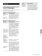
... setting becomes effective. Messages for a while. Turn off the power of the camera, and consult with your Sony dealer. Indicators on the screen. Wait for the BRC-Z330 camera Message Meaning/remedies Please restart system You are prompted to restart the power of the camera after moving due...the numbers 01 to 16) message will fail to turn it will appear. Appendix List of Messages The following messages may appear on the BRC-Z330 camera Indicator STANDBY lamp flashes. To start the H PHASE adjustment, press the HOME button on the Remote Commander or the button on ...
... setting becomes effective. Messages for a while. Turn off the power of the camera, and consult with your Sony dealer. Indicators on the screen. Wait for the BRC-Z330 camera Message Meaning/remedies Please restart system You are prompted to restart the power of the camera after moving due...the numbers 01 to 16) message will fail to turn it will appear. Appendix List of Messages The following messages may appear on the BRC-Z330 camera Indicator STANDBY lamp flashes. To start the H PHASE adjustment, press the HOME button on the Remote Commander or the button on ...
Operating Instructions
Page 70
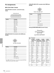
... Analog RGB/COMPONENT (D-sub 15-pin) RGB/COMPONENT Pin Function No. RXD IN+ TXD IN - Tri-level Bi-level SYNC-OUT OUT SYNC- Pin Assignments BRC-Z330 Video Camera VISCA RS-422 connector (connector plug 9-pin) VISCA RS-422 123456789 Pin No. 1 2 3 4 5 6 7 8 9 Function RXD OUT - TXD IN+ VISCA RS-232C IN connector...
... Analog RGB/COMPONENT (D-sub 15-pin) RGB/COMPONENT Pin Function No. RXD IN+ TXD IN - Tri-level Bi-level SYNC-OUT OUT SYNC- Pin Assignments BRC-Z330 Video Camera VISCA RS-422 connector (connector plug 9-pin) VISCA RS-422 123456789 Pin No. 1 2 3 4 5 6 7 8 9 Function RXD OUT - TXD IN+ VISCA RS-232C IN connector...
Operating Instructions
Page 72
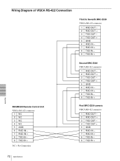
Wiring Diagram of VISCA RS-422 Connection Third to Seventh BRC-Z330 VISCA RS-422 connector 1 RXD OUT - 2 RXD OUT + 3 TXD OUT - 4 TXD OUT + 5 GND 6 RXD IN - 7 RXD IN + 8 TXD IN - 9 TXD IN + RM-BR300 Remote Control ...Unit VISCA RS-422 connector 1 NC 2 NC 3 NC 4 NC 5 GND 6 RXD IN - 7 RXD IN + 8 TXD IN - 9 TXD IN + NC = No Connection Second BRC-Z330 VISCA RS-422 connector 1 RXD OUT - 2 RXD OUT + 3 TXD OUT - 4 TXD OUT + 5 GND 6 RXD IN - 7 RXD IN + 8 TXD IN - 9 TXD IN + First...
Wiring Diagram of VISCA RS-422 Connection Third to Seventh BRC-Z330 VISCA RS-422 connector 1 RXD OUT - 2 RXD OUT + 3 TXD OUT - 4 TXD OUT + 5 GND 6 RXD IN - 7 RXD IN + 8 TXD IN - 9 TXD IN + RM-BR300 Remote Control ...Unit VISCA RS-422 connector 1 NC 2 NC 3 NC 4 NC 5 GND 6 RXD IN - 7 RXD IN + 8 TXD IN - 9 TXD IN + NC = No Connection Second BRC-Z330 VISCA RS-422 connector 1 RXD OUT - 2 RXD OUT + 3 TXD OUT - 4 TXD OUT + 5 GND 6 RXD IN - 7 RXD IN + 8 TXD IN - 9 TXD IN + First...