
Operating Instructions
Page 1
Sony Corporation 4-149-933-11 (1) HD Color Video Camera Printed in Japan Operating Instructions Before operating the unit, please read this manual thoroughly and retain it for future reference. BRC-Z330 © 2009 Sony Corporation Printed on recycled paper.
Sony Corporation 4-149-933-11 (1) HD Color Video Camera Printed in Japan Operating Instructions Before operating the unit, please read this manual thoroughly and retain it for future reference. BRC-Z330 © 2009 Sony Corporation Printed on recycled paper.
Operating Instructions
Page 2
... expressly approved in hazards such as a power supply source. BRC-Z330 Serial No. Any other power sources may not cause harmful interference, and (2) this device may result in this manual could void your Sony dealer regarding this equipment must be required to the following two... for EMC and product safety is subject to correct the interference at his own expense. Operation of this equipment. Operation is Sony Deutschland GmbH, Hedelfinger Strasse 61, 70327 Stuttgart, Germany. The Authorized Representative for installing the equipment on the bottom. Record these...
... expressly approved in hazards such as a power supply source. BRC-Z330 Serial No. Any other power sources may not cause harmful interference, and (2) this device may result in this manual could void your Sony dealer regarding this equipment must be required to the following two... for EMC and product safety is subject to correct the interference at his own expense. Operation of this equipment. Operation is Sony Deutschland GmbH, Hedelfinger Strasse 61, 70327 Stuttgart, Germany. The Authorized Representative for installing the equipment on the bottom. Record these...
Operating Instructions
Page 3
...Overview Features 7 System Components 8 Supplied Components and Accessories 8 Optional Products 9 System Configuration 10 Operating a BRC-Z330 Camera Using the Supplied Remote Commander 10 Operating a BRC-Z330 Camera Using the RM- Presetting Feature 34 Operation Using the RM-BR300 Remote Control Unit Turning on the ...40 Storing the Camera Settings in Memory - BR300 Remote Control Unit 10 Operating Multiple BRC-Z330 Cameras Using the RM-BR300 Remote Control Unit 11 Operating Multiple BRC-Z330 Cameras Using the BRS-200 Remote Camera Operating Switcher 12 Location and Function of ...
...Overview Features 7 System Components 8 Supplied Components and Accessories 8 Optional Products 9 System Configuration 10 Operating a BRC-Z330 Camera Using the Supplied Remote Commander 10 Operating a BRC-Z330 Camera Using the RM- Presetting Feature 34 Operation Using the RM-BR300 Remote Control Unit Turning on the ...40 Storing the Camera Settings in Memory - BR300 Remote Control Unit 10 Operating Multiple BRC-Z330 Cameras Using the RM-BR300 Remote Control Unit 11 Operating Multiple BRC-Z330 Cameras Using the BRS-200 Remote Camera Operating Switcher 12 Location and Function of ...
Operating Instructions
Page 10
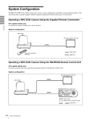
...Using the Supplied Remote Commander This system allows you : To perform pan/tilt and zoom operations using optional products. BRC-Z330 RM-BR300 Remote Control Unit Video signal Remote Control (VISCA) signal , Signal flow 10 System Configuration This section describes...required components and the main usage of the Remote Control Unit System configuration HD video monitor, VTR, etc. System Configuration The BRC-Z330 HD Color Video Camera has various system configuration capabilities using the joystick of each system. Overview Remote Commander (supplied) Video signal ...
...Using the Supplied Remote Commander This system allows you : To perform pan/tilt and zoom operations using optional products. BRC-Z330 RM-BR300 Remote Control Unit Video signal Remote Control (VISCA) signal , Signal flow 10 System Configuration This section describes...required components and the main usage of the Remote Control Unit System configuration HD video monitor, VTR, etc. System Configuration The BRC-Z330 HD Color Video Camera has various system configuration capabilities using the joystick of each system. Overview Remote Commander (supplied) Video signal ...
Operating Instructions
Page 11
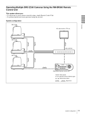
BRC-Z330 BRC-Z330 Video switcher RM-BR300 Remote Control Unit Video signal Remote control (VISCA) signal Tally/contact signal , Signal flow 11 System Configuration Overview Operating Multiple BRC-Z330 Cameras Using the RM-BR300 Remote Control Unit This system allows you: • To operate up to seven cameras remotely using a single Remote Control Unit • To perform pan/tilt and zoom operations using the joystick System configuration BRC-Z330 HD video monitor, VTR, etc.
BRC-Z330 BRC-Z330 Video switcher RM-BR300 Remote Control Unit Video signal Remote control (VISCA) signal Tally/contact signal , Signal flow 11 System Configuration Overview Operating Multiple BRC-Z330 Cameras Using the RM-BR300 Remote Control Unit This system allows you: • To operate up to seven cameras remotely using a single Remote Control Unit • To perform pan/tilt and zoom operations using the joystick System configuration BRC-Z330 HD video monitor, VTR, etc.
Operating Instructions
Page 12
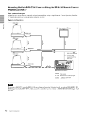
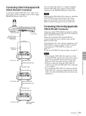
...a single Remote Camera Operating Switcher • To perform pan/tilt and zoom operations using the joystick System configuration BRC-Z330 HD video monitor, VTR, etc. BRBK-HD2 BRC-Z330 BRC-Z330 BRBK-HD2 BRBK-HD2 BRS-200 Processor Control cable (supplied with the BRS-200) BRS-200 REMOTE CAMERA OPERATING ...Panel Video signal Remote control (VISCA) signal , Signal flow Note To operate a BRC-Z330 with the BRS-200 Remote Camera Operating Switcher, install an optional BRBK-HD2 HDSDI Output Card in the BRC-Z330, which cannot be controlled this way without a BRBK-HD2 HD-SDI Output Card installed...
...a single Remote Camera Operating Switcher • To perform pan/tilt and zoom operations using the joystick System configuration BRC-Z330 HD video monitor, VTR, etc. BRBK-HD2 BRC-Z330 BRC-Z330 BRBK-HD2 BRBK-HD2 BRS-200 Processor Control cable (supplied with the BRS-200) BRS-200 REMOTE CAMERA OPERATING ...Panel Video signal Remote control (VISCA) signal , Signal flow Note To operate a BRC-Z330 with the BRS-200 Remote Camera Operating Switcher, install an optional BRBK-HD2 HDSDI Output Card in the BRC-Z330, which cannot be controlled this way without a BRBK-HD2 HD-SDI Output Card installed...
Operating Instructions
Page 16
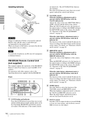
... control with the BRIGHT indicator lit): Adjusts the value of the brightness of Parts E FOCUS control Turn this button to the Operating Instructions supplied with BRC-Z330 cameras. C BRIGHT/B control When the brightness adjustment mode is used with the RM-BR300. When you dispose of explosion, use R6 (size AA) manganese or...
... control with the BRIGHT indicator lit): Adjusts the value of the brightness of Parts E FOCUS control Turn this button to the Operating Instructions supplied with BRC-Z330 cameras. C BRIGHT/B control When the brightness adjustment mode is used with the RM-BR300. When you dispose of explosion, use R6 (size AA) manganese or...
Operating Instructions
Page 18
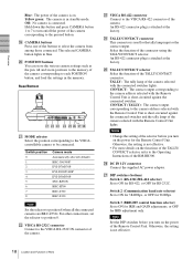
...TALLY/CONTACT ! Switch position 0 1 2 3 4 5 6 7 8 Camera mode Automatically selected (default) BRC-300/300P EVI-D70/D70P EVI-D100/D100P EVI-D30/D30P SNC-RZ30N BRC-H700 BRC-Z700 BRC-Z330 Note Set the selector to position 0. CONTACT (TALLY): The contact output corresponding to the memory of the TALLY...button. The selected CAMERA button lights in blue. For other connections, set the selector to position 8 when all the connected cameras are BRC-Z330s. An RS-422 connector plug is attached at the factory. TALLY: The tally lamp of the camera corresponding to turn on . Notes...
...TALLY/CONTACT ! Switch position 0 1 2 3 4 5 6 7 8 Camera mode Automatically selected (default) BRC-300/300P EVI-D70/D70P EVI-D100/D100P EVI-D30/D30P SNC-RZ30N BRC-H700 BRC-Z700 BRC-Z330 Note Set the selector to position 0. CONTACT (TALLY): The contact output corresponding to the memory of the TALLY...button. The selected CAMERA button lights in blue. For other connections, set the selector to position 8 when all the connected cameras are BRC-Z330s. An RS-422 connector plug is attached at the factory. TALLY: The tally lamp of the camera corresponding to turn on . Notes...
Operating Instructions
Page 30
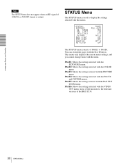
... selected with the COLOR menu. PAGE2: Shows the settings selected with the VIDEO OUT menu, status of the fan motors, the firmware versions of the BRC-Z330. 30 STATUS Menu PAGE5: Shows the settings selected with the B or b button. You can switch the pages with the PAN TILT ZOOM menu. PAGE4: Shows...
... selected with the COLOR menu. PAGE2: Shows the settings selected with the VIDEO OUT menu, status of the fan motors, the firmware versions of the BRC-Z330. 30 STATUS Menu PAGE5: Shows the settings selected with the B or b button. You can switch the pages with the PAN TILT ZOOM menu. PAGE4: Shows...
Operating Instructions
Page 53
DC IN 12V Second BRC-Z330 VISCA RS-232C OUT RS-232C cable VISCA RS-232C IN ! 1 2 3 4 5 6 7 8 9 IR SELECT R 1 OFF ...RGB/COMPONENT DC IN 12V Third to 1,200 m (3,937 feet) away. This allows the connection up to Seventh BRC-Z330 Installation and Connections 53 Connections Prepare the connecting cable using the RS-422 connector plugs that come with the VISCA RS... VISCA RS-422 OFF 75 ON EXT SYNC IN DC IN 12V IN VISCA RS-232C OUT S VIDEO VIDEO RGB/COMPONENT DC IN 12V First BRC-Z330 VISCA RS-232C OUT RS-232C cable VISCA RS-232C IN ! 1 2 3 4 5 6 7 8 9 IR SELECT R 1 OFF ...
DC IN 12V Second BRC-Z330 VISCA RS-232C OUT RS-232C cable VISCA RS-232C IN ! 1 2 3 4 5 6 7 8 9 IR SELECT R 1 OFF ...RGB/COMPONENT DC IN 12V Third to 1,200 m (3,937 feet) away. This allows the connection up to Seventh BRC-Z330 Installation and Connections 53 Connections Prepare the connecting cable using the RS-422 connector plugs that come with the VISCA RS... VISCA RS-422 OFF 75 ON EXT SYNC IN DC IN 12V IN VISCA RS-232C OUT S VIDEO VIDEO RGB/COMPONENT DC IN 12V First BRC-Z330 VISCA RS-232C OUT RS-232C cable VISCA RS-232C IN ! 1 2 3 4 5 6 7 8 9 IR SELECT R 1 OFF ...

Operating Instructions
Page 54
... VIDEO RGB/COMPONENT First BRCZ330 DC IN 12V VISCA RS-422 VISCA RS-422 cable VISCA RS-422 ! 1 2 3 4 5 6 7 8 9 IR SELECT R 1 OFF ON 2 3 DATA MIX VISCA RS-422 OFF 75 ON EXT SYNC IN DC IN 12V IN VISCA RS-232C OUT S VIDEO VIDEO RGB/COMPONENT Second BRC-Z330 DC IN 12V VISCA RS...-422 OFF ON 75 EXT SYNC IN DC IN 12V IN VISCA RS-232C OUT S VIDEO VIDEO RGB/COMPONENT DC IN 12V Third to Seventh BRC-Z330 ! 1 2 3 4 5 6 7 8 9 IR SELECT R 1 OFF ON 2 3 DATA MIX VISCA RS-422 OFF ON 75 EXT SYNC IN DC IN 12V IN VISCA RS-232C OUT S VIDEO VIDEO...
... VIDEO RGB/COMPONENT First BRCZ330 DC IN 12V VISCA RS-422 VISCA RS-422 cable VISCA RS-422 ! 1 2 3 4 5 6 7 8 9 IR SELECT R 1 OFF ON 2 3 DATA MIX VISCA RS-422 OFF 75 ON EXT SYNC IN DC IN 12V IN VISCA RS-232C OUT S VIDEO VIDEO RGB/COMPONENT Second BRC-Z330 DC IN 12V VISCA RS...-422 OFF ON 75 EXT SYNC IN DC IN 12V IN VISCA RS-232C OUT S VIDEO VIDEO RGB/COMPONENT DC IN 12V Third to Seventh BRC-Z330 ! 1 2 3 4 5 6 7 8 9 IR SELECT R 1 OFF ON 2 3 DATA MIX VISCA RS-422 OFF ON 75 EXT SYNC IN DC IN 12V IN VISCA RS-232C OUT S VIDEO VIDEO...

Operating Instructions
Page 56
...ohm termination switch: OFF First BRCZ330 ! 1 2 3 4 5 6 7 8 9 IR SELECT R 1 OFF ON 2 3 DATA MIX VISCA RS-422 OFF 75 ON EXT SYNC IN DC IN 12V IN VISCA RS-232C OUT S VIDEO VIDEO RGB/COMPONENT DC IN 12V EXT SYNC IN 75-ohm coaxial cable to Seventh (last) BRC-Z330 75-ohm termination switch: ON... SYNC IN DC IN 12V IN VISCA RS-232C OUT S VIDEO VIDEO RGB/COMPONENT DC IN 12V VIDEO Video monitor, etc. Third to Seventh (last) BRC-Z330 75-ohm termination switch: ON ! 1 2 3 4 5 6 7 8 9 IR SELECT R 1 OFF ON 2 3 DATA MIX VISCA RS-422 OFF ON 75 EXT SYNC IN DC IN 12V IN ...
...ohm termination switch: OFF First BRCZ330 ! 1 2 3 4 5 6 7 8 9 IR SELECT R 1 OFF ON 2 3 DATA MIX VISCA RS-422 OFF 75 ON EXT SYNC IN DC IN 12V IN VISCA RS-232C OUT S VIDEO VIDEO RGB/COMPONENT DC IN 12V EXT SYNC IN 75-ohm coaxial cable to Seventh (last) BRC-Z330 75-ohm termination switch: ON... SYNC IN DC IN 12V IN VISCA RS-232C OUT S VIDEO VIDEO RGB/COMPONENT DC IN 12V VIDEO Video monitor, etc. Third to Seventh (last) BRC-Z330 75-ohm termination switch: ON ! 1 2 3 4 5 6 7 8 9 IR SELECT R 1 OFF ON 2 3 DATA MIX VISCA RS-422 OFF ON 75 EXT SYNC IN DC IN 12V IN ...
Operating Instructions
Page 57
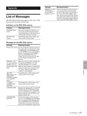
.... Take the necessary measures shown below. Reset the pan/tilt position or turn the power off the power of the camera, and consult with your Sony dealer. *[ENTER]: EXIT This message appears while you store the camera settings into (xx = preset position the memory (POSITION 1-16), the numbers 01 ... Remote Control Unit to an error in the SYSTEM menu. The changed the setting of the joystick on the screen. Wait for the BRC-Z330 camera Message Meaning/remedies Please restart system You are prompted to restart the power of the camera after moving due to turn off the ...
.... Take the necessary measures shown below. Reset the pan/tilt position or turn the power off the power of the camera, and consult with your Sony dealer. *[ENTER]: EXIT This message appears while you store the camera settings into (xx = preset position the memory (POSITION 1-16), the numbers 01 ... Remote Control Unit to an error in the SYSTEM menu. The changed the setting of the joystick on the screen. Wait for the BRC-Z330 camera Message Meaning/remedies Please restart system You are prompted to restart the power of the camera after moving due to turn off the ...
Operating Instructions
Page 70
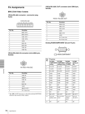
Pin Assignments BRC-Z330 Video Camera VISCA RS-422 connector (connector plug 9-pin) VISCA RS-422 123456789 Pin No. 1 2 3 4 5 6 7 8 9 Function RXD OUT - VISCA RS-232C OUT connector (mini DIN 8-...
Pin Assignments BRC-Z330 Video Camera VISCA RS-422 connector (connector plug 9-pin) VISCA RS-422 123456789 Pin No. 1 2 3 4 5 6 7 8 9 Function RXD OUT - VISCA RS-232C OUT connector (mini DIN 8-...
Operating Instructions
Page 72
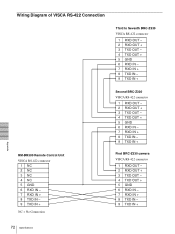
Wiring Diagram of VISCA RS-422 Connection Third to Seventh BRC-Z330 VISCA RS-422 connector 1 RXD OUT - 2 RXD OUT + 3 TXD OUT - 4 TXD OUT + 5 GND 6 RXD IN - 7 RXD IN + 8 TXD IN - 9 TXD IN + RM-BR300 Remote Control ...Unit VISCA RS-422 connector 1 NC 2 NC 3 NC 4 NC 5 GND 6 RXD IN - 7 RXD IN + 8 TXD IN - 9 TXD IN + NC = No Connection Second BRC-Z330 VISCA RS-422 connector 1 RXD OUT - 2 RXD OUT + 3 TXD OUT - 4 TXD OUT + 5 GND 6 RXD IN - 7 RXD IN + 8 TXD IN - 9 TXD IN + First...
Wiring Diagram of VISCA RS-422 Connection Third to Seventh BRC-Z330 VISCA RS-422 connector 1 RXD OUT - 2 RXD OUT + 3 TXD OUT - 4 TXD OUT + 5 GND 6 RXD IN - 7 RXD IN + 8 TXD IN - 9 TXD IN + RM-BR300 Remote Control ...Unit VISCA RS-422 connector 1 NC 2 NC 3 NC 4 NC 5 GND 6 RXD IN - 7 RXD IN + 8 TXD IN - 9 TXD IN + NC = No Connection Second BRC-Z330 VISCA RS-422 connector 1 RXD OUT - 2 RXD OUT + 3 TXD OUT - 4 TXD OUT + 5 GND 6 RXD IN - 7 RXD IN + 8 TXD IN - 9 TXD IN + First...