
Operating Instructions
Page 1
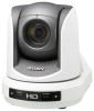
Printed on recycled paper. Sony Corporation 4-149-933-11 (1) HD Color Video Camera Printed in Japan Operating Instructions Before operating the unit, please read this manual thoroughly and retain it for future reference. BRC-Z330 © 2009 Sony Corporation
Printed on recycled paper. Sony Corporation 4-149-933-11 (1) HD Color Video Camera Printed in Japan Operating Instructions Before operating the unit, please read this manual thoroughly and retain it for future reference. BRC-Z330 © 2009 Sony Corporation
Operating Instructions
Page 3
...the Power 31 Pan/Tilt and Zoom Operation 32 Panning and Tilting 32 Zooming 33 Operating Multiple Cameras with the Remote Commander 33 Adjusting the Camera 33 Focusing on a Subject 39 Shooting with Back Lighting 40 Adjusting the White Balance 40 Adjusting...Features 7 System Components 8 Supplied Components and Accessories 8 Optional Products 9 System Configuration 10 Operating a BRC-Z330 Camera Using the Supplied Remote Commander 10 Operating a BRC-Z330 Camera Using the RM- Equipped with the Analog Component (YPbPr) Input Connector 52 Connecting a Device Equipped with VISCA ...
...the Power 31 Pan/Tilt and Zoom Operation 32 Panning and Tilting 32 Zooming 33 Operating Multiple Cameras with the Remote Commander 33 Adjusting the Camera 33 Focusing on a Subject 39 Shooting with Back Lighting 40 Adjusting the White Balance 40 Adjusting...Features 7 System Components 8 Supplied Components and Accessories 8 Optional Products 9 System Configuration 10 Operating a BRC-Z330 Camera Using the Supplied Remote Commander 10 Operating a BRC-Z330 Camera Using the RM- Equipped with the Analog Component (YPbPr) Input Connector 52 Connecting a Device Equipped with VISCA ...

Operating Instructions
Page 5
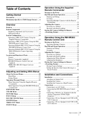
... CMOS image sensor. If abnormal noise occurs, consult with a lens cover. When the camera is not be exposed to sources of direct sunlight and other strong light or protect it with your Sony dealer. Close to laser beam radiation in quality. Locations subject to strong vibration or shock... • Use of a mobile phone close to heating equipment (e.g., near the camera. • Never expose the lens to the sun or...
... CMOS image sensor. If abnormal noise occurs, consult with a lens cover. When the camera is not be exposed to sources of direct sunlight and other strong light or protect it with your Sony dealer. Close to laser beam radiation in quality. Locations subject to strong vibration or shock... • Use of a mobile phone close to heating equipment (e.g., near the camera. • Never expose the lens to the sun or...
Operating Instructions
Page 6
... white flecks may be generated on the screen in rare cases, caused by cosmic rays, etc. It is made under lighting produced by turning the camera off and then on (see page 26). The white flecks especially tend to be seen in the following phenomena that may appear in the areas...
... white flecks may be generated on the screen in rare cases, caused by cosmic rays, etc. It is made under lighting produced by turning the camera off and then on (see page 26). The white flecks especially tend to be seen in the following phenomena that may appear in the areas...

Operating Instructions
Page 7
...high sensitivity and lower smear level. • Shooting an image using the menu or Remote Commander. 7 Features Multi-format HD outputs The camera supports output in 720P format (progressive scanning format with 720 effective scan lines) as well as to 1/4 or 1/16, using the 1080i...AE function The COLOR AE function enables automatic exposure adjustment for additional image output formats. The compactness and integration allow installation of the camera, which also allows switching between the 720/59.94P and 720/50P formats. An analog component signal output connector for HD output,...
...high sensitivity and lower smear level. • Shooting an image using the menu or Remote Commander. 7 Features Multi-format HD outputs The camera supports output in 720P format (progressive scanning format with 720 effective scan lines) as well as to 1/4 or 1/16, using the 1080i...AE function The COLOR AE function enables automatic exposure adjustment for additional image output formats. The compactness and integration allow installation of the camera, which also allows switching between the 720/59.94P and 720/50P formats. An analog component signal output connector for HD output,...
Operating Instructions
Page 8
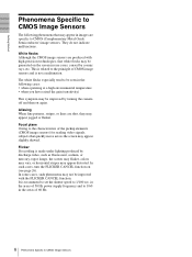
... available for the BRCZ330 HD Color Video Camera. Supplied Components and Accessories Before using the camera, make sure you have the following components and accessories supplied. Overview System Components In order to support multiple system configurations, a variety of optional products are not supplied. Ceiling bracket (A) (1) MPA-AC1 AC power adaptor (Sony) (1) Ceiling bracket (B) (1) AC...
... available for the BRCZ330 HD Color Video Camera. Supplied Components and Accessories Before using the camera, make sure you have the following components and accessories supplied. Overview System Components In order to support multiple system configurations, a variety of optional products are not supplied. Ceiling bracket (A) (1) MPA-AC1 AC power adaptor (Sony) (1) Ceiling bracket (B) (1) AC...
Operating Instructions
Page 9
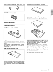
... (1 set), RS-422 connector plug (1), Power cord stopper (1), DC IN connector retainer (1) For details, consult with your Sony dealer. The Remote Control Unit also allows remote operation of up to SMPTE292M serial digital interface standardss. No audio signal is output from...(1), RS-232C connecting cable (3 m) (1), RS-422 connector plug (2) BRBK-HD2 HD-SDI Output Card This switcher can be used as a camera control, allowing camera operation such as pan/tilt and zoom operations. Overview Screw 3M3 × 8 (7)/Stainless screw 3M4 × 8 (1) Video Switcher (commercially ...
... (1 set), RS-422 connector plug (1), Power cord stopper (1), DC IN connector retainer (1) For details, consult with your Sony dealer. The Remote Control Unit also allows remote operation of up to SMPTE292M serial digital interface standardss. No audio signal is output from...(1), RS-232C connecting cable (3 m) (1), RS-422 connector plug (2) BRBK-HD2 HD-SDI Output Card This switcher can be used as a camera control, allowing camera operation such as pan/tilt and zoom operations. Overview Screw 3M3 × 8 (7)/Stainless screw 3M4 × 8 (1) Video Switcher (commercially ...
Operating Instructions
Page 10
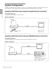
...) signal , Signal flow 10 System Configuration Overview Remote Commander (supplied) Video signal Signal flow Operating a BRC-Z330 Camera Using the RM-BR300 Remote Control Unit This system allows you : To operate the camera readily from a short distance System configuration BRC-Z330 HD video monitor, VTR, etc. Operating a BRC-Z330... Camera Using the Supplied Remote Commander This system allows you : To perform pan/tilt and zoom operations using optional products. This section ...
...) signal , Signal flow 10 System Configuration Overview Remote Commander (supplied) Video signal Signal flow Operating a BRC-Z330 Camera Using the RM-BR300 Remote Control Unit This system allows you : To operate the camera readily from a short distance System configuration BRC-Z330 HD video monitor, VTR, etc. Operating a BRC-Z330... Camera Using the Supplied Remote Commander This system allows you : To perform pan/tilt and zoom operations using optional products. This section ...
Operating Instructions
Page 11
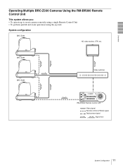
BRC-Z330 BRC-Z330 Video switcher RM-BR300 Remote Control Unit Video signal Remote control (VISCA) signal Tally/contact signal , Signal flow 11 System Configuration Overview Operating Multiple BRC-Z330 Cameras Using the RM-BR300 Remote Control Unit This system allows you: • To operate up to seven cameras remotely using a single Remote Control Unit • To perform pan/tilt and zoom operations using the joystick System configuration BRC-Z330 HD video monitor, VTR, etc.
BRC-Z330 BRC-Z330 Video switcher RM-BR300 Remote Control Unit Video signal Remote control (VISCA) signal Tally/contact signal , Signal flow 11 System Configuration Overview Operating Multiple BRC-Z330 Cameras Using the RM-BR300 Remote Control Unit This system allows you: • To operate up to seven cameras remotely using a single Remote Control Unit • To perform pan/tilt and zoom operations using the joystick System configuration BRC-Z330 HD video monitor, VTR, etc.
Operating Instructions
Page 12
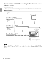
..., VTR, etc. BRBK-HD2 BRC-Z330 BRC-Z330 BRBK-HD2 BRBK-HD2 BRS-200 Processor Control cable (supplied with the BRS-200) BRS-200 REMOTE CAMERA OPERATING SWITCHER BRS-200 Control Panel Video signal Remote control (VISCA) signal , Signal flow Note To operate a BRC-Z330 with the BRS-200 Remote... Camera Operating Switcher, install an optional BRBK-HD2 HDSDI Output Card in the BRC-Z330, which cannot be controlled this way without a BRBK-HD2 HD-SDI ...
..., VTR, etc. BRBK-HD2 BRC-Z330 BRC-Z330 BRBK-HD2 BRBK-HD2 BRS-200 Processor Control cable (supplied with the BRS-200) BRS-200 REMOTE CAMERA OPERATING SWITCHER BRS-200 Control Panel Video signal Remote control (VISCA) signal , Signal flow Note To operate a BRC-Z330 with the BRS-200 Remote... Camera Operating Switcher, install an optional BRBK-HD2 HDSDI Output Card in the BRC-Z330, which cannot be controlled this way without a BRBK-HD2 HD-SDI ...
Operating Instructions
Page 13
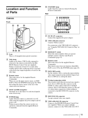
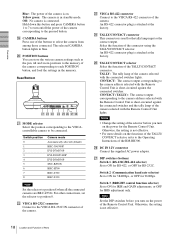
...OUT 13 Location and Function of Parts Set it to the VISCA RS-422 connector, see "Using the VISCA RS-422 Connector Plug" on the camera. L 75-ohm termination switch This switch is used when an external sync signal is a 18-magnification optical zoom lens. When you operate multiple... stopped regardless of on/off using the supplied AC power adaptor and AC power cord. H VISCA RS-422 connector Used for the supplied Remote Commander. D SONY and HD nameplates Pull them out to the RM-BR300 Remote Control Unit (not supplied). qfqg qhqj qk ql G DC IN 12V connector Connect the...
...OUT 13 Location and Function of Parts Set it to the VISCA RS-422 connector, see "Using the VISCA RS-422 Connector Plug" on the camera. L 75-ohm termination switch This switch is used when an external sync signal is a 18-magnification optical zoom lens. When you operate multiple... stopped regardless of on/off using the supplied AC power adaptor and AC power cord. H VISCA RS-422 connector Used for the supplied Remote Commander. D SONY and HD nameplates Pull them out to the RM-BR300 Remote Control Unit (not supplied). qfqg qhqj qk ql G DC IN 12V connector Connect the...
Operating Instructions
Page 14
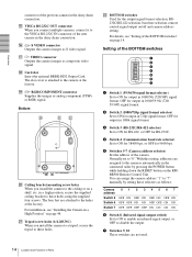
... in a high position, secure the supplied ceiling bracket to ON for 38400 bps, or OFF for 9600 bps. 5 Switches 5-7 (Camera address selector) Set the address of the previous camera in 1080i signal format. 3 Switch 3 (RS-232C/RS-422 selector) Set to ON for RS-422, or OFF for the ... RS232C/RS-422 selection, baud rate selection, remote control signal output on the RMBR300 Remote Control Unit. Overview connector of the camera. P S VIDEO connector Outputs the camera images as follows: Camera address Switch 5 Switch 6 Switch 7 012 34567 OFF ON OFF ON OFF ON OFF ON OFF OFF ON ON OFF OFF...
... in a high position, secure the supplied ceiling bracket to ON for 38400 bps, or OFF for 9600 bps. 5 Switches 5-7 (Camera address selector) Set the address of the previous camera in 1080i signal format. 3 Switch 3 (RS-232C/RS-422 selector) Set to ON for RS-422, or OFF for the ... RS232C/RS-422 selection, baud rate selection, remote control signal output on the RMBR300 Remote Control Unit. Overview connector of the camera. P S VIDEO connector Outputs the camera images as follows: Camera address Switch 5 Switch 6 Switch 7 012 34567 OFF ON OFF ON OFF ON OFF ON OFF OFF ON ON OFF OFF...

Operating Instructions
Page 15
...menu is selected, the display returns to the next menu one level higher. C DATA SCREEN button Press this button to change the set different camera numbers. If you press the button when a lower-level menu is displayed. B FOCUS buttons Used for focus adjustment. E L/R DIRECTION SET button...the menu is connected to display the main menu. H POSITION buttons Hold down the PRESET button and press button 1 to 6 to store the current camera direction, zooming, focus adjustment and backlight compensation in , and the W (wide angle) side to turn on/off the menu. I PAN-TILT RESET...
...menu is selected, the display returns to the next menu one level higher. C DATA SCREEN button Press this button to change the set different camera numbers. If you press the button when a lower-level menu is displayed. B FOCUS buttons Used for focus adjustment. E L/R DIRECTION SET button...the menu is connected to display the main menu. H POSITION buttons Hold down the PRESET button and press button 1 to 6 to store the current camera direction, zooming, focus adjustment and backlight compensation in , and the W (wide angle) side to turn on/off the menu. I PAN-TILT RESET...
Operating Instructions
Page 16
...DIRECTION POWER PANEL LIGHT BLACK PAN-TILT ONE PUSH LIGHT RESET AWB MENU POSITION 12345678 9 10 11 12 13 14 15 16 STD REV CAMERA 1234567 qhqjqk ql w; B VALUE/R control When the brightness adjustment mode is also disabled. When the white balance adjustment mode is selected with...and B indicators are lit. When the white balance adjustment mode is selected, the VALUE and BRIGHT indicators are lit. For operations with other cameras, refer to the white balance mode selected on page 41. When the VALUE indicator is selected with the MODE button (with the R indicator...
...DIRECTION POWER PANEL LIGHT BLACK PAN-TILT ONE PUSH LIGHT RESET AWB MENU POSITION 12345678 9 10 11 12 13 14 15 16 STD REV CAMERA 1234567 qhqjqk ql w; B VALUE/R control When the brightness adjustment mode is also disabled. When the white balance adjustment mode is selected with...and B indicators are lit. When the white balance adjustment mode is selected, the VALUE and BRIGHT indicators are lit. For operations with other cameras, refer to the white balance mode selected on page 41. When the VALUE indicator is selected with the MODE button (with the R indicator...
Operating Instructions
Page 17
.... J PANEL LIGHT button Press this button to disable the function. This function adjusts the exposure to 8. O Joystick When the menu of the camera is not displayed The joystick is illuminated. When you release the SHIFT button, the upper indicator lights and the POSITION buttons can be used for... smaller (zoom out). M ONE PUSH AWB button When ONE PUSH is used for menu operations. R POWER button Press this button to light the CAMERA button(s) corresponding to the direction in ). K BACK LIGHT button When FULL AUTO, SHUTTER Pri, IRIS Pri or GAIN Pri is cleared to select ...
.... J PANEL LIGHT button Press this button to disable the function. This function adjusts the exposure to 8. O Joystick When the menu of the camera is not displayed The joystick is illuminated. When you release the SHIFT button, the upper indicator lights and the POSITION buttons can be used for... smaller (zoom out). M ONE PUSH AWB button When ONE PUSH is used for menu operations. R POWER button Press this button to light the CAMERA button(s) corresponding to the direction in ). K BACK LIGHT button When FULL AUTO, SHUTTER Pri, IRIS Pri or GAIN Pri is cleared to select ...
Operating Instructions
Page 18
...wa ws wd wf wg wh wj wk U MODE selector Select the position corresponding to the VISCAcontrollable camera to position 8 when all the connected cameras are BRC-Z330s. Switch position 0 1 2 3 4 5 6 7 8 Camera mode Automatically selected (default) BRC-300/300P EVI-D70/D70P EVI-D100/D100P EVI-D30/D30P SNC...Z700 BRC-Z330 Note Set the selector to be connected. Overview Blue: The power of the camera is in standby mode. Yellow green: The camera is on the functions of the camera selected with the Remote Control Unit is short-circuited against the connected switcher. X TALLY/CONTACT ...
...wa ws wd wf wg wh wj wk U MODE selector Select the position corresponding to the VISCAcontrollable camera to position 8 when all the connected cameras are BRC-Z330s. Switch position 0 1 2 3 4 5 6 7 8 Camera mode Automatically selected (default) BRC-300/300P EVI-D70/D70P EVI-D100/D100P EVI-D30/D30P SNC...Z700 BRC-Z330 Note Set the selector to be connected. Overview Blue: The power of the camera is in standby mode. Yellow green: The camera is on the functions of the camera selected with the Remote Control Unit is short-circuited against the connected switcher. X TALLY/CONTACT ...
Operating Instructions
Page 20
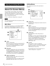
... With Menus Adjusting and Setting With Menus About On-Screen Menus You can change various settings, such as shooting conditions and system setup of the camera, while observing menus displayed on the RM-BR300 Remote Control Unit. >EXPOSURE COLOR PICTURE FOCUS PAN TILT ZOOM SYSTEM VIDEO OUT STATUS HD-SDI 1 ...button of the joystick on the RM-BR300. 3 Option Card indicator Displays the name of the output card inserted into the card slot of the camera. (The illustration above shows an example when the BRBK-HD2 HD-SDI Output Card is inserted.) Setting Menus The setting menu selected on the ...
... With Menus Adjusting and Setting With Menus About On-Screen Menus You can change various settings, such as shooting conditions and system setup of the camera, while observing menus displayed on the RM-BR300 Remote Control Unit. >EXPOSURE COLOR PICTURE FOCUS PAN TILT ZOOM SYSTEM VIDEO OUT STATUS HD-SDI 1 ...button of the joystick on the RM-BR300. 3 Option Card indicator Displays the name of the output card inserted into the card slot of the camera. (The illustration above shows an example when the BRBK-HD2 HD-SDI Output Card is inserted.) Setting Menus The setting menu selected on the ...
Operating Instructions
Page 21
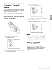
... by pressing the B or b button. If a lower-level menu is displayed, press the DATA SCREEN button once. Menu Operation Using the Supplied Remote Commander 1 POWER CAMERA SELECT 2 1 FOCUS 3 MANUAL NEAR BACK LIGHT FAR AUTO DATA SCREEN 3 REV 2 6 STD RESET 1 4 5 PRESET POSITIOPNAN-TILT HOME 2,4 SLOW 5 ZOOM PARNE-TSIELTT FAST T T W DIREL/CRTION SET...
... by pressing the B or b button. If a lower-level menu is displayed, press the DATA SCREEN button once. Menu Operation Using the Supplied Remote Commander 1 POWER CAMERA SELECT 2 1 FOCUS 3 MANUAL NEAR BACK LIGHT FAR AUTO DATA SCREEN 3 REV 2 6 STD RESET 1 4 5 PRESET POSITIOPNAN-TILT HOME 2,4 SLOW 5 ZOOM PARNE-TSIELTT FAST T T W DIREL/CRTION SET...
Operating Instructions
Page 22
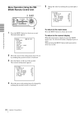
... SHIFT L/R DIRECTION POWER PANEL LIGHT BLACK PAN-TILT ONE PUSH LIGHT RESET AWB MENU POSITION 12345678 9 10 11 12 13 14 15 16 STD REV CAMERA 1234567 3 1 Press the MENU button for about one second. To return to the normal display When the main menu is displayed, press it pressed for...
... SHIFT L/R DIRECTION POWER PANEL LIGHT BLACK PAN-TILT ONE PUSH LIGHT RESET AWB MENU POSITION 12345678 9 10 11 12 13 14 15 16 STD REV CAMERA 1234567 3 1 Press the MENU button for about one second. To return to the normal display When the main menu is displayed, press it pressed for...

Operating Instructions
Page 24
...STD when CHECK is automatically adjusted. OFF: ND FILTER does not function. 1/4: Decrease the amount of light by 1/4. 1/16: Decrease the amount of the camera's built-in AUTO1 or AUTO2 mode. OUTDOOR: The R.GAIN and B.GAIN values are fixed to those for which the color of 5800K. WB R.SHIFT,... the following setting items that between NARROW and WIDE. MANUAL: Adjusts the white balance manually. When you switch the ND FILTER during shooting, camera image may be distorted. WB SENS: You can also adjust the red or blue tint when shooting an object under reddish light sources such...
...STD when CHECK is automatically adjusted. OFF: ND FILTER does not function. 1/4: Decrease the amount of light by 1/4. 1/16: Decrease the amount of the camera's built-in AUTO1 or AUTO2 mode. OUTDOOR: The R.GAIN and B.GAIN values are fixed to those for which the color of 5800K. WB R.SHIFT,... the following setting items that between NARROW and WIDE. MANUAL: Adjusts the white balance manually. When you switch the ND FILTER during shooting, camera image may be distorted. WB SENS: You can also adjust the red or blue tint when shooting an object under reddish light sources such...


