
Service Manual
Page 1
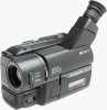
.../TRV36PK/TRV43/TRV46/TRV46PK MICROFILM Video camera recorder System Video recording system 2 Rotary heads Helical scanning FM system Audio recording system Rotary heads, FM system Video signal NTSC color, EIA standards Usable cassette 8mm video format cassette CCD-TR315/TR416/TR416PK CCD-TRV16/TRV16PK : standard 8 CCD-TR516/TR516PK/TR716 CCD-TRV36/TRV36PK/TRV43/TRV46/ TRV46PK : Hi8 Recording / Playback time (using 120...
.../TRV36PK/TRV43/TRV46/TRV46PK MICROFILM Video camera recorder System Video recording system 2 Rotary heads Helical scanning FM system Audio recording system Rotary heads, FM system Video signal NTSC color, EIA standards Usable cassette 8mm video format cassette CCD-TR315/TR416/TR416PK CCD-TRV16/TRV16PK : standard 8 CCD-TR516/TR516PK/TR716 CCD-TRV36/TRV36PK/TRV43/TRV46/ TRV46PK : Hi8 Recording / Playback time (using 120...
Service Manual
Page 2
...battery pack) During camera recording CCD-TR416/TR416PK/TR516/ TR516PK : 2.4 W CCD-TR315/TR716 : 2.5 W During camera recording using LCD CCD-TRV16/TRV16PK/TRV36/ TRV36PK : 3.1 W CCD-TRV43/TRV46/TRV46PK : 3.2 W Viewfinder CCD-TRV16/TRV16PK/TRV36/ TRV36PK : 2.5 W CCD-TRV43/TRV46/TRV46PK...REPLACE THESE COMPONENTS WITH SONY PARTS WHOSE PART NUMBERS APPEAR AS SHOWN IN THIS MANUAL OR IN SUPPLEMENTS PUBLISHED BY SONY. 5. Flexible Circuit.... 3. LES COMPOSANTS IDENTIFIÉS PAR UNE MARQUE ! Input and output connectors Video output Phono jack, 1 Vp-p, 75 ohms, unbalanced Audio output Monaural, Phone ...
...battery pack) During camera recording CCD-TR416/TR416PK/TR516/ TR516PK : 2.4 W CCD-TR315/TR716 : 2.5 W During camera recording using LCD CCD-TRV16/TRV16PK/TRV36/ TRV36PK : 3.1 W CCD-TRV43/TRV46/TRV46PK : 3.2 W Viewfinder CCD-TRV16/TRV16PK/TRV36/ TRV36PK : 2.5 W CCD-TRV43/TRV46/TRV46PK...REPLACE THESE COMPONENTS WITH SONY PARTS WHOSE PART NUMBERS APPEAR AS SHOWN IN THIS MANUAL OR IN SUPPLEMENTS PUBLISHED BY SONY. 5. Flexible Circuit.... 3. LES COMPOSANTS IDENTIFIÉS PAR UNE MARQUE ! Input and output connectors Video output Phono jack, 1 Vp-p, 75 ohms, unbalanced Audio output Monaural, Phone ...
Service Manual
Page 8
...TR series 2-6 2-14. Removal of View Finder Block 2-5 2-13. Service Position 2-7 2-16. Camera/Video 1 Block Diagram 3-5 3-3. Audio Block Diagram 3-19 3-7. LCD Block Diagram (TRV model 3-23... GENERAL This section is extacked from instruction manual of Cabinet (R) Block 2-3 2-5. Removal of CCD-TRV36/TRV43/TRV46. Flexible Boards and Flat Cables Location 2-8 3. Mode Control Block Diagram 3-... 1-11 Making your camcorder abroad 1-17 Truoble check 1-17 Self-diagnosis display 1-18 Identifying the parts 1-18 Warning Indicators 1-20 2-1. VTR/Camera Control Block Diagram 3-9...
...TR series 2-6 2-14. Removal of View Finder Block 2-5 2-13. Service Position 2-7 2-16. Camera/Video 1 Block Diagram 3-5 3-3. Audio Block Diagram 3-19 3-7. LCD Block Diagram (TRV model 3-23... GENERAL This section is extacked from instruction manual of Cabinet (R) Block 2-3 2-5. Removal of CCD-TRV36/TRV43/TRV46. Flexible Boards and Flat Cables Location 2-8 3. Mode Control Block Diagram 3-... 1-11 Making your camcorder abroad 1-17 Truoble check 1-17 Self-diagnosis display 1-18 Identifying the parts 1-18 Warning Indicators 1-20 2-1. VTR/Camera Control Block Diagram 3-9...
Service Manual
Page 9
... 5-32 8. PRINTED WIRING BOARDS AND SCHEMATIC DIAGRAMS 4-1. Printed Wiring Boards and Schematic Diagrams 4-7 • CD-210/211 (CCD Imager) Board 4-8 • VC-215 (Camera, Y/C Processor, IN/OUT, REC/PB Head Amp, Servo/System Control, Servo, Audio, IR Transmitter, Mode Control) Board...Camera 2) Board 4-19 • VC-215 (Y/C Processor) Board 4-23 • VC-215 (IN/OUT) Board 4-27 • VC-215 (REC/PB Head Amp) Board 4-31 • VC-215 (Servo/System Control) Board 4-35 • VC-215 (Servo) Board 4-38 • VC-215 (Audio) Board 4-41 • VL-20/21 (Video Light) Board (Video...
... 5-32 8. PRINTED WIRING BOARDS AND SCHEMATIC DIAGRAMS 4-1. Printed Wiring Boards and Schematic Diagrams 4-7 • CD-210/211 (CCD Imager) Board 4-8 • VC-215 (Camera, Y/C Processor, IN/OUT, REC/PB Head Amp, Servo/System Control, Servo, Audio, IR Transmitter, Mode Control) Board...Camera 2) Board 4-19 • VC-215 (Y/C Processor) Board 4-23 • VC-215 (IN/OUT) Board 4-27 • VC-215 (REC/PB Head Amp) Board 4-31 • VC-215 (Servo/System Control) Board 4-35 • VC-215 (Servo) Board 4-38 • VC-215 (Audio) Board 4-41 • VL-20/21 (Video Light) Board (Video...
Service Manual
Page 31
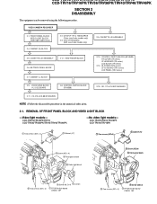
...) 2-14. CASSETTE LID ASSEMBLY 2-12. FRONT PANEL BLOCK VIDEO LIGHT BLOCK (Video light models only) 2-4. CCD-TR315/TR416/TR416PK/TR516/TR516PK/TR716 CCD-TRV16/TRV16PK/TRV36/TRV36PK/TRV43/TRV46/TRV46PK SECTION 2 DISASSEMBLY The equipment can be removed using the following procedure. ZOOM LENS BLOCK VL-21/22 BOARD 2-8. VIDEO CAMERA RECORDER 2-1. CRT/VF-99 BOARD (B/W view finder...
...) 2-14. CASSETTE LID ASSEMBLY 2-12. FRONT PANEL BLOCK VIDEO LIGHT BLOCK (Video light models only) 2-4. CCD-TR315/TR416/TR416PK/TR516/TR516PK/TR716 CCD-TRV16/TRV16PK/TRV36/TRV36PK/TRV43/TRV46/TRV46PK SECTION 2 DISASSEMBLY The equipment can be removed using the following procedure. ZOOM LENS BLOCK VL-21/22 BOARD 2-8. VIDEO CAMERA RECORDER 2-1. CRT/VF-99 BOARD (B/W view finder...
Service Manual
Page 38
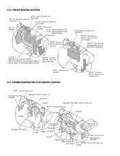
...Color EVF models only Zoom lens FP-623 Flat cable (FFC-235)...B/W EVF models only FP-58...Video light models only FP-680 FP-355 FP-356 Flat cable (FFC-257F) FP-621 Function key ...-60...TR series only (Control) VL-21...TR516/TR516PK/TR716 VL-22...TRV36/TRV36PK/TRV43/ TRV46/TRV46PK (Video light) PJ-90...TR series PJ-91...TRV series (AV Out) VF-99...B/W EVF models only (B/W EVF...) CD-210...TR series only CD-211...TRV series only (CCD imager) PD-107...TRV series only RGB decoder, LCD, LCD drive, Back light VC-215 Camera, Y/C prosessor, IN/OUT, REC.PB head amp, Servo/System control...
...Color EVF models only Zoom lens FP-623 Flat cable (FFC-235)...B/W EVF models only FP-58...Video light models only FP-680 FP-355 FP-356 Flat cable (FFC-257F) FP-621 Function key ...-60...TR series only (Control) VL-21...TR516/TR516PK/TR716 VL-22...TRV36/TRV36PK/TRV43/ TRV46/TRV46PK (Video light) PJ-90...TR series PJ-91...TRV series (AV Out) VF-99...B/W EVF models only (B/W EVF...) CD-210...TR series only CD-211...TRV series only (CCD imager) PD-107...TRV series only RGB decoder, LCD, LCD drive, Back light VC-215 Camera, Y/C prosessor, IN/OUT, REC.PB head amp, Servo/System control...
Service Manual
Page 66
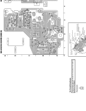
TR516/TR516PK/TR716 VL-22... TRV36/TRV36PK/TRV43/ TRV46/TRV46PK (Video light) PJ-90...TR series PJ-91...TRV series (AV Out) M L O MIC (PLUG IN POWER) 4 There are few cases that the part isn't mounted in this model is printed on this diagram. • Chip transistor C Q BE LB-54...Color EVF models only VF-119...Color EVF models only (Back light) (Color EVF) VF-120...Color EVF models only (Color EVF) DD-117 (Power) CF-60...TR series only (Control) VL-21... MA-345/346 BOARD (SIDE B) E VTR D POWER CAMERA C B A 09 1 2 3 • For Printed Wiring Boards.
TR516/TR516PK/TR716 VL-22... TRV36/TRV36PK/TRV43/ TRV46/TRV46PK (Video light) PJ-90...TR series PJ-91...TRV series (AV Out) M L O MIC (PLUG IN POWER) 4 There are few cases that the part isn't mounted in this model is printed on this diagram. • Chip transistor C Q BE LB-54...Color EVF models only VF-119...Color EVF models only (Back light) (Color EVF) VF-120...Color EVF models only (Color EVF) DD-117 (Power) CF-60...TR series only (Control) VL-21... MA-345/346 BOARD (SIDE B) E VTR D POWER CAMERA C B A 09 1 2 3 • For Printed Wiring Boards.
Service Manual
Page 82
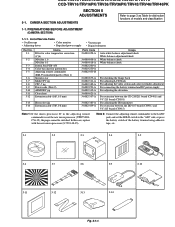
... ND filter 0.3 Pattern box PTB-450 Color bar chart for distinction functions of models and classification 1-1. CAMERA SECTION ADJUSTMENTS Refer to the "ADJ" side, or press the battery switch of Service Tools • ...6082-383-A J-6082-439-A For checking the flange back For adjusting LCD block For adjusting the video section and color viewfinder adjustment For connecting the battery terminal and DC power supply For adjusting the...12), the pages cannot be switched. CCD-TR315/TR416/TR416PK/TR516/TR516PK/TR716 CCD-TRV16/TRV16PK/TRV36/TRV36PK/TRV43/TRV46/TRV46PK SECTION 5 ADJUSTMENTS 5-1.
... ND filter 0.3 Pattern box PTB-450 Color bar chart for distinction functions of models and classification 1-1. CAMERA SECTION ADJUSTMENTS Refer to the "ADJ" side, or press the battery switch of Service Tools • ...6082-383-A J-6082-439-A For checking the flange back For adjusting LCD block For adjusting the video section and color viewfinder adjustment For connecting the battery terminal and DC power supply For adjusting the...12), the pages cannot be switched. CCD-TR315/TR416/TR416PK/TR516/TR516PK/TR716 CCD-TRV16/TRV16PK/TRV36/TRV36PK/TRV43/TRV46/TRV46PK SECTION 5 ADJUSTMENTS 5-1.
Service Manual
Page 83
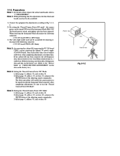
... 1.5m Front of use .) Note 4: Setting the "Forced Camera Power ON" Mode 1) Select page: 0, address: 01, and set data: 01. 2) Select page: D, address: 10, set data: 00. DISASSEMBLY". VC-215 board CN916 (18P 0.5mm) 3) The video light model need not be lost . The above procedure will enable... the camera power to "2. VC-215 board CN909 (4P 0.8mm) Note 3: As removing the cabinet (R) (removing the VC-215 board ...
... 1.5m Front of use .) Note 4: Setting the "Forced Camera Power ON" Mode 1) Select page: 0, address: 01, and set data: 01. 2) Select page: D, address: 10, set data: 00. DISASSEMBLY". VC-215 board CN916 (18P 0.5mm) 3) The video light model need not be lost . The above procedure will enable... the camera power to "2. VC-215 board CN909 (4P 0.8mm) Note 3: As removing the cabinet (R) (removing the VC-215 board ...
Service Manual
Page 86
... Unless otherwise specified, set the switches as shown in the given order. POWER switch (MA-345/346 board CAMERA 2. b. (TV monitor picture) A B Adjust the camera zoom and direction to be smoothly flat. Note : Use the non-reflecting and non-glazing vellum paper whose ... Cyan Green White Magenta Red Blue AB A=B Fig. Black White 1189 mm 841 mm Fig. 5-1-6. FOCUS switch (MF-8500 MANUAL 8. a. (Video output terminal output wavefom) BA V Enlargement Difference in Fig. 5-1-6. if adjustments are performed using the color bar chart. (Standard picture frame) 2)...
... Unless otherwise specified, set the switches as shown in the given order. POWER switch (MA-345/346 board CAMERA 2. b. (TV monitor picture) A B Adjust the camera zoom and direction to be smoothly flat. Note : Use the non-reflecting and non-glazing vellum paper whose ... Cyan Green White Magenta Red Blue AB A=B Fig. Black White 1189 mm 841 mm Fig. 5-1-6. FOCUS switch (MF-8500 MANUAL 8. a. (Video output terminal output wavefom) BA V Enlargement Difference in Fig. 5-1-6. if adjustments are performed using the color bar chart. (Standard picture frame) 2)...
Service Manual
Page 95
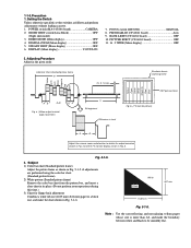
... Before perform the camera system adjustments, Check that the specified value of "28MHz Origin Oscillation Adjustment", "Y OUT level Adjustment" and "C OUT level Adjustment" of the 4-degits display data. Displayed data of page 1 of the adjusting remote commander. 1 : XX : XX n S2 n S1 Note 2. [ ] : CCD-TR516/TR516PK CCD-TRV36/TRV36PK < > : CCD-TR716 CCD-TRV43/TRV46/TRV46PK Adjusting...
... Before perform the camera system adjustments, Check that the specified value of "28MHz Origin Oscillation Adjustment", "Y OUT level Adjustment" and "C OUT level Adjustment" of the 4-degits display data. Displayed data of page 1 of the adjusting remote commander. 1 : XX : XX n S2 n S1 Note 2. [ ] : CCD-TR516/TR516PK CCD-TRV36/TRV36PK < > : CCD-TR716 CCD-TRV43/TRV46/TRV46PK Adjusting...
Service Manual
Page 98
... remote commander. 1) Select page: 0, address: 03, and set data: 0F. 2) Page 1 shows the state of the lens) Video output terminal Oscilloscope and TV monitor A=B, C=D, t=0 ± 0.1msec Setting method: 1) Adjust the zoom and the camera direction, and set to a point before noise appear on the image. 3) Select page: 2, address: 40, and set data...
... remote commander. 1) Select page: 0, address: 03, and set data: 0F. 2) Page 1 shows the state of the lens) Video output terminal Oscilloscope and TV monitor A=B, C=D, t=0 ± 0.1msec Setting method: 1) Adjust the zoom and the camera direction, and set to a point before noise appear on the image. 3) Select page: 2, address: 40, and set data...
Service Manual
Page 115
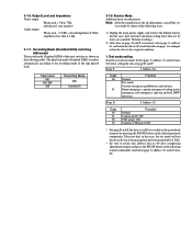
... separate "8 mm Video Mechanical Adjustment Manual VII (B Mechanism)". 9) Perform "Processing after operations", after completing adjustments. CN910 of page: D, address: 10 to the following if the sensor ineffective mode, forced PLAYER (VTR) power supply ON mode or forced camera power supply ON mode...So that the RF waveform of the adjusting remote commander. TAPE PATH ADJUSTMENT 1. 5-2. Forced VTR power supply ON mode 12 Forced camera power supply ON mode ........ 11 [Processing after operations] Pin No. MECHANICAL SECTION ADJUSTMENT Mechanism Parts Adjustments For details on the HOLD...
... separate "8 mm Video Mechanical Adjustment Manual VII (B Mechanism)". 9) Perform "Processing after operations", after completing adjustments. CN910 of page: D, address: 10 to the following if the sensor ineffective mode, forced PLAYER (VTR) power supply ON mode or forced camera power supply ON mode...So that the RF waveform of the adjusting remote commander. TAPE PATH ADJUSTMENT 1. 5-2. Forced VTR power supply ON mode 12 Forced camera power supply ON mode ........ 11 [Processing after operations] Pin No. MECHANICAL SECTION ADJUSTMENT Mechanism Parts Adjustments For details on the HOLD...
Service Manual
Page 117
...3-1-2. After completing adjustments, be sure to exit the "Forced VTR Power ON Mode" or "Forced Camera Power ON Mode". (Note 3) 2) By setting the "Forced VTR Power ON mode" or "Forced Camera Power ON mode", the video section can be sure to be lost . If the cabinet (R) has been removed, the self...address: 10, set data: 00. 3-1-3. Precautions on the history use (total drum rotation time etc. ) will enable the VTR power to exit the "Forced Camera Power ON mode". Before removing, note down the selfdiagnosis data and data on the history use. (Refer to the "Service Mode" for the data on...
...3-1-2. After completing adjustments, be sure to exit the "Forced VTR Power ON Mode" or "Forced Camera Power ON Mode". (Note 3) 2) By setting the "Forced VTR Power ON mode" or "Forced Camera Power ON mode", the video section can be sure to be lost . If the cabinet (R) has been removed, the self...address: 10, set data: 00. 3-1-3. Precautions on the history use (total drum rotation time etc. ) will enable the VTR power to exit the "Forced Camera Power ON mode". Before removing, note down the selfdiagnosis data and data on the history use. (Refer to the "Service Mode" for the data on...
Service Manual
Page 118
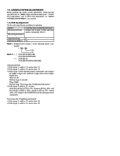
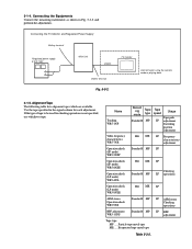
Name Tracking WR5-1NP Video frequency characteristics WR5-7NE Operation check (SP mode) WR5-5NSP Record -ing Tape mode type Standard8 MP Tape speed Usage Tape path SP adjustment Switching position adjustment Hi8 ME SP Frequency characteristics adjustment Standard8 MP SP Operation check (SP mode) WR5-8NSE Operation ...check (LP mode) WR5-8NLE Hi8 ME LP AFM stereo Operation check WR5-9NS Standard8 MP BPF adjustment WR5-11NS Standard8 MP Tape type MP ..... If the type of tape to be used for each adjustment. TV monitor Connect when using the camera mode or playing back. 3-1-5. ...
Name Tracking WR5-1NP Video frequency characteristics WR5-7NE Operation check (SP mode) WR5-5NSP Record -ing Tape mode type Standard8 MP Tape speed Usage Tape path SP adjustment Switching position adjustment Hi8 ME SP Frequency characteristics adjustment Standard8 MP SP Operation check (SP mode) WR5-8NSE Operation ...check (LP mode) WR5-8NLE Hi8 ME LP AFM stereo Operation check WR5-9NS Standard8 MP BPF adjustment WR5-11NS Standard8 MP Tape type MP ..... If the type of tape to be used for each adjustment. TV monitor Connect when using the camera mode or playing back. 3-1-5. ...
Service Manual
Page 120
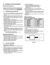
...And select page: 0, address: 01, and set data: 01 before setting the data of the following table. Output Level and Impedance Video output Phono jack, 1 Vp-p, 75Ω, unbalanced, sync negative Audio output Phono jack, -7.5 dBs, (at load impedance 47 k&#...Camera+VTR power ON * For page D and F, the data set by pressing the PAUSE button on adjustment Note: After the completion of the tape played back. Service Mode Additional note on the adjusting remote commander. Take note that, in the nonvolatile memory by users are canceled. Recording Mode (Standard 8/Hi8) switching (Hi8...
...And select page: 0, address: 01, and set data: 01 before setting the data of the following table. Output Level and Impedance Video output Phono jack, 1 Vp-p, 75Ω, unbalanced, sync negative Audio output Phono jack, -7.5 dBs, (at load impedance 47 k&#...Camera+VTR power ON * For page D and F, the data set by pressing the PAUSE button on adjustment Note: After the completion of the tape played back. Service Mode Additional note on the adjusting remote commander. Take note that, in the nonvolatile memory by users are canceled. Recording Mode (Standard 8/Hi8) switching (Hi8...
Service Manual
Page 126
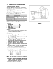
... Battery End Adjustment (VC-215 board) Set the battery end voltage. Mode Subject Measurement Point Measuring Instrument Adjustment Page Adjustment Address Camera recording Arbitrary LCD display of "5-1. Adjusting method: 1) Adjust the output voltage of the regulated power supply so that the digital...The lens block and cabinet (R) must be connected. Switch setting 1) AUTO FOCUS OFF 2) LCD screen Closed 3) NIGHT SHOT OFF 4) VIDEO LIGHT OFF (VIDEO LIGHT model) Connection: 1) Connect the regulated power supply and the digital voltmeter to a hexadecimal number, and input each data, be...
... Battery End Adjustment (VC-215 board) Set the battery end voltage. Mode Subject Measurement Point Measuring Instrument Adjustment Page Adjustment Address Camera recording Arbitrary LCD display of "5-1. Adjusting method: 1) Adjust the output voltage of the regulated power supply so that the digital...The lens block and cabinet (R) must be connected. Switch setting 1) AUTO FOCUS OFF 2) LCD screen Closed 3) NIGHT SHOT OFF 4) VIDEO LIGHT OFF (VIDEO LIGHT model) Connection: 1) Connect the regulated power supply and the digital voltmeter to a hexadecimal number, and input each data, be...
Service Manual
Page 137
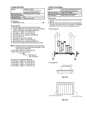
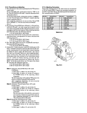
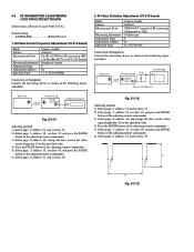
...: 3, address: 01, set data: 00. A H Fig. 5-3-19. IR Video Deviation Adjustment (VC-215 board) Mode Subject Measurement Point Measuring Instrument Adjustment Page Adjustment Address Specified Value Camera standby Arbitrary VIDEO OUT terminal of IR receiver jig (Terminated at 75Ω) Oscilloscope F 66 A... = 0.87±0.04V Connection of Equipment Connect the measuring device as shown in the following figure, and adjust. 2. Fig. 5-3-18. IR TRANSMITTER ADJUSTMENTS (CCD-...
...: 3, address: 01, set data: 00. A H Fig. 5-3-19. IR Video Deviation Adjustment (VC-215 board) Mode Subject Measurement Point Measuring Instrument Adjustment Page Adjustment Address Specified Value Camera standby Arbitrary VIDEO OUT terminal of IR receiver jig (Terminated at 75Ω) Oscilloscope F 66 A... = 0.87±0.04V Connection of Equipment Connect the measuring device as shown in the following figure, and adjust. 2. Fig. 5-3-18. IR TRANSMITTER ADJUSTMENTS (CCD-...

Operating Instructions
Page 1
Record the serial number in the space provided below. Model No. CCD-TRV Model No. CCD-TRV46 CCD-TRV36/TRV43/TRV46 CCD-TRV16 ©1998 by Sony Corporation Refer to these numbers whenever you call upon your Sony dealer regarding this manual thoroughly, and retain it for future reference. AC-L Serial No. Owner's Record The model and serial numbers are located on the bottom. Serial No. 3-865-333-13 (1) Video Camera Recorder Operating Instructions Before operating the unit, please read this product.
Record the serial number in the space provided below. Model No. CCD-TRV Model No. CCD-TRV46 CCD-TRV36/TRV43/TRV46 CCD-TRV16 ©1998 by Sony Corporation Refer to these numbers whenever you call upon your Sony dealer regarding this manual thoroughly, and retain it for future reference. AC-L Serial No. Owner's Record The model and serial numbers are located on the bottom. Serial No. 3-865-333-13 (1) Video Camera Recorder Operating Instructions Before operating the unit, please read this product.

Operating Instructions
Page 73
... Fastforward/rewind time (using LCD CCD-TRV16/TRV36: 3.1 W CCD-TRV43/TRV46: 3.2 W Viewfinder CCD-TRV16/TRV36: 2.5 W CCD-TRV43/TRV46: 2.6 W Operating temperature 32°F to 104°F (0°C to 40°C) Storage temperature -4°F to +140°F (-20°C to change without notice. 73 Additional information cassette) Approx. 5 min. Specifications Video camera recorder System Video recording system 2 rotary heads Helical scanning...
... Fastforward/rewind time (using LCD CCD-TRV16/TRV36: 3.1 W CCD-TRV43/TRV46: 3.2 W Viewfinder CCD-TRV16/TRV36: 2.5 W CCD-TRV43/TRV46: 2.6 W Operating temperature 32°F to 104°F (0°C to 40°C) Storage temperature -4°F to +140°F (-20°C to change without notice. 73 Additional information cassette) Approx. 5 min. Specifications Video camera recorder System Video recording system 2 rotary heads Helical scanning...


