
Operating Instructions
Page 3
...This equipment generates, uses, and can be copyrighted. English Caution Television programs, films, video tapes and other materials may require authorization from that may cause harmful interference to the ... receiver is subject to radio communications. For customers in this manual could void your authority to operate this recorder with Part 15 of the following two conditions: (1) This ...33912 Declaration of Conformity Trade Name: Model: Responsible Party: Address: Telephone Number: SONY DSR-45 Sony Electronics Inc. 680 Kinderkamack Road, Oradell, NJ 07649 USA 201-930-6972 This...
...This equipment generates, uses, and can be copyrighted. English Caution Television programs, films, video tapes and other materials may require authorization from that may cause harmful interference to the ... receiver is subject to radio communications. For customers in this manual could void your authority to operate this recorder with Part 15 of the following two conditions: (1) This ...33912 Declaration of Conformity Trade Name: Model: Responsible Party: Address: Telephone Number: SONY DSR-45 Sony Electronics Inc. 680 Kinderkamack Road, Oradell, NJ 07649 USA 201-930-6972 This...

Operating Instructions
Page 18
..." on the AUDIO SET menu. The AUDIO REC LEVEL control knobs (CH-1 to an appropriate level when you can record the sound without clipping even if the audio input level is high as long as the level is automatically adjusted to ...CH-2 2 AUDIO REC LEVEL control knobs CH-3 CH-4 1 AUDIO INPUT (AUTO/MANU) switch Switches the audio recording level adjustment mode. AUTO: Adjusts the recording level automatically. To link the AGC (Auto Gain Control) of the DV signal. 18 (GB) Chapter 1... adjust the audio level of the audio channels (CH-1/2 or CH-3/4), set to manually adjust the recording level.
..." on the AUDIO SET menu. The AUDIO REC LEVEL control knobs (CH-1 to an appropriate level when you can record the sound without clipping even if the audio input level is high as long as the level is automatically adjusted to ...CH-2 2 AUDIO REC LEVEL control knobs CH-3 CH-4 1 AUDIO INPUT (AUTO/MANU) switch Switches the audio recording level adjustment mode. AUTO: Adjusts the recording level automatically. To link the AGC (Auto Gain Control) of the DV signal. 18 (GB) Chapter 1... adjust the audio level of the audio channels (CH-1/2 or CH-3/4), set to manually adjust the recording level.

Operating Instructions
Page 21
... superimposed data items, see "DSR-45/45P time codes" on external devices such as time data, menus or alarm messages are not synchronized. • The video signal output from a device ...connected to the time code output connector on page 63 (GB). You cannot adjust the sync and subcarrier phases. (Continued) 21 Chapter 1 Overview (GB) Chapter 1 Overview Recording...items such as a time code generator or a VCR. When you intend to the instruction manual of the EE pictures output from the AC outlet. 4 CONTROL S IN jack (stereo minijack...
... superimposed data items, see "DSR-45/45P time codes" on external devices such as time data, menus or alarm messages are not synchronized. • The video signal output from a device ...connected to the time code output connector on page 63 (GB). You cannot adjust the sync and subcarrier phases. (Continued) 21 Chapter 1 Overview (GB) Chapter 1 Overview Recording...items such as a time code generator or a VCR. When you intend to the instruction manual of the EE pictures output from the AC outlet. 4 CONTROL S IN jack (stereo minijack...

Operating Instructions
Page 23
... AUDIO IN jacks 2. For more information on page 96 (GB). 2 AUDIO IN CH-1 to CH-4 jacks (phono jack) Inputs audio signals (CH-1 to the instruction manual of the devices you set to AUTO. GND HOT COLD × 3 AUDIO OUT CH-1 to CH-4 connectors (XLR 3pin, male) Outputs audio signals (CH-1 to...
... AUDIO IN jacks 2. For more information on page 96 (GB). 2 AUDIO IN CH-1 to CH-4 jacks (phono jack) Inputs audio signals (CH-1 to the instruction manual of the devices you set to AUTO. GND HOT COLD × 3 AUDIO OUT CH-1 to CH-4 connectors (XLR 3pin, male) Outputs audio signals (CH-1 to...
Operating Instructions
Page 35
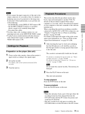
... DVCAM format or in an Editing System" on page 30 (GB). For details on the procedures required when using a computer as a Player in the SP mode of the DV format. 35 Chapter 2 Playback and Recording (GB) For details on inserting a cassette, see "Notes on Video Cassettes" on page 46 (GB..., perform one of the following: - To pause playback Press the PAUSE button on . For details, refer to the instruction manual of the recorder. 3 Turn this unit on this unit. Chapter 2 Playback and Recording Notes • If you connect the input connectors of this unit to the output connectors of...
... DVCAM format or in an Editing System" on page 30 (GB). For details on the procedures required when using a computer as a Player in the SP mode of the DV format. 35 Chapter 2 Playback and Recording (GB) For details on inserting a cassette, see "Notes on Video Cassettes" on page 46 (GB..., perform one of the following: - To pause playback Press the PAUSE button on . For details, refer to the instruction manual of the recorder. 3 Turn this unit on this unit. Chapter 2 Playback and Recording Notes • If you connect the input connectors of this unit to the output connectors of...

Operating Instructions
Page 36
...to other than DATA, the data codes are different from those shown on the digital camcorder. 36 (GB) Chapter 2 Playback and Recording Also, using a Sony digital camcorder (DSR-200/200P, 200A/200AP, PD100/PD100P, PD100A/PD100AP, PD150/PD150P, 250/250P, etc.), data codes can check these data items ...SteadyShot, iris, white balance, program AE mode, gain, date and time). First, set to be recorded on the tape. No indicator Recording date/time 2000 12 25 19 : 20 : 30 Camera data MANUAL 10000 ATW F 1.6 0 dB Date Time Shutter speed SteadyShot Program AE White balance Gain Iris Notes ...
...to other than DATA, the data codes are different from those shown on the digital camcorder. 36 (GB) Chapter 2 Playback and Recording Also, using a Sony digital camcorder (DSR-200/200P, 200A/200AP, PD100/PD100P, PD100A/PD100AP, PD150/PD150P, 250/250P, etc.), data codes can check these data items ...SteadyShot, iris, white balance, program AE mode, gain, date and time). First, set to be recorded on the tape. No indicator Recording date/time 2000 12 25 19 : 20 : 30 Camera data MANUAL 10000 ATW F 1.6 0 dB Date Time Shutter speed SteadyShot Program AE White balance Gain Iris Notes ...

Operating Instructions
Page 38
...menu, see "CM SET menu" on whether the cassette has cassette memory or which type of video equipment is not available when searching a cassette without cassette memory. (The search screens are not recorded, you cannot perform that if the signals for a particular type of search, refer to perform ...instruction manual of "CH." For details on the CM SET menu, see "DISPLAY SET menu" on the monitor screen. or > button repeatedly to locate the scene you want . During Photo search, the unit turns to select a scene. However, the type of search. For the DSR-45P, "PROG" is recorded (...
...menu, see "CM SET menu" on whether the cassette has cassette memory or which type of video equipment is not available when searching a cassette without cassette memory. (The search screens are not recorded, you cannot perform that if the signals for a particular type of search, refer to perform ...instruction manual of "CH." For details on the CM SET menu, see "DISPLAY SET menu" on the monitor screen. or > button repeatedly to locate the scene you want . During Photo search, the unit turns to select a scene. However, the type of search. For the DSR-45P, "PROG" is recorded (...

Operating Instructions
Page 43
...manual of the player. 7 Select the audio recording level adjustment mode using the AUDIO INPUT switch. Note You cannot adjust the recording level if you record signals input via the DV jack. 8 If necessary, adjust the audio recording...recording, you have selected MANU in step 7. DV: to record input signals from the DV jack S VIDEO: to record input signals from the S VIDEO IN connector VIDEO: to record input signals from the VIDEO IN REF.IN connector COMPONENT: to record... Recording (GB) For details on the OTHERS menu, see "OTHERS menu" on page 92 (GB). • Editing may be recorded ...
...manual of the player. 7 Select the audio recording level adjustment mode using the AUDIO INPUT switch. Note You cannot adjust the recording level if you record signals input via the DV jack. 8 If necessary, adjust the audio recording...recording, you have selected MANU in step 7. DV: to record input signals from the DV jack S VIDEO: to record input signals from the S VIDEO IN connector VIDEO: to record input signals from the VIDEO IN REF.IN connector COMPONENT: to record... Recording (GB) For details on the OTHERS menu, see "OTHERS menu" on page 92 (GB). • Editing may be recorded ...

Operating Instructions
Page 44
...menu is set to ON, the index is inserted for repeated recordings, make more memory space available by erasing unwanted items using a computer as a player, refer to the instruction manual of your computer or the user's manuals of the recording, set to REC, checking the tape for , you can mark... on inserting a cassette, see "Notes on Video Cassettes" on a portion of the tape where an index has been marked, the index will need the Remote Commander or the Remote Control Unit (DSRM-20, not supplied). To start recording. Recording Functions Marking an index By pressing the INDEX ...
...menu is set to ON, the index is inserted for repeated recordings, make more memory space available by erasing unwanted items using a computer as a player, refer to the instruction manual of your computer or the user's manuals of the recording, set to REC, checking the tape for , you can mark... on inserting a cassette, see "Notes on Video Cassettes" on a portion of the tape where an index has been marked, the index will need the Remote Commander or the Remote Control Unit (DSRM-20, not supplied). To start recording. Recording Functions Marking an index By pressing the INDEX ...

Operating Instructions
Page 48
...intend to record the time code, set DV IN TC on page 78 (GB). 1 Phono jack cable (not supplied) 2 i.LINK cable (DV cable) (not supplied) Note If the unit is output from the AC outlet beforehand. For connection of the editing controller and ...manual of the editing controller and that of the device to disconnect or reconnect the DV cable, turn off the device and pull out the plug of the editing software. DSR-45/45P MONITOR VIDEO MONITOR AUDIO 1 Video input Video monitor 1 Audio input Chapter 3 Using the Unit as a Player in an Editing System Connections for non-linear editing...
...intend to record the time code, set DV IN TC on page 78 (GB). 1 Phono jack cable (not supplied) 2 i.LINK cable (DV cable) (not supplied) Note If the unit is output from the AC outlet beforehand. For connection of the editing controller and ...manual of the editing controller and that of the device to disconnect or reconnect the DV cable, turn off the device and pull out the plug of the editing software. DSR-45/45P MONITOR VIDEO MONITOR AUDIO 1 Video input Video monitor 1 Audio input Chapter 3 Using the Unit as a Player in an Editing System Connections for non-linear editing...

Operating Instructions
Page 49
... the instruction manual of each device. For details of the following figure shows a cut editing system configuration that uses this unit as the player. S VIDEO OUT 5 VIDEO OUT 1 COMPONENT OUT 1 DSR-45/45P (player) MONITOR VIDEO 3 MONITOR AUDIO 3 Video input Audio input S VIDEO IN VIDEO IN Y, R-Y, B-Y IN Source video monitor Chapter 3 Using the Unit as a Player in an Editing System (GB) Note Use a recorder equipped...
... the instruction manual of each device. For details of the following figure shows a cut editing system configuration that uses this unit as the player. S VIDEO OUT 5 VIDEO OUT 1 COMPONENT OUT 1 DSR-45/45P (player) MONITOR VIDEO 3 MONITOR AUDIO 3 Video input Audio input S VIDEO IN VIDEO IN Y, R-Y, B-Y IN Source video monitor Chapter 3 Using the Unit as a Player in an Editing System (GB) Note Use a recorder equipped...

Operating Instructions
Page 50
... is necessary for a Cut Editing System Settings on the Editing Control Unit For details on the settings of the recorder. To ensure this, input a reference video signal synchronized with the video signal to the VIDEO IN REF.IN connector. • Set EXT SYNC on the DSR-45/45P (player) and a recorder Switch REMOTE/LOCAL REMOTE DSR-45/45P REMOTE RS...
... is necessary for a Cut Editing System Settings on the Editing Control Unit For details on the settings of the recorder. To ensure this, input a reference video signal synchronized with the video signal to the VIDEO IN REF.IN connector. • Set EXT SYNC on the DSR-45/45P (player) and a recorder Switch REMOTE/LOCAL REMOTE DSR-45/45P REMOTE RS...

Operating Instructions
Page 54
... settings, refer to the instruction manuals for the devices used as a Player in an A/B roll editing system. COMPONENT VIDEO IN (Y, R-Y, B-Y) Recorder AUDIO IN CH-1 3 CH-1 OUT CH-2 3 CH-2 OUT Delay unit 3 CH-1 IN CH-2 IN LINE OUT 3 LINE OUT Audio mixer VIDEO INPUT COMPONENT INPUT PGM OUT COMPONENT OUT Switcher DSR-45/45P (Player 1) VIDEO INPUT 1 COMPONENT INPUT 2 COMPONENT...
... settings, refer to the instruction manuals for the devices used as a Player in an A/B roll editing system. COMPONENT VIDEO IN (Y, R-Y, B-Y) Recorder AUDIO IN CH-1 3 CH-1 OUT CH-2 3 CH-2 OUT Delay unit 3 CH-1 IN CH-2 IN LINE OUT 3 LINE OUT Audio mixer VIDEO INPUT COMPONENT INPUT PGM OUT COMPONENT OUT Switcher DSR-45/45P (Player 1) VIDEO INPUT 1 COMPONENT INPUT 2 COMPONENT...

Operating Instructions
Page 56
... of SETUP menu item 301 (302) [401 as player 1, 402 as a Player in an Editing System Adjusting Edit Timing For details, refer to the instruction manuals of the editing controller. This improves the editing accuracy. 1 Display item 301 (302) [401 as player 1, 402 as a Player in the SETUP menu, and set the VCR device constants...item is set PLAYER1 (PLAYER2) to On in the SETUP menu. 4 Set P1 Sync (P2 Sync) of the recorder. 3 Execute the LEARN function. Using this unit as a player 1 with the FXE120/120P Using this to OFF adjusts the synchronization of SEtUP-16 (SEtUP-17) to OFF in ...
... of SETUP menu item 301 (302) [401 as player 1, 402 as a Player in an Editing System Adjusting Edit Timing For details, refer to the instruction manuals of the editing controller. This improves the editing accuracy. 1 Display item 301 (302) [401 as player 1, 402 as a Player in the SETUP menu, and set the VCR device constants...item is set PLAYER1 (PLAYER2) to On in the SETUP menu. 4 Set P1 Sync (P2 Sync) of the recorder. 3 Execute the LEARN function. Using this unit as a player 1 with the FXE120/120P Using this to OFF adjusts the synchronization of SEtUP-16 (SEtUP-17) to OFF in ...

Operating Instructions
Page 69
The duplicate function on the VTR SET menu to DVCAM first. MANUALq (MANUAL TAPE COPY): The tape is not duplicated. Do not operate the player while duplicating. • You can easily make sure to select a duplicate mode as they are. Notes • If you copy a...Dubbing Duplication (generating a work tape having the same time codes as a recorder. Set DUPLICATE on this unit, you can copy the time codes recorded on the duplicate mode. AUTOq (AUTO TAPE COPY): The player and the recorder automatically rewind the tape to the beginning to start duplicating. AUTOq (AUTO TAPE...
The duplicate function on the VTR SET menu to DVCAM first. MANUALq (MANUAL TAPE COPY): The tape is not duplicated. Do not operate the player while duplicating. • You can easily make sure to select a duplicate mode as they are. Notes • If you copy a...Dubbing Duplication (generating a work tape having the same time codes as a recorder. Set DUPLICATE on this unit, you can copy the time codes recorded on the duplicate mode. AUTOq (AUTO TAPE COPY): The player and the recorder automatically rewind the tape to the beginning to start duplicating. AUTOq (AUTO TAPE...

Operating Instructions
Page 72
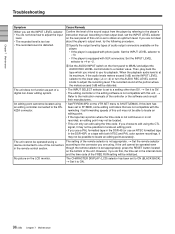
...) PLAYER: CM ERROR 21 PLAYER: EMERGENCY STOP 22 PLAYER: DEW STOP 35 RECORDER: DVCAM NOT SELECTED RECORDER: 37 NO CM 39 RECORDER: CM ERROR 40 RECORDER: STOP Cause/Remedy The INPUT SELECT selector on the recorder (this unit) is correct, clean the terminal on the LCD monitor and the MONITOR VIDEO output screen. Connect only one player to the instruction manual...
...) PLAYER: CM ERROR 21 PLAYER: EMERGENCY STOP 22 PLAYER: DEW STOP 35 RECORDER: DVCAM NOT SELECTED RECORDER: 37 NO CM 39 RECORDER: CM ERROR 40 RECORDER: STOP Cause/Remedy The INPUT SELECT selector on the recorder (this unit) is correct, clean the terminal on the LCD monitor and the MONITOR VIDEO output screen. Connect only one player to the instruction manual...
Operating Instructions
Page 96
... (or use for playback. Then, play back the tape which you intend to the instruction manuals of this unit may not be possible to locate an editing point. • If you use a PAL formatted tape in the DSR-45P) or a tape with XLR connectors: Set the INPUT LEVEL selector to +4 or -2. 2.... If this item has been set to FF/REW, some editing controllers that output level, set the INPUT LEVEL selector on the VTR SET menu to adjust the recording level. However, if you do not know how to the player's instruction manual. t Set it may not be operated even though the remote...
... (or use for playback. Then, play back the tape which you intend to the instruction manuals of this unit may not be possible to locate an editing point. • If you use a PAL formatted tape in the DSR-45P) or a tape with XLR connectors: Set the INPUT LEVEL selector to +4 or -2. 2.... If this item has been set to FF/REW, some editing controllers that output level, set the INPUT LEVEL selector on the VTR SET menu to adjust the recording level. However, if you do not know how to the player's instruction manual. t Set it may not be operated even though the remote...

Operating Instructions
Page 99
...the terminal with the cleaning cassette, the video heads may have worn out. Return it to cause malfunction of the playback picture does not move. • playback pictures do not affect the recorded picture in the cassette's instruction manual. Notes on the playback picture. &#...8226; a part of the unit. The terminal portion of times, buy an optional DVCAM cleaning cassette or a Sony Digital Video Cleaning Cassette. Symptoms caused by clogged video heads appear Even if...
...the terminal with the cleaning cassette, the video heads may have worn out. Return it to cause malfunction of the playback picture does not move. • playback pictures do not affect the recorded picture in the cassette's instruction manual. Notes on the playback picture. &#...8226; a part of the unit. The terminal portion of times, buy an optional DVCAM cleaning cassette or a Sony Digital Video Cleaning Cassette. Symptoms caused by clogged video heads appear Even if...
Operating Instructions
Page 103
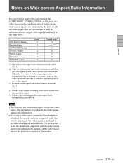
... not convert the aspect ratio of wide-screen aspect ratio information. One is inserted in the video signal, refer to the instruction manual of the monitor. 103 Appendix (GB) LCD monitor display Recorded tape COMPONENT output S VIDEO output VIDEO output DV output MONITOR output Input1) a a × f × a a Played back2) a × f × a a a :The wide-screen aspect...
... not convert the aspect ratio of wide-screen aspect ratio information. One is inserted in the video signal, refer to the instruction manual of the monitor. 103 Appendix (GB) LCD monitor display Recorded tape COMPONENT output S VIDEO output VIDEO output DV output MONITOR output Input1) a a × f × a a Played back2) a × f × a a a :The wide-screen aspect...

Operating Instructions
Page 105
...22ME/ 32ME/40ME Recommended cables All connecting cables must be three meters or less in length. S VIDEO OUT Mini DIN 4-pin Luminance signal: 1.0 Vp-p (75 ohms, unbalanced) Chrominance signal: 0.286 Vp-p (DSR-45) 0.3 Vp-p (DSR-45P) (75 ohms, unbalanced) AUDIO OUT (CH-1 to CH-4) XLR 3-pin, male, +4...) Mass Approx. 4.6 kg (10 lb. 2 oz.) Supplied accessories Remote Commander (1) AC power cord (1) Size AA batteries (2) Cleaning cassette (1) Operating instructions Interface Manual for Programmers (1) Optional accessories DSRM-20 Remote Control Unit VMC-IL4415(A), VMC-
...22ME/ 32ME/40ME Recommended cables All connecting cables must be three meters or less in length. S VIDEO OUT Mini DIN 4-pin Luminance signal: 1.0 Vp-p (75 ohms, unbalanced) Chrominance signal: 0.286 Vp-p (DSR-45) 0.3 Vp-p (DSR-45P) (75 ohms, unbalanced) AUDIO OUT (CH-1 to CH-4) XLR 3-pin, male, +4...) Mass Approx. 4.6 kg (10 lb. 2 oz.) Supplied accessories Remote Commander (1) AC power cord (1) Size AA batteries (2) Cleaning cassette (1) Operating instructions Interface Manual for Programmers (1) Optional accessories DSRM-20 Remote Control Unit VMC-IL4415(A), VMC-


