
Mounting Bracket Instruction Manual
Page 1
INSTALLATION MANUAL IN-SFM2.R1 SFM2 Sony Electronics, Inc. 16540 West Bernardo Drive San Diego, CA 92127 www.sony.com
INSTALLATION MANUAL IN-SFM2.R1 SFM2 Sony Electronics, Inc. 16540 West Bernardo Drive San Diego, CA 92127 www.sony.com
Mounting Bracket Instruction Manual
Page 2
Page - 2 - Installation Manual SFM2 Table of Contents WARNING STATEMENTS...- 3 PARTS LIST ...- 4 INSTALLATION TOOLS ...- 4 INSTALLATION PROCEDURES ...- 5 SINGLE STUD INSTALLATION ...- 5 SOLID STRUCTURE INSTALLATION ...- 6 ATTACHING THE ADAPTER PLATE AND THE BACKPLATE COVER 7 ATTACHING THE ADAPTER PLATE /BACKPLATE COVER TO THE DISPLAY 9 ATTACHING THE DISPLAY TO THE BACKPLATE 10 TECHNICAL SPECIFICATIONS ...- 11 WARRANTY ...- 12 CUSTOMER SUPPORT ...- 12 NOTES ...- 12 -
Page - 2 - Installation Manual SFM2 Table of Contents WARNING STATEMENTS...- 3 PARTS LIST ...- 4 INSTALLATION TOOLS ...- 4 INSTALLATION PROCEDURES ...- 5 SINGLE STUD INSTALLATION ...- 5 SOLID STRUCTURE INSTALLATION ...- 6 ATTACHING THE ADAPTER PLATE AND THE BACKPLATE COVER 7 ATTACHING THE ADAPTER PLATE /BACKPLATE COVER TO THE DISPLAY 9 ATTACHING THE DISPLAY TO THE BACKPLATE 10 TECHNICAL SPECIFICATIONS ...- 11 WARRANTY ...- 12 CUSTOMER SUPPORT ...- 12 NOTES ...- 12 -
Mounting Bracket Instruction Manual
Page 3
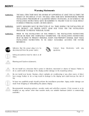
...at all times. FAILURE TO DO SO COULD RESULT IN SERIOUS PERSONAL INJURY, OR EVEN DEATH. Warning and Caution statements. Contact Sony Electronics with any surface other source of impact. At least two qualified people should perform the installation procedure. Do not install on...display. IF NOT, THE WALL STRUCTURE MUST BE REINFORCED. KEEP THESE INSTALLATION INSTRUCTIONS IN AN EASILY ACCESSIBLE LOCATION FOR FUTURE REFERENCE. Installation Manual Page - 3 - WARNING: WARNING: WARNING: SFM2 Warning Statements THE WALL STRUCTURE MUST BE CAPABLE OF SUPPORTING AT LEAST FIVE (5) TIMES ...
...at all times. FAILURE TO DO SO COULD RESULT IN SERIOUS PERSONAL INJURY, OR EVEN DEATH. Warning and Caution statements. Contact Sony Electronics with any surface other source of impact. At least two qualified people should perform the installation procedure. Do not install on...display. IF NOT, THE WALL STRUCTURE MUST BE REINFORCED. KEEP THESE INSTALLATION INSTRUCTIONS IN AN EASILY ACCESSIBLE LOCATION FOR FUTURE REFERENCE. Installation Manual Page - 3 - WARNING: WARNING: WARNING: SFM2 Warning Statements THE WALL STRUCTURE MUST BE CAPABLE OF SUPPORTING AT LEAST FIVE (5) TIMES ...

Mounting Bracket Instruction Manual
Page 4
If there are missing and/or damaged before beginning installation. Installation Manual Adapter Plate (Qty 1) Ultra Flat Mount (Qty 1) M4 x 10mm Phillips Pan Head Screw (Qty 4) M6 x 12mm Security Screws (Qty 2) M6 x 10mm Phillips Head Screws (Qty 4) #... with all proper installation hardware and components. After removing them, please store them in a safe location for possible future re-use with the following Sony models: SONY FWD-32LX1 FWD-32LX1R NOTE: Prior to installing the SFM2, the quick release sleeves (located on the back of these parts are parts missing and/or damaged, please...
If there are missing and/or damaged before beginning installation. Installation Manual Adapter Plate (Qty 1) Ultra Flat Mount (Qty 1) M4 x 10mm Phillips Pan Head Screw (Qty 4) M6 x 12mm Security Screws (Qty 2) M6 x 10mm Phillips Head Screws (Qty 4) #... with all proper installation hardware and components. After removing them, please store them in a safe location for possible future re-use with the following Sony models: SONY FWD-32LX1 FWD-32LX1R NOTE: Prior to installing the SFM2, the quick release sleeves (located on the back of these parts are parts missing and/or damaged, please...

Mounting Bracket Instruction Manual
Page 5
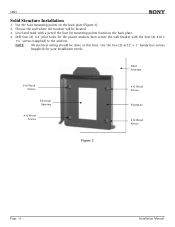
...single wood studs, use the two middle mounting points found on the marked wall. 4. Also, all the hardware listed in the LCD owners' manual. NOTE: Four wood screws will be done at (877) 350-3477. Locate the center of the wood stud by using two (2) #10... for your installation needs. #10 Wood Screws Wooden Stud Electrical Opening Frontplate #10 Wood Screw Figure 1 Installation Manual Page - 5 - If any precautions listed in the parts list (Page 5). Contact Sony Electronics immediately at this time. Use the two (2) 6/32" x 1" handy box screws (supplied) for ...
...single wood studs, use the two middle mounting points found on the marked wall. 4. Also, all the hardware listed in the LCD owners' manual. NOTE: Four wood screws will be done at (877) 350-3477. Locate the center of the wood stud by using two (2) #10... for your installation needs. #10 Wood Screws Wooden Stud Electrical Opening Frontplate #10 Wood Screw Figure 1 Installation Manual Page - 5 - If any precautions listed in the parts list (Page 5). Contact Sony Electronics immediately at this time. Use the two (2) 6/32" x 1" handy box screws (supplied) for ...
Mounting Bracket Instruction Manual
Page 6
NOTE: All electrical wiring should be located. 3. Installation Manual Choose the wall where the monitor will be done at this time. Use the four mounting points on the back plate. 4. Level and mark with ...
NOTE: All electrical wiring should be located. 3. Installation Manual Choose the wall where the monitor will be done at this time. Use the four mounting points on the back plate. 4. Level and mark with ...
Mounting Bracket Instruction Manual
Page 7
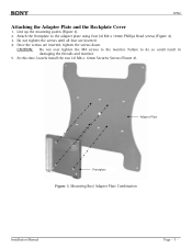
... 3. Failure to the monitor. Attach the frontplate to the adapter plate using four (4) M4 x 10mm Phillips Head screws (Figure 4). 3. Mounting Box/ Adapter Plate Combination Installation Manual Page - 7 - Do not tighten the screws until all four are inserted, tighten the screws down. Line up the mounting points (Figure 3). 2. At this time, loosely...
... 3. Failure to the monitor. Attach the frontplate to the adapter plate using four (4) M4 x 10mm Phillips Head screws (Figure 4). 3. Mounting Box/ Adapter Plate Combination Installation Manual Page - 7 - Do not tighten the screws until all four are inserted, tighten the screws down. Line up the mounting points (Figure 3). 2. At this time, loosely...
Mounting Bracket Instruction Manual
Page 10
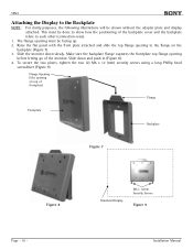
... must be done to show how the positioning of frontplate) Flange Frontplate Backplate Figure 7 Figure 8 Page - 10 - Simulated Display M6 x 12mm Security Screws Figure 9 Installation Manual Slide down slowly. To secure the two plates, tighten the two (2) M6 x 12 (mm) security screws using a long Phillip head screwdriver (Figure 9). This must be...
... must be done to show how the positioning of frontplate) Flange Frontplate Backplate Figure 7 Figure 8 Page - 10 - Simulated Display M6 x 12mm Security Screws Figure 9 Installation Manual Slide down slowly. To secure the two plates, tighten the two (2) M6 x 12 (mm) security screws using a long Phillip head screwdriver (Figure 9). This must be...
Mounting Bracket Instruction Manual
Page 12
.... 16540 West Bernardo Drive San Diego, CA 92127 (800) 350-3477 www.sony.com Installation Manual Customer Support In the event of missing and/or damaged equipment, or technical questions, the following information can help in materials and ...workmanship. SFM2 Warranty Limited Lifetime Warranty This product carries a limited lifetime warranty from ship date against defects in the completion of the installation. Sony Electronics...
.... 16540 West Bernardo Drive San Diego, CA 92127 (800) 350-3477 www.sony.com Installation Manual Customer Support In the event of missing and/or damaged equipment, or technical questions, the following information can help in materials and ...workmanship. SFM2 Warranty Limited Lifetime Warranty This product carries a limited lifetime warranty from ship date against defects in the completion of the installation. Sony Electronics...

Operating Instructions (Flat Panel Display)
Page 2
... frequency energy and, if not installed and used in accordance with Part 15 of Conformity Trade Name: SONY Model: FWD-42LX1/42LX1E/32LX1/ 32LX1E Responsible Party: Sony Electronics Inc. Telephone Number: 858-942-2230 This device complies with the instructions, may call upon your...or an experienced radio/TV technician for a Class B digital device, pursuant to provide reasonable protection against harmful interference in this manual could void your Sony dealer regarding this equipment. If you carry the display unit, hold the unit itself, not the speakers. For customers in...
... frequency energy and, if not installed and used in accordance with Part 15 of Conformity Trade Name: SONY Model: FWD-42LX1/42LX1E/32LX1/ 32LX1E Responsible Party: Sony Electronics Inc. Telephone Number: 858-942-2230 This device complies with the instructions, may call upon your...or an experienced radio/TV technician for a Class B digital device, pursuant to provide reasonable protection against harmful interference in this manual could void your Sony dealer regarding this equipment. If you carry the display unit, hold the unit itself, not the speakers. For customers in...
Operating Instructions (Flat Panel Display)
Page 14
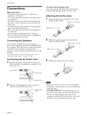
Please be in the illustrations. • You are cautioned that the ferrite core does not slide. For details on connecting the speakers, see the operating manual that will not be sure to connect the speakers correctly. Within 10 mm (13/32 inch) Within 10 mm (13/32 inch) 2 Wind the stopper ... AC plug holder over the cord until it connects to the AC IN socket cover. Never pull the cable itself. • Refer to the instruction manual of the equipment to be connected. • Insert the plug securely into the AC IN socket. AC IN socket AC power cord To remove the...
Please be in the illustrations. • You are cautioned that the ferrite core does not slide. For details on connecting the speakers, see the operating manual that will not be sure to connect the speakers correctly. Within 10 mm (13/32 inch) Within 10 mm (13/32 inch) 2 Wind the stopper ... AC plug holder over the cord until it connects to the AC IN socket cover. Never pull the cable itself. • Refer to the instruction manual of the equipment to be connected. • Insert the plug securely into the AC IN socket. AC IN socket AC power cord To remove the...

Operating Instructions (Flat Panel Display)
Page 30
..."Dot Phase," "Total H Pixel," "H Size," "H Shift," "V Size," or "V Shift" on the Adjust Screen menu. In such cases, adjust the dot phase manually. All the items of the picture separately. SCREEN CONTROL Adjust Screen Auto Adjust Dot Phase: Total H Pixel: H Size: H Shift: V Size: V Shift: 28..." with M/m and press ENTER. Resizing and Positioning the Picture Resizing and Positioning the Picture You can adjust the screen either automatically or manually. Adjusting the Size, Position, or the Pixels of the Picture Press MENU to fit the screen, or adjust the vertical and horizontal ...
..."Dot Phase," "Total H Pixel," "H Size," "H Shift," "V Size," or "V Shift" on the Adjust Screen menu. In such cases, adjust the dot phase manually. All the items of the picture separately. SCREEN CONTROL Adjust Screen Auto Adjust Dot Phase: Total H Pixel: H Size: H Shift: V Size: V Shift: 28..." with M/m and press ENTER. Resizing and Positioning the Picture Resizing and Positioning the Picture You can adjust the screen either automatically or manually. Adjusting the Size, Position, or the Pixels of the Picture Press MENU to fit the screen, or adjust the vertical and horizontal ...

Protocol Manual
Page 1
FLAT WIDE DISPLAY FWD-42LX1 FWD-32LX1 PROTOCOL MANUAL 1st Edition
FLAT WIDE DISPLAY FWD-42LX1 FWD-32LX1 PROTOCOL MANUAL 1st Edition
