User Manual (XCES_Series_User_Guide)
Page 2
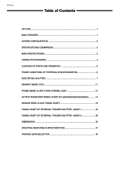
... OF PARTS AND OPERATION 5 PHASE CONDITIONS OF EXTERNAL SYNCHRONIZATION 6 ELECTRONIC SHUTTER 7 RESTART RESET (R.R 11 FRAME IMAGE OUTPUT WITH STROBE LIGHT 13 OUTPUT WAVEFORM TIMING CHART (XC-ES50/EI50/ES30/EI30(EIA 14 SENSOR READ CLOCK TIMING CHART 18 TIMING CHART OF EXTERNAL TRIGGER SHUTTER - MODE 1 22 TIMING CHART OF EXTERNAL TRIGGER SHUTTER -
... OF PARTS AND OPERATION 5 PHASE CONDITIONS OF EXTERNAL SYNCHRONIZATION 6 ELECTRONIC SHUTTER 7 RESTART RESET (R.R 11 FRAME IMAGE OUTPUT WITH STROBE LIGHT 13 OUTPUT WAVEFORM TIMING CHART (XC-ES50/EI50/ES30/EI30(EIA 14 SENSOR READ CLOCK TIMING CHART 18 TIMING CHART OF EXTERNAL TRIGGER SHUTTER - MODE 1 22 TIMING CHART OF EXTERNAL TRIGGER SHUTTER -

User Manual (XCES_Series_User_Guide)
Page 3
... of each mode on rear panel The setting of the XC-ES30/30CE, XC-ES50/50CE, XC-EI30/30CE, and XC-EI50/50CE can be used in low-intensity illumination. OUTLINE XC-E series The XC-ES30/30CE, XC-ES50/50CE, XC-EI30/30CE, and XC-EI50/50CE are located on the rear panel. or 1/2-inch IT...the external system. This function is used for long exposures and strobe with the existing devices, the XCES30/30CE, XC-ES50/50CE, XC-EI30/30CE, and XC-EI50/50CE incorporate significant shock and vibration resistance to capture a clear image even in industrial applications implements compact size and ...
... of each mode on rear panel The setting of the XC-ES30/30CE, XC-ES50/50CE, XC-EI30/30CE, and XC-EI50/50CE can be used in low-intensity illumination. OUTLINE XC-E series The XC-ES30/30CE, XC-ES50/50CE, XC-EI30/30CE, and XC-EI50/50CE are located on the rear panel. or 1/2-inch IT...the external system. This function is used for long exposures and strobe with the existing devices, the XCES30/30CE, XC-ES50/50CE, XC-EI30/30CE, and XC-EI50/50CE incorporate significant shock and vibration resistance to capture a clear image even in industrial applications implements compact size and ...
User Manual (XCES_Series_User_Guide)
Page 4
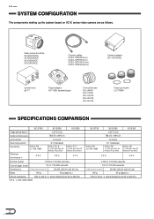
Video camera module XC-ES50/50CE XC-ES30/30CE XC-EI50/50CE XC-EI30/30CE Camera cables CCXC-12P02N (2 m) CCXC-12P05N (5 m) CCXC-12P10N (10 m) CCXC-12P25N (25 m) Camera adaptor DC-700/700CE Junction box JB-77 Tripod adaptor ...-08YM VCL-12YM VCL-16Y-M VCL-25Y-M VCL-50Y-M Close-up the system based on XC-E series video camera are as follows. XC-E series SYSTEM CONFIGURATION The components making up ring kit LO-77ERK SPECIFICATIONS COMPARISON XC-ST50 XC-ES50 XC-EI50 Image pickup device 1/2"IT CCD Number of effective pixels Lens mount 768 (H) x494 (V) C mount Scanning...
Video camera module XC-ES50/50CE XC-ES30/30CE XC-EI50/50CE XC-EI30/30CE Camera cables CCXC-12P02N (2 m) CCXC-12P05N (5 m) CCXC-12P10N (10 m) CCXC-12P25N (25 m) Camera adaptor DC-700/700CE Junction box JB-77 Tripod adaptor ...-08YM VCL-12YM VCL-16Y-M VCL-25Y-M VCL-50Y-M Close-up the system based on XC-E series video camera are as follows. XC-E series SYSTEM CONFIGURATION The components making up ring kit LO-77ERK SPECIFICATIONS COMPARISON XC-ST50 XC-ES50 XC-EI50 Image pickup device 1/2"IT CCD Number of effective pixels Lens mount 768 (H) x494 (V) C mount Scanning...

User Manual (XCES_Series_User_Guide)
Page 5
... device XC-ES50/50CE, XC-EI50/50CE: 1/2-inch interline transfer CCD XC-ES30/30CE, XC-EI30/30CE: 1/3-inch interline transfer CCD Number of effective pixels XC-ES50/EI50, XC-ES30/EI30: 768 (H)x494 (V) XC-ES50CE/EI50CE, XC-ES30CE/EI30CE: 752 (H)x582 (V) CCD horizontal driving frequency XC-ES50/EI50, XC-ES30/EI30: 14.318 MHz XC-ES50CE/EI50CE, XC-ES30CE/EI30CE: 14.187 MHz CCD vertical driving frequency XC-ES50/EI50, XC-ES30...
... device XC-ES50/50CE, XC-EI50/50CE: 1/2-inch interline transfer CCD XC-ES30/30CE, XC-EI30/30CE: 1/3-inch interline transfer CCD Number of effective pixels XC-ES50/EI50, XC-ES30/EI30: 768 (H)x494 (V) XC-ES50CE/EI50CE, XC-ES30CE/EI30CE: 752 (H)x582 (V) CCD horizontal driving frequency XC-ES50/EI50, XC-ES30/EI30: 14.318 MHz XC-ES50CE/EI50CE, XC-ES30CE/EI30CE: 14.187 MHz CCD vertical driving frequency XC-ES50/EI50, XC-ES30...

User Manual (XCES_Series_User_Guide)
Page 6
...215; × × : Can be used. ×: Cannot be used . CONNECTION DIAGRAM C-mount lens VCL-08Y-M VCL-12Y-M XC-ES50/50CE XC-ES30/30CE XC-EI50/50CE XC-EI30/30CE VCL-16Y-M VCL-25Y-M Tripod adaptor VCT-333I LO-77ERK VCL-50Y-M Close-up ring kit Camera cable CCXC-12P02N CCXC... input terminal is provided.) DC +12 V VIDEO OUT HD/VD Note : All functions of the XC-ES50/50CE, XC-ES30/30CE, XC-EI50/50CE, XC-EI30/30CE cannot be selected. Conforms to the table shown below. XC-E series MAIN SPECIFICATIONS Shock resistance 70G Outside dimensions 29 (W) x 29 (H) x 32 (D) mm Weight...
...215; × × : Can be used. ×: Cannot be used . CONNECTION DIAGRAM C-mount lens VCL-08Y-M VCL-12Y-M XC-ES50/50CE XC-ES30/30CE XC-EI50/50CE XC-EI30/30CE VCL-16Y-M VCL-25Y-M Tripod adaptor VCT-333I LO-77ERK VCL-50Y-M Close-up ring kit Camera cable CCXC-12P02N CCXC... input terminal is provided.) DC +12 V VIDEO OUT HD/VD Note : All functions of the XC-ES50/50CE, XC-ES30/30CE, XC-EI50/50CE, XC-EI30/30CE cannot be selected. Conforms to the table shown below. XC-E series MAIN SPECIFICATIONS Shock resistance 70G Outside dimensions 29 (W) x 29 (H) x 32 (D) mm Weight...

User Manual (XCES_Series_User_Guide)
Page 7
...• Factory-setting mode of CCD characteristics). 5 XC-EI30/30CE 2 4 1 23 3 4 7 1 Lens mount section (C mount) A commercial C-mount lens as well as a Sony standard lens can be used . *2: A WEN ... with high precision related to the mechanical center. Switch 9: Selects γ correction on /off . XC-ES30/30CE XC-EI50/50CE . OFF Switch 0: Selects the gain. 8 Volume control switch Manual Mechanical center 7 Shutter speed... Pin No. LOCATION OF PARTS AND OPERATION XC-E series XC-ES50/50CE . OFF Switch 5: Selects the frame or field integration. Switch 5: Selects the frame ...
...• Factory-setting mode of CCD characteristics). 5 XC-EI30/30CE 2 4 1 23 3 4 7 1 Lens mount section (C mount) A commercial C-mount lens as well as a Sony standard lens can be used . *2: A WEN ... with high precision related to the mechanical center. Switch 9: Selects γ correction on /off . XC-ES30/30CE XC-EI50/50CE . OFF Switch 0: Selects the gain. 8 Volume control switch Manual Mechanical center 7 Shutter speed... Pin No. LOCATION OF PARTS AND OPERATION XC-E series XC-ES50/50CE . OFF Switch 5: Selects the frame or field integration. Switch 5: Selects the frame ...
User Manual (XCES_Series_User_Guide)
Page 8
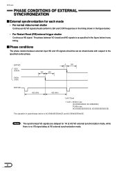
...EVEN) EVEN (ODD) 100 200 5 200 EXT-HD 455 (454) 455 (454) Unit: Clock 1 CLK = 69.84 n sec (XC-ES50/ES30, XC-EI50/EI30) 70.48 n sec (XC-ES50CE/ES30CE, XC-EI50CE/EI30CE) The operation in the figure below in any timing. Note : The synchronized VD signals are delayed for each mode •...signal (should be set as specified in the figure below .) • For Restart Reset (RR)/external trigger shutter Continuous HD signal. XC-E series PHASE CONDITIONS OF EXTERNAL SYNCHRONIZATION External synchronization for 1H at HD/VD external synchronization mode, while there is as shown below with ...
...EVEN) EVEN (ODD) 100 200 5 200 EXT-HD 455 (454) 455 (454) Unit: Clock 1 CLK = 69.84 n sec (XC-ES50/ES30, XC-EI50/EI30) 70.48 n sec (XC-ES50CE/ES30CE, XC-EI50CE/EI30CE) The operation in the figure below in any timing. Note : The synchronized VD signals are delayed for each mode •...signal (should be set as specified in the figure below .) • For Restart Reset (RR)/external trigger shutter Continuous HD signal. XC-E series PHASE CONDITIONS OF EXTERNAL SYNCHRONIZATION External synchronization for 1H at HD/VD external synchronization mode, while there is as shown below with ...

User Manual (XCES_Series_User_Guide)
Page 9
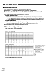
...: 0 / Field: 1 - - - - - - 0 0 0 1/4000 0 1 1 0 1/8000(CCIR) * 1/10000(EIA) Flickerless 1 - 1 - 1 - 0 1 * In the flickerless mode, the normal shutter speed is 1/100 sec for XC-ES50/ES30 and XC-EI50/EI30 (EIA) and 1/120 sec for XC-ES50CE/ES30 CE and XC-EI50CE/EI30CE (CCIR). - - - 1: ON - - - 0: OFF 0 0 0 -: Any Note : It is recommended to set using the DIP switch on the rear...
...: 0 / Field: 1 - - - - - - 0 0 0 1/4000 0 1 1 0 1/8000(CCIR) * 1/10000(EIA) Flickerless 1 - 1 - 1 - 0 1 * In the flickerless mode, the normal shutter speed is 1/100 sec for XC-ES50/ES30 and XC-EI50/EI30 (EIA) and 1/120 sec for XC-ES50CE/ES30 CE and XC-EI50CE/EI30CE (CCIR). - - - 1: ON - - - 0: OFF 0 0 0 -: Any Note : It is recommended to set using the DIP switch on the rear...
User Manual (XCES_Series_User_Guide)
Page 10
...1 0 1 1 0 0 0 1 1 0 0 0 Frame: 0 / Field: 1 0 0 0 0 0 0 1 1 1 - - - - - - 1/4000 0 1 1 0 0 0 1 - - * **1/10000 The external trigger shutter speed is set to 1/10000 sec for XC-ES50/ES30, 6 XC-EI50/EI30 (EIA) and 1/8000 sec for 0 XC-ES50CE/ES30CE, 0 XC-EI50CE/EI30CE (CCIR). 1 1: ON - 0: OFF - -: Any • Using DIP switch on the rear panel to mode 1 or 2. (Refer to the table...internal video signal is set to 1/100 sec for XC-ES50/ES30, 1 XC-EI50/EI30 (EIA) and 1/120 sec for XC-ES50CE/ES30CE, 1 XC-EI50CE/EI30CE (CCIR). 1 0 ** The external ...
...1 0 1 1 0 0 0 1 1 0 0 0 Frame: 0 / Field: 1 0 0 0 0 0 0 1 1 1 - - - - - - 1/4000 0 1 1 0 0 0 1 - - * **1/10000 The external trigger shutter speed is set to 1/10000 sec for XC-ES50/ES30, 6 XC-EI50/EI30 (EIA) and 1/8000 sec for 0 XC-ES50CE/ES30CE, 0 XC-EI50CE/EI30CE (CCIR). 1 1: ON - 0: OFF - -: Any • Using DIP switch on the rear panel to mode 1 or 2. (Refer to the table...internal video signal is set to 1/100 sec for XC-ES50/ES30, 1 XC-EI50/EI30 (EIA) and 1/120 sec for XC-ES50CE/ES30CE, 1 XC-EI50CE/EI30CE (CCIR). 1 0 ** The external ...

User Manual (XCES_Series_User_Guide)
Page 13
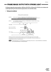
... HD Continuous signal: 15.734 kHz (XC-ES50/ES30, XC-EI50/XC-EI30)Allowable frequency value ±1%, 15.625 kHz (XC-ES50CE/ES30CE, XC-EI50CE/XC-EI30CE) Allowable frequency value ±1% EXT VD VD interval(T): 262.5H or more (XC-ES50/ES30, XC-EI50/XC-EI30) and less than 1 second (Recommended), 312.5H or more (XC-ES50CE/ES30CE, XC-EI50CE/XC-EI30CE) and less than 1 second...
... HD Continuous signal: 15.734 kHz (XC-ES50/ES30, XC-EI50/XC-EI30)Allowable frequency value ±1%, 15.625 kHz (XC-ES50CE/ES30CE, XC-EI50CE/XC-EI30CE) Allowable frequency value ±1% EXT VD VD interval(T): 262.5H or more (XC-ES50/ES30, XC-EI50/XC-EI30) and less than 1 second (Recommended), 312.5H or more (XC-ES50CE/ES30CE, XC-EI50CE/XC-EI30CE) and less than 1 second...
User Manual (XCES_Series_User_Guide)
Page 14
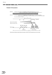
... (XC-ES50/ES30, XC-EI50/XC-EI30) Allowable frequency value ±1%, 15.625 kHz (XC-ES50CE/ES30CE, XC-EI50CE/XC-EI30CE) Allowable frequency value ±1% EXT VD VD interval(T): 262.5H or more (XC-ES50/ES30, XC-EI50/XC-EI30) and less than 1 second (Recommended), 312.5H or more (XC-ES50CE/ES30CE, XC-EI50CE/XC-EI30CE...) and less than 1 second (Recommended) Four or more VD pulses are required. XC-E series RESTART RESET (R.R) Example 2 of ...
... (XC-ES50/ES30, XC-EI50/XC-EI30) Allowable frequency value ±1%, 15.625 kHz (XC-ES50CE/ES30CE, XC-EI50CE/XC-EI30CE) Allowable frequency value ±1% EXT VD VD interval(T): 262.5H or more (XC-ES50/ES30, XC-EI50/XC-EI30) and less than 1 second (Recommended), 312.5H or more (XC-ES50CE/ES30CE, XC-EI50CE/XC-EI30CE...) and less than 1 second (Recommended) Four or more VD pulses are required. XC-E series RESTART RESET (R.R) Example 2 of ...
User Manual (XCES_Series_User_Guide)
Page 15
... overlap. • Timing and conditions EXT HD Continuous signal: 15.734 kHz (XC-ES50/ES30, XC-EI50/XC-EI30)Allowable frequency value ±1%, 15.625 kHz (XC-ES50CE/ES30CE, XC-EI50CE/XC-EI30CE) Allowable frequency value ±1% EXT VD VD : XC-ES50/ES30, XC-EI50/XC-EI30 (1/60sec), XC-ES50CE/ES30CE, XC-EI50CE/XC-EI30CE (1/50sec) Four or more VD pulses are determined by the phase...
... overlap. • Timing and conditions EXT HD Continuous signal: 15.734 kHz (XC-ES50/ES30, XC-EI50/XC-EI30)Allowable frequency value ±1%, 15.625 kHz (XC-ES50CE/ES30CE, XC-EI50CE/XC-EI30CE) Allowable frequency value ±1% EXT VD VD : XC-ES50/ES30, XC-EI50/XC-EI30 (1/60sec), XC-ES50CE/ES30CE, XC-EI50CE/XC-EI30CE (1/50sec) Four or more VD pulses are determined by the phase...
User Manual (XCES_Series_User_Guide)
Page 16
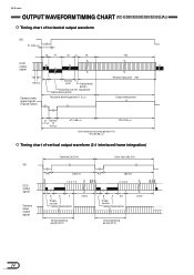
... WAVEFORM TIMING CHART (XC-ES50/EI50/ES30/EI30(EIA)) Timing chart of horizontal output waveform HD 91 (6.36 µs) CCD output signal 40 77 22 3 15 69.8 ns Camera video output ...
... WAVEFORM TIMING CHART (XC-ES50/EI50/ES30/EI30(EIA)) Timing chart of horizontal output waveform HD 91 (6.36 µs) CCD output signal 40 77 22 3 15 69.8 ns Camera video output ...
User Manual (XCES_Series_User_Guide)
Page 17
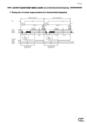
493+494 491+492 489+490 7+8 5+6 3+4 1+2 494 492+493 490+491 488+489 8+9 6+7 4+5 2+3 1 EOLUETCPTURTOWNAICVESFHOURTMTETRIMING CHART (XC-ES50/EI50/ES30/EI30(EIA)) Timing chart of vertical output waveform (2:1 interlaced field integration) VD CCD output signal Camera video output signal Odd field (262.5 H) 9 H 253.5 H Even field (262.5 H) 9 H 253.5 H 18 6 4 Empty transfer Optical black portion 242.5 18 6 3.5 Empty transfer Optical black portion 242.5 Vertical blanking period (20 H) Vertical blanking period (20 H) XC-E series 15
493+494 491+492 489+490 7+8 5+6 3+4 1+2 494 492+493 490+491 488+489 8+9 6+7 4+5 2+3 1 EOLUETCPTURTOWNAICVESFHOURTMTETRIMING CHART (XC-ES50/EI50/ES30/EI30(EIA)) Timing chart of vertical output waveform (2:1 interlaced field integration) VD CCD output signal Camera video output signal Odd field (262.5 H) 9 H 253.5 H Even field (262.5 H) 9 H 253.5 H 18 6 4 Empty transfer Optical black portion 242.5 18 6 3.5 Empty transfer Optical black portion 242.5 Vertical blanking period (20 H) Vertical blanking period (20 H) XC-E series 15
User Manual (XCES_Series_User_Guide)
Page 24
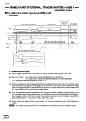
... µs to +10 µs T : T = Under -65 us to +10 µs +10 µs -65 µs Video out 1 2 *5 WEN 250H (XC-ES50/ES30, XC-EI50/EI30) 293H (XC-ES50CE/ES30CE, XC-EI50CE/EI30CE) TRG EXT-VD EXT-VD 65 µs 10 µs Mode transition state External input inhibition area External trigger (50 ms) shutter... goes "low". In this case. *2: Exposure time Te Te = Trigger width + 97 µs (XC-ES50/ES30, XC-EI50/EI30), Te = Trigger width + 120 µs (XC-ES50CE/ES30CE, XC-EI50CE/EI30CE) (The trigger width should be between the falling edge of a trigger pulse and the subsequent ...
... µs to +10 µs T : T = Under -65 us to +10 µs +10 µs -65 µs Video out 1 2 *5 WEN 250H (XC-ES50/ES30, XC-EI50/EI30) 293H (XC-ES50CE/ES30CE, XC-EI50CE/EI30CE) TRG EXT-VD EXT-VD 65 µs 10 µs Mode transition state External input inhibition area External trigger (50 ms) shutter... goes "low". In this case. *2: Exposure time Te Te = Trigger width + 97 µs (XC-ES50/ES30, XC-EI50/EI30), Te = Trigger width + 120 µs (XC-ES50CE/ES30CE, XC-EI50CE/EI30CE) (The trigger width should be between the falling edge of a trigger pulse and the subsequent ...
User Manual (XCES_Series_User_Guide)
Page 25
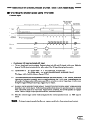
...the HD signal during input operation. *2: Exposure time Te Te = Trigger width + 97 µs (XC-ES50/ES30, XC-EI50/EI30), Te = Trigger width + 120 µs (XC-ES50CE/ES30CE, XC-EI50CE/EI30CE) (The trigger width should be between 2 µs and 1/4 s) *3: The normal operation... Te min 10 µs Video out WEN 1 *5 250H (XC-ES50/ES30, XC-EI50/EI30) 250H (XC-ES50/ES30, XC-EI50/EI30) 293H 293H (XC-ES50CE/ES30CE, (XC-ES50CE/ES30CE, XC-EI50CE/EI30CE) XC-EI50CE/EI30CE) 2 250H (XC-ES50/ES30, XC-EI50/EI30) 293H (XC-ES50CE/ES30CE, XC-EI50CE/EI30CE) • Continuous HD input and single VD input...
...the HD signal during input operation. *2: Exposure time Te Te = Trigger width + 97 µs (XC-ES50/ES30, XC-EI50/EI30), Te = Trigger width + 120 µs (XC-ES50CE/ES30CE, XC-EI50CE/EI30CE) (The trigger width should be between 2 µs and 1/4 s) *3: The normal operation... Te min 10 µs Video out WEN 1 *5 250H (XC-ES50/ES30, XC-EI50/EI30) 250H (XC-ES50/ES30, XC-EI50/EI30) 293H 293H (XC-ES50CE/ES30CE, (XC-ES50CE/ES30CE, XC-EI50CE/EI30CE) XC-EI50CE/EI30CE) 2 250H (XC-ES50/ES30, XC-EI50/EI30) 293H (XC-ES50CE/ES30CE, XC-EI50CE/EI30CE) • Continuous HD input and single VD input...
User Manual (XCES_Series_User_Guide)
Page 26
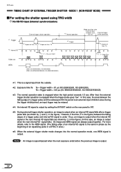
... time Te *5 T : T = Under 10 µs 3 *1: This is a signal input from the outside. *2: Exposure time Te Te = Trigger width + 97 µs (XC-ES50/ES30, XC-EI50/EI30), Te = Trigger width + 120 µs (XC-ES50CE/ES30CE, XC-EI50CE/EI30CE) *3: The normal operation state is engaged when the trigger pulse goes "low". During the trigger inhibit period, an input...
... time Te *5 T : T = Under 10 µs 3 *1: This is a signal input from the outside. *2: Exposure time Te Te = Trigger width + 97 µs (XC-ES50/ES30, XC-EI50/EI30), Te = Trigger width + 120 µs (XC-ES50CE/ES30CE, XC-EI50CE/EI30CE) *3: The normal operation state is engaged when the trigger pulse goes "low". During the trigger inhibit period, an input...
User Manual (XCES_Series_User_Guide)
Page 27
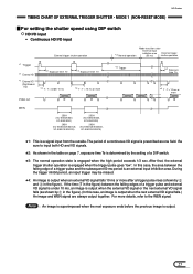
... is under 10 ms, an image is an external input inhibition area. For more 3 WEN 250H (XC-ES50/ES30, XC-EI50/EI30) 293H (XC-ES50CE/ES30CE, XC-EI50CE/EI30CE) 250H (XC-ES50/ES30, XC-EI50/EI30) 293H (XC-ES50CE/ES30CE, XC-EI50CE/EI30CE) *1: This is prescribed as shown by 2 and 3 in the table on page 7, ...*2 Exposure time Te *4 T : T = 10 ms or more details, refer to input both HD and VD signals. *2: As shown in the figure). XC-E series TIMING CHART OF EXTERNAL TRIGGER SHUTTER - The period of a DIP switch. *3: The normal operation state is output when the next external VD signal falls...
... is under 10 ms, an image is an external input inhibition area. For more 3 WEN 250H (XC-ES50/ES30, XC-EI50/EI30) 293H (XC-ES50CE/ES30CE, XC-EI50CE/EI30CE) 250H (XC-ES50/ES30, XC-EI50/EI30) 293H (XC-ES50CE/ES30CE, XC-EI50CE/EI30CE) *1: This is prescribed as shown by 2 and 3 in the table on page 7, ...*2 Exposure time Te *4 T : T = 10 ms or more details, refer to input both HD and VD signals. *2: As shown in the figure). XC-E series TIMING CHART OF EXTERNAL TRIGGER SHUTTER - The period of a DIP switch. *3: The normal operation state is output when the next external VD signal falls...
User Manual (XCES_Series_User_Guide)
Page 28
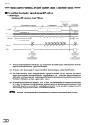
...(50 ms) shutter operation 2 *2 Exposure time Te min. 10 ms Video out WEN 1 250H (XC-ES50/ES30, XC-EI50/EI30) 293H (XC-ES50CE/ES30CE, XC-EI50CE/EI30CE) 2 250H (XC-ES50/ES30, XC-EI50/EI30) 293H (XC-ES50CE/ES30CE, XC-EI50CE/EI30CE) *1: This is a signal input from the rising edge of a trigger pulse (as shown...area between the falling edge of a DIP switch. *3: The normal operation state is engaged several V after a change in the figure). XC-E series TIMING CHART OF EXTERNAL TRIGGER SHUTTER - If the external VD signal is not input under the prescribed conditions, the normal operation is...
...(50 ms) shutter operation 2 *2 Exposure time Te min. 10 ms Video out WEN 1 250H (XC-ES50/ES30, XC-EI50/EI30) 293H (XC-ES50CE/ES30CE, XC-EI50CE/EI30CE) 2 250H (XC-ES50/ES30, XC-EI50/EI30) 293H (XC-ES50CE/ES30CE, XC-EI50CE/EI30CE) *1: This is a signal input from the rising edge of a trigger pulse (as shown...area between the falling edge of a DIP switch. *3: The normal operation state is engaged several V after a change in the figure). XC-E series TIMING CHART OF EXTERNAL TRIGGER SHUTTER - If the external VD signal is not input under the prescribed conditions, the normal operation is...
User Manual (XCES_Series_User_Guide)
Page 29
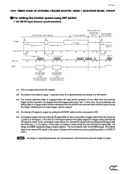
...*5 T : T = Under 10 ms 1 *5 T : T = 10 ms or more 2 WEN 250H (XC-ES50/ES30, XC-EI50/EI30) 293H (XC-ES50CE/ES30CE, XC-EI50CE/EI30CE) 250H (XC-ES50/ES30, XC-EI50/EI30) 293H (XC-ES50CE/ES30CE, XC-EI50CE/EI30CE) *3 Normal operation Mode transition state External input inhibition area External trigger (50 ms) shutter operation 3 ...image is superimposed when the next exposure ends before the previous image is engaged when the high period exceeds 1/3 sec. XC-E series TIMING CHART OF EXTERNAL TRIGGER SHUTTER - After that, the external trigger shutter operation is output when the internal ...
...*5 T : T = Under 10 ms 1 *5 T : T = 10 ms or more 2 WEN 250H (XC-ES50/ES30, XC-EI50/EI30) 293H (XC-ES50CE/ES30CE, XC-EI50CE/EI30CE) 250H (XC-ES50/ES30, XC-EI50/EI30) 293H (XC-ES50CE/ES30CE, XC-EI50CE/EI30CE) *3 Normal operation Mode transition state External input inhibition area External trigger (50 ms) shutter operation 3 ...image is superimposed when the next exposure ends before the previous image is engaged when the high period exceeds 1/3 sec. XC-E series TIMING CHART OF EXTERNAL TRIGGER SHUTTER - After that, the external trigger shutter operation is output when the internal ...

