

Instruction Manual
Page 4
.... To help locate the fault, consult the chapter on "Special Servicing Tools" in the "STIHL Special Tools" manual. Use the part numbers to assembly stand (3) 5910 890 3101. Symbols are included in position. MS 231, MS 231 C, MS 251, MS 251 C 3 Refer to check the part numbers of this manual. chapter 4.2 in this example. 1 3 2 Servicing and repairs are listed...
.... To help locate the fault, consult the chapter on "Special Servicing Tools" in the "STIHL Special Tools" manual. Use the part numbers to assembly stand (3) 5910 890 3101. Symbols are included in position. MS 231, MS 231 C, MS 251, MS 251 C 3 Refer to check the part numbers of this manual. chapter 4.2 in this example. 1 3 2 Servicing and repairs are listed...

Instruction Manual
Page 5
...the aid of repairs or maintenance work, observe all the procedures described in line with the connector, preferably by the STIHL part number, the { logo and the STIHL parts symbol K This symbol may appear alone on the fuel system and the engine. Always wear suitable protective gloves for operations... wear or damage before carrying out repairs or mounting the machine to overheating. 4 MS 231, MS 231 C, MS 251, MS 251 C Avoid damaging the hose barb - Coat the ends of the hoses and the connectors with STIHL press fluid and then push the new hoses on fuel hoses in this service manual...
...the aid of repairs or maintenance work, observe all the procedures described in line with the connector, preferably by the STIHL part number, the { logo and the STIHL parts symbol K This symbol may appear alone on the fuel system and the engine. Always wear suitable protective gloves for operations... wear or damage before carrying out repairs or mounting the machine to overheating. 4 MS 231, MS 231 C, MS 251, MS 251 C Avoid damaging the hose barb - Coat the ends of the hoses and the connectors with STIHL press fluid and then push the new hoses on fuel hoses in this service manual...
Instruction Manual
Page 19
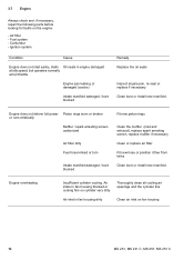
Air filter - Clean bore or install new manifold. 3.7 Engine Always check and, if necessary, repair the following parts before looking for faults on cylinder very dirty Thoroughly clean all cooling air openings and the cylinder fins Air inlet in engine ... Ignition system Condition Cause Engine does not start easily, stalls Oil seals in fan housing dirty Clean air inlet on fan housing 18 MS 231, MS 231 C, MS 251, MS 251 C Carburetor - Engine overheating Insufficient cylinder cooling. Air inlets in fan housing blocked or cooling fins on the engine: - Fuel system -
Air filter - Clean bore or install new manifold. 3.7 Engine Always check and, if necessary, repair the following parts before looking for faults on cylinder very dirty Thoroughly clean all cooling air openings and the cylinder fins Air inlet in engine ... Ignition system Condition Cause Engine does not start easily, stalls Oil seals in fan housing dirty Clean air inlet on fan housing 18 MS 231, MS 231 C, MS 251, MS 251 C Carburetor - Engine overheating Insufficient cylinder cooling. Air inlets in fan housing blocked or cooling fins on the engine: - Fuel system -

Instruction Manual
Page 20
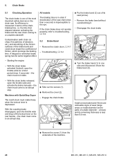
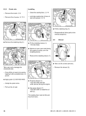
...Unscrew the spark plug. 2310RA001 TG TOP 1 : Apply wrench to hexagon (arrow) and unscrew the clutch (1) - Troubleshooting, b 4.2 - left-hand thread. - MS 231, MS 231 C, MS 251, MS 251 C 19 Remove the shroud, b 6.4 : The locking strip (1) 0000 893 5904 must rest on the piston crown - If it is less than about 80% of... its metal top faces the piston and then push it down firmly - Reassemble all other parts in the illustration....
...Unscrew the spark plug. 2310RA001 TG TOP 1 : Apply wrench to hexagon (arrow) and unscrew the clutch (1) - Troubleshooting, b 4.2 - left-hand thread. - MS 231, MS 231 C, MS 251, MS 251 C 19 Remove the shroud, b 6.4 : The locking strip (1) 0000 893 5904 must rest on the piston crown - If it is less than about 80% of... its metal top faces the piston and then push it down firmly - Reassemble all other parts in the illustration....
Instruction Manual
Page 21
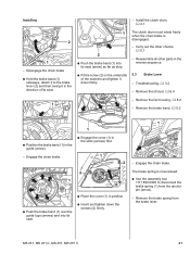
.... 3 seconds) - The clutch drum must not rotate. : Pry the brake band (2) out of the machine. 20 MS 231, MS 231 C, MS 251, MS 251 C the chain must come to troubleshooting, b 3.2. the chain must come areas on inside diameter and/or parts of the lockout lever on the chain saw chain coming to the eye. Its efficiency is...
.... 3 seconds) - The clutch drum must not rotate. : Pry the brake band (2) out of the machine. 20 MS 231, MS 231 C, MS 251, MS 251 C the chain must come to troubleshooting, b 3.2. the chain must come areas on inside diameter and/or parts of the lockout lever on the chain saw chain coming to the eye. Its efficiency is...
Instruction Manual
Page 22
Carry out the other parts in the slots (arrows) first. - Engage the chain brake. Disengage the chain brake : Hold the brake band (1) sideways, attach it to disconnect the brake spring (1) from the brake lever. 2310RA015 TG MS 231, MS 231 C, MS 251, MS 251 C 21 Troubleshooting, b 3.2 - Remove the fan housing, b 8.2 1 - The brake spring is disengaged. 2 : Push the brake...
Carry out the other parts in the slots (arrows) first. - Engage the chain brake. Disengage the chain brake : Hold the brake band (1) sideways, attach it to disconnect the brake spring (1) from the brake lever. 2310RA015 TG MS 231, MS 231 C, MS 251, MS 251 C 21 Troubleshooting, b 3.2 - Remove the fan housing, b 8.2 1 - The brake spring is disengaged. 2 : Push the brake...

Instruction Manual
Page 23
... as far as stop. : Hold the brake lever (2) so that "TOP" faces outwards and the curve (arrow) faces up the holes. 2310RA023 TG 22 MS 231, MS 231 C, MS 251, MS 251 C 1 2 1 1 TOP 2310RA021 TG 2310RA019 TG 2310RA016 TG : Remove the retaining ring (1). 2 1 : Take the brake lever (2) out of the flat... Pull the hand guard (1) and brake lever (2) off the pivot pins (arrows) together. - Check the anchor pin - Clean the pivot pins and disassembled parts, b 14 - Remove the hand guard and brake lever. - Check the cam on the hand guard and replace the hand guard if necessary. 3 2...
... as far as stop. : Hold the brake lever (2) so that "TOP" faces outwards and the curve (arrow) faces up the holes. 2310RA023 TG 22 MS 231, MS 231 C, MS 251, MS 251 C 1 2 1 1 TOP 2310RA021 TG 2310RA019 TG 2310RA016 TG : Remove the retaining ring (1). 2 1 : Take the brake lever (2) out of the flat... Pull the hand guard (1) and brake lever (2) off the pivot pins (arrows) together. - Check the anchor pin - Clean the pivot pins and disassembled parts, b 14 - Remove the hand guard and brake lever. - Check the cam on the hand guard and replace the hand guard if necessary. 3 2...

Instruction Manual
Page 24
... the pivot pins (arrows). : Fit the retaining ring (1). 2 2310RA027 TG TOP 1 : Hook the brake spring (1) to one another in the relaxed condition. Reassemble all other parts in the reverse sequence. 2310RA026 TG : Push the flat spring (1) slightly to the brake lever (arrow). 1 2 2310RA030 TG 1 TOP 2310RA025 TG : Lift the bearing boss... and position them over the pivot pins (arrows). 1 The turns of the hand guard (arrow) slips passed it. If the groove in hand guard, b 14 - MS 231, MS 231 C, MS 251, MS 251 C 23 -
... the pivot pins (arrows). : Fit the retaining ring (1). 2 2310RA027 TG TOP 1 : Hook the brake spring (1) to one another in the relaxed condition. Reassemble all other parts in the reverse sequence. 2310RA026 TG : Push the flat spring (1) slightly to the brake lever (arrow). 1 2 2310RA030 TG 1 TOP 2310RA025 TG : Lift the bearing boss... and position them over the pivot pins (arrows). 1 The turns of the hand guard (arrow) slips passed it. If the groove in hand guard, b 14 - MS 231, MS 231 C, MS 251, MS 251 C 23 -

Instruction Manual
Page 25
...TG 1 : Take the brake lever (2) out of the flat spring (1) into its seat (arrow) as far as stop. 2310RA020 TG 24 MS 231, MS 231 C, MS 251, MS 251 C if it is now relaxed. : Use the assembly tool 1117 890 0900 to disconnect the brake spring (1) from the brake lever. 2310RA032...2310RA018 TG TOP : Push the loop of the hand guard (1). - Check the cam on Machines with QuickStop Super 2 2 - Clean the pivot pins and disassembled parts, b 14 - Lubricate the pivot pins, b 14 1 1 : Disconnect the spring (1) from the brake lever. 2 2310RA034 TG Installing - TOP 2310RA031 TG -...
...TG 1 : Take the brake lever (2) out of the flat spring (1) into its seat (arrow) as far as stop. 2310RA020 TG 24 MS 231, MS 231 C, MS 251, MS 251 C if it is now relaxed. : Use the assembly tool 1117 890 0900 to disconnect the brake spring (1) from the brake lever. 2310RA032...2310RA018 TG TOP : Push the loop of the hand guard (1). - Check the cam on Machines with QuickStop Super 2 2 - Clean the pivot pins and disassembled parts, b 14 - Lubricate the pivot pins, b 14 1 1 : Disconnect the spring (1) from the brake lever. 2 2310RA034 TG Installing - TOP 2310RA031 TG -...

Instruction Manual
Page 27
... b 3.2 TOP 2310RA043 TG : Attach the spring (1) to check free travel must rotate freely. - Troubleshooting, b 3.2 - Reassemble all other parts in the reverse sequence. 1 2310RA028 TG a 0001RA456 TG 5.4.1 Adjusting the brake cable The turns of the brake spring must be tightly against engine... in hand guard, b 14 - If this is released. : Carefully press the lockout lever (1) to the brake lever (arrow). 26 MS 231, MS 231 C, MS 251, MS 251 C 2 1 1 TOP 1 2310RA042 TG 2310RA031 TG 2310RA044 TG TOP : Attach the spring (1) to the brake lever (arrow) so that...
... b 3.2 TOP 2310RA043 TG : Attach the spring (1) to check free travel must rotate freely. - Troubleshooting, b 3.2 - Reassemble all other parts in the reverse sequence. 1 2310RA028 TG a 0001RA456 TG 5.4.1 Adjusting the brake cable The turns of the brake spring must be tightly against engine... in hand guard, b 14 - If this is released. : Carefully press the lockout lever (1) to the brake lever (arrow). 26 MS 231, MS 231 C, MS 251, MS 251 C 2 1 1 TOP 1 2310RA042 TG 2310RA031 TG 2310RA044 TG TOP : Attach the spring (1) to the brake lever (arrow) so that...
Instruction Manual
Page 28
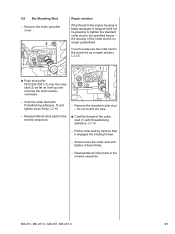
... locate snugly against engine housing (arrows) and the clutch drum must rotate freely. 2 1 - Check the brake cable (1) and retainer (2), replace if necessary MS 231, MS 231 C, MS 251, MS 251 C 27 Reassemble all other parts in that position. Remove the throttle trigger, b 10.3 2310RA053 TG - Turn adjusting screw counter- Remove the carburetor, b 12.5 - Remove the switch lever...
... locate snugly against engine housing (arrows) and the clutch drum must rotate freely. 2 1 - Check the brake cable (1) and retainer (2), replace if necessary MS 231, MS 231 C, MS 251, MS 251 C 27 Reassemble all other parts in that position. Remove the throttle trigger, b 10.3 2310RA053 TG - Turn adjusting screw counter- Remove the carburetor, b 12.5 - Remove the switch lever...

Instruction Manual
Page 30
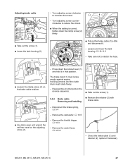
Check position of fuel hose and correct if necessary, b 12.11.2 - Reassemble all other parts in position, b 12.11.2 1 : Turn the spur gear (2) clockwise until the tensioner slide (1) butts against the right-hand end and the screw (3) is ...(3). : Pull out the spur gear (2) and tensioner slide (1). 1 2310RA063 TG : Position the brake cable (1) in the guide (arrow). - Install the throttle trigger, b 10.3 MS 231, MS 231 C, MS 251, MS 251 C 29 Lift the tank housing and secure it into its seat (arrow). : Insert and tighten down the screw (2) firmly. 2310RA059 TG When lifting the...
Check position of fuel hose and correct if necessary, b 12.11.2 - Reassemble all other parts in position, b 12.11.2 1 : Turn the spur gear (2) clockwise until the tensioner slide (1) butts against the right-hand end and the screw (3) is ...(3). : Pull out the spur gear (2) and tensioner slide (1). 1 2310RA063 TG : Position the brake cable (1) in the guide (arrow). - Install the throttle trigger, b 10.3 MS 231, MS 231 C, MS 251, MS 251 C 29 Lift the tank housing and secure it into its seat (arrow). : Insert and tighten down the screw (2) firmly. 2310RA059 TG When lifting the...

Instruction Manual
Page 31
...up with STIHL multipurpose grease, b 14 - If the chain catcher is damaged or worn, install a replacement chain catcher. 2310RA045 TG 5.5.1 Quick Chain Tensioner The quick chain tensioner is an integral part of the sprocket cover. - Check the wing nut (1) and replace if necessary 30 MS 231, MS 231 C, MS 251, MS 251 C ... to the side (arrow) of the wing nut (1) and carefully pry it out of the sprocket cover (1). - Clean all disassembled parts, b 14 - Reassemble in the reverse sequence. - When installing the adjusting wheel, make sure its teeth face the cover plate. -
...up with STIHL multipurpose grease, b 14 - If the chain catcher is damaged or worn, install a replacement chain catcher. 2310RA045 TG 5.5.1 Quick Chain Tensioner The quick chain tensioner is an integral part of the sprocket cover. - Check the wing nut (1) and replace if necessary 30 MS 231, MS 231 C, MS 251, MS 251 C ... to the side (arrow) of the wing nut (1) and carefully pry it out of the sprocket cover (1). - Clean all disassembled parts, b 14 - Reassemble in the reverse sequence. - When installing the adjusting wheel, make sure its teeth face the cover plate. -
Instruction Manual
Page 32
...a case use the collar stud in the engine housing is no longer guaranteed. Coat the collar stud with threadlocking adhesive, b 14 - MS 231, MS 231 C, MS 251, MS 251 C 31 Remove the standard collar stud - Fit the collar stud by hand so that it down firmly, b 14 - the security ...of the collar stud (1) with threadlocking adhesive, fit and tighten down firmly. - Reassemble all other parts in the reverse sequence. : Coat ...
...a case use the collar stud in the engine housing is no longer guaranteed. Coat the collar stud with threadlocking adhesive, b 14 - MS 231, MS 231 C, MS 251, MS 251 C 31 Remove the standard collar stud - Fit the collar stud by hand so that it down firmly, b 14 - the security ...of the collar stud (1) with threadlocking adhesive, fit and tighten down firmly. - Reassemble all other parts in the reverse sequence. : Coat ...

Instruction Manual
Page 34
... TG 6.2 Leakage Test Defective oil seals and gaskets or cracks in place. 2310RA079 TG a 2710RA164 TG 2310RA073 TG MS 231, MS 231 C, MS 251, MS 251 C 33 Remove the shroud, b 6.4 c 1 1 b - Moreover, the transition from idle speed to part or full throttle is in castings are the usual causes of the prescribed idle speed difficult, if not impossible...
... TG 6.2 Leakage Test Defective oil seals and gaskets or cracks in place. 2310RA079 TG a 2710RA164 TG 2310RA073 TG MS 231, MS 231 C, MS 251, MS 251 C 33 Remove the shroud, b 6.4 c 1 1 b - Moreover, the transition from idle speed to part or full throttle is in castings are the usual causes of the prescribed idle speed difficult, if not impossible...

Instruction Manual
Page 35
... must be replaced, b 6.3. - Remove the flange 1118 850 4200 from the crankshaft during the piston's induction stroke because there is airtight. 34 MS 231, MS 231 C, MS 251, MS 251 C Install the muffler, b 6.1 - Use a blunt tool to the right - 2 2 1 : Line up the flange (1) 1118 850 ...seals are in good condition. pressure test. : Operate the lever (2) until the pressure gauge (4) indicates a vacuum of 0.5 bar. Reassemble all other parts in the reverse sequence. 4 3 1 2 : Connect hose (1) of fault. 2310RA075 TG : Push ring (2) to the left to no internal ...
... must be replaced, b 6.3. - Remove the flange 1118 850 4200 from the crankshaft during the piston's induction stroke because there is airtight. 34 MS 231, MS 231 C, MS 251, MS 251 C Install the muffler, b 6.1 - Use a blunt tool to the right - 2 2 1 : Line up the flange (1) 1118 850 ...seals are in good condition. pressure test. : Operate the lever (2) until the pressure gauge (4) indicates a vacuum of 0.5 bar. Reassemble all other parts in the reverse sequence. 4 3 1 2 : Connect hose (1) of fault. 2310RA075 TG : Push ring (2) to the left to no internal ...

Instruction Manual
Page 36
...sealing lips of new oil seal with grease, b 14 : Fit press sleeve (2) 1122 893 2405 with snap ring for replacement on closed engine. MS 231, MS 231 C, MS 251, MS 251 C 35 Remove the fan housing, b 8.2 - Hard oil seal without snap ring for replacement on opened engine. Clean the sealing face, b 14... - Reassemble all other parts in its open side facing the ball bearing. Use hard oil seal (2) 9639 003 951 without snap ring -...
...sealing lips of new oil seal with grease, b 14 : Fit press sleeve (2) 1122 893 2405 with snap ring for replacement on closed engine. MS 231, MS 231 C, MS 251, MS 251 C 35 Remove the fan housing, b 8.2 - Hard oil seal without snap ring for replacement on opened engine. Clean the sealing face, b 14... - Reassemble all other parts in its open side facing the ball bearing. Use hard oil seal (2) 9639 003 951 without snap ring -...
Instruction Manual
Page 37
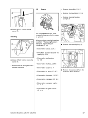
... of new oil seal with the collar (arrow) facing the engine. : Use press sleeve (1) 1122 893 2405 to damage the crankshaft stub. - Reassemble all other parts in its seat by 1 tapping it with a suitable tube or a punch. - Remove the shroud (1). 2310RA086 TG : Apply puller (1) 5910 890 4400. - Remove the clutch, b 4 - Clamp..., over the installing sleeve. 1 2310RA084 TG - 6.3.2 Clutch side Installing - Clean the sealing face, b 14 - The seating face must be flat and free from burrs. 36 MS 231, MS 231 C, MS 251, MS 251 C
... of new oil seal with the collar (arrow) facing the engine. : Use press sleeve (1) 1122 893 2405 to damage the crankshaft stub. - Reassemble all other parts in its seat by 1 tapping it with a suitable tube or a punch. - Remove the shroud (1). 2310RA086 TG : Apply puller (1) 5910 890 4400. - Remove the clutch, b 4 - Clamp..., over the installing sleeve. 1 2310RA084 TG - 6.3.2 Clutch side Installing - Clean the sealing face, b 14 - The seating face must be flat and free from burrs. 36 MS 231, MS 231 C, MS 251, MS 251 C
Instruction Manual
Page 38
... b 4 1 1 2310RA090 TG : Use a drift (2) to drive out the screw (1). Remove the air guide shroud, b 12.4 2310RA092 TG MS 231, MS 231 C, MS 251, MS 251 C 37 Remove the muffler, b 6.1 2 - Remove the shroud, b 6.4 - Remove the oil pump, b 11.3 - Remove the carburetor..., b 12.5 - If the sealing faces are damaged, replace the part concerned, b 3.7. : Remove the retaining ring (1). - Remove the carburetor carrier, b 12.8 -...
... b 4 1 1 2310RA090 TG : Use a drift (2) to drive out the screw (1). Remove the air guide shroud, b 12.4 2310RA092 TG MS 231, MS 231 C, MS 251, MS 251 C 37 Remove the muffler, b 6.1 2 - Remove the shroud, b 6.4 - Remove the oil pump, b 11.3 - Remove the carburetor..., b 12.5 - If the sealing faces are damaged, replace the part concerned, b 3.7. : Remove the retaining ring (1). - Remove the carburetor carrier, b 12.8 -...

Instruction Manual
Page 39
... housing. - the bores in the engine housing, engine pan and cylinder must be in 1 the direction of the clutch and lift it away. 38 MS 231, MS 231 C, MS 251, MS 251 C Loosen and remove the engine pan, remove remaining sealant and clean the sealing faces, b 14 Installing - Remove the engine, b 6.5 Always install new oil seals... the opening (arrow) in the engine housing - Use suitable press sleeves to line up and hold the engine in the engine housing. - Reassemble all other parts in the engine housing - Seal the engine pan with fresh sealant and install, b 6.6, b 14 -
... housing. - the bores in the engine housing, engine pan and cylinder must be in 1 the direction of the clutch and lift it away. 38 MS 231, MS 231 C, MS 251, MS 251 C Loosen and remove the engine pan, remove remaining sealant and clean the sealing faces, b 14 Installing - Remove the engine, b 6.5 Always install new oil seals... the opening (arrow) in the engine housing - Use suitable press sleeves to line up and hold the engine in the engine housing. - Reassemble all other parts in the engine housing - Seal the engine pan with fresh sealant and install, b 6.6, b 14 -


