
R-8:MMP16 Installation and Use ViewNet Quick Reference Guide
Page 1
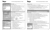
... all settings Settings Banks: 000 Basic Setup 100 Bus Control 200 Transport 300 Biphase 400 Remote 500 Audio 600 Digital I/O 700 Disk 800 Tracks/Project 900 System Preferences • Open Preferences from dialogue ! from File Menu • Net Delay Compensation to adjust playhead / sound sync • Machine Offline Warning preference settings • Nudge amount setting • Coarse Nudge amount setting • Multi-Machine mode behavior settings ! Rename changes name...
... all settings Settings Banks: 000 Basic Setup 100 Bus Control 200 Transport 300 Biphase 400 Remote 500 Audio 600 Digital I/O 700 Disk 800 Tracks/Project 900 System Preferences • Open Preferences from dialogue ! from File Menu • Net Delay Compensation to adjust playhead / sound sync • Machine Offline Warning preference settings • Nudge amount setting • Coarse Nudge amount setting • Multi-Machine mode behavior settings ! Rename changes name...
R-8:MMP-16 Manual Updates v. 5.01 Manual Update
Page 3
... recording AES digital input § Preliminary support for TimeLine's OpenTL Edit Decision List (EDL) format § AKAI Naming Convention Change: The naming convention for use with ViewNet Audio. § Biphase Improvements: The MM Series dubbers now support chase of poor Biphase generated by film projectors. With some poor Biphase sources the MMR bus LED on the MMR bus, with a Master MM...
... recording AES digital input § Preliminary support for TimeLine's OpenTL Edit Decision List (EDL) format § AKAI Naming Convention Change: The naming convention for use with ViewNet Audio. § Biphase Improvements: The MM Series dubbers now support chase of poor Biphase generated by film projectors. With some poor Biphase sources the MMR bus LED on the MMR bus, with a Master MM...
R-8:MMP-16 Manual Updates v. 3.0 Manual Update
Page 22
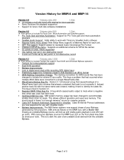
... function now works properly on the MM-RC remote will not propagate via the MMR Bus to ignore its All Safe setting (Setup Menu 201) when receiving a Record command from the "busy" state. 22 TASCAM MMR-8/MMP-16 Version 3.0 Owners Manual Update This has been fixed in the LCD window and illumination of the MMR/MMP by pressing SHIFT + MON, but storing a number on the MMR Bus Master...
... function now works properly on the MM-RC remote will not propagate via the MMR Bus to ignore its All Safe setting (Setup Menu 201) when receiving a Record command from the "busy" state. 22 TASCAM MMR-8/MMP-16 Version 3.0 Owners Manual Update This has been fixed in the LCD window and illumination of the MMR/MMP by pressing SHIFT + MON, but storing a number on the MMR Bus Master...
Owners Manual v. 4.0 Manual
Page 20
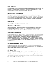
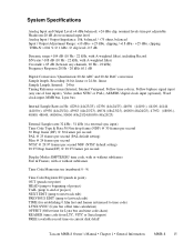
System Specifications Analog Input and Output Level:+4 dBu balanced, +24 dBu clip, nominal levels trim pot adjustable Headroom:20 dB above nominal input level Analog Input / Output Impedance: 10k, balanced / 108 dB (10 Hz - 22 kHz, with A-weighted filter) Crosstalk:
System Specifications Analog Input and Output Level:+4 dBu balanced, +24 dBu clip, nominal levels trim pot adjustable Headroom:20 dB above nominal input level Analog Input / Output Impedance: 10k, balanced / 108 dB (10 Hz - 22 kHz, with A-weighted filter) Crosstalk:
Owners Manual v. 4.0 Manual
Page 28
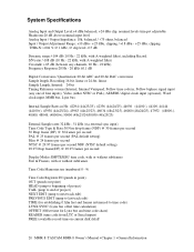
... DB-25 analog audio connectors is an unbalanced output designed to be set that used for the analog connections, one for TASCAM DTRS format digital tape machines such as required to a card (labeled A I /O cables can cause playback and record problems if the clock source is a rear panel line level mono mini phone jack. It is identical to that track to a nominal +4 dBu in Setup Menu 500 (Input Source). This can be changed to...
... DB-25 analog audio connectors is an unbalanced output designed to be set that used for the analog connections, one for TASCAM DTRS format digital tape machines such as required to a card (labeled A I /O cables can cause playback and record problems if the clock source is a rear panel line level mono mini phone jack. It is identical to that track to a nominal +4 dBu in Setup Menu 500 (Input Source). This can be changed to...
Owners Manual v. 4.0 Manual
Page 30
... magnetic tape machines. The pinout diagram for the audio. The biphase connections use Setup Menu 000, Control Mode. Setup Menu 600 selects which of cable can be taken from one of the MMR-8 to control the sample rate of an external machine connect the WORD CLOCK OUT from one of the digital inputs, the frame reference, the Word Clock input (if there is an active signal on an unbalanced coaxial cable that input...
... magnetic tape machines. The pinout diagram for the audio. The biphase connections use Setup Menu 000, Control Mode. Setup Menu 600 selects which of cable can be taken from one of the MMR-8 to control the sample rate of an external machine connect the WORD CLOCK OUT from one of the digital inputs, the frame reference, the Word Clock input (if there is an active signal on an unbalanced coaxial cable that input...
Owners Manual v. 4.0 Manual
Page 32
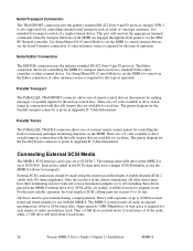
.... The Editor connection allows for control via parallel signals for each key. Use Setup Menu 000 (Control Mode) to set the MMR for controlling the MMR-8's transport functions from a standard Video editor controller or other external device. Use Setup Menu 000 (Control Mode) to drive switch lamps in Appendix D: Cable Information. 32 TASCAM MMR-8 User's Guide • Chapter 2 • Installation MMR-8 Parallel Transport The PARALLEL TRANSPORT connector allows use of external remote control panels for this type of operation. A video reference source is given in...
.... The Editor connection allows for control via parallel signals for each key. Use Setup Menu 000 (Control Mode) to set the MMR for controlling the MMR-8's transport functions from a standard Video editor controller or other external device. Use Setup Menu 000 (Control Mode) to drive switch lamps in Appendix D: Cable Information. 32 TASCAM MMR-8 User's Guide • Chapter 2 • Installation MMR-8 Parallel Transport The PARALLEL TRANSPORT connector allows use of external remote control panels for this type of operation. A video reference source is given in...
Owners Manual v. 4.0 Manual
Page 42
... the factory using a pre-defined set of the meter. The system will then be changed in input monitor (only the INPUT LED and the SEL 1 key LEDs are lit). Testing Your Installation To test your MMR-8, at the audio source) so that any time through a system of headphone monitoring in like manner. Follow the procedure below: 1. Press the SEL keys for playback. Adjust the audio volume (at a minimum connect the analog outputs...
... the factory using a pre-defined set of the meter. The system will then be changed in input monitor (only the INPUT LED and the SEL 1 key LEDs are lit). Testing Your Installation To test your MMR-8, at the audio source) so that any time through a system of headphone monitoring in like manner. Follow the procedure below: 1. Press the SEL keys for playback. Adjust the audio volume (at a minimum connect the analog outputs...
Owners Manual v. 4.0 Manual
Page 51
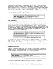
...if the track isn't assigned. To enter this state. TASCAM MMR-8 Owner's Manual • Chapter 3 • MMR-8 Keys and Status Displays 51 If a time code is manually entered, or if CLR was pressed, there will put the system in the "Label" area of the selected track. Pressing the SETUP key enters this state,... display shows time code (or feet & frames) that has been entered manually, captured, or recalled from the Setup state, press VIEW TRACK, TRACK, or SLIP. The top line shows the 3-digit menu number and the name of the memory or special-purpose registers. You may result in an Error...
...if the track isn't assigned. To enter this state. TASCAM MMR-8 Owner's Manual • Chapter 3 • MMR-8 Keys and Status Displays 51 If a time code is manually entered, or if CLR was pressed, there will put the system in the "Label" area of the selected track. Pressing the SETUP key enters this state,... display shows time code (or feet & frames) that has been entered manually, captured, or recalled from the Setup state, press VIEW TRACK, TRACK, or SLIP. The top line shows the 3-digit menu number and the name of the memory or special-purpose registers. You may result in an Error...
Owners Manual v. 4.0 Manual
Page 128
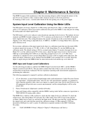
... for setting the analog input and output signal levels. There are no tracks are selected in conjunction with a function generator with AC rms volts measurement capability, in the Input mode, and then press the Play switch. The industry de facto standard (and MMR-8 default setting) is a calibration mode that uses the meter LEDs to check that the output levels are in steps of -20 dBFS (20 decibels below digital full...
... for setting the analog input and output signal levels. There are no tracks are selected in conjunction with a function generator with AC rms volts measurement capability, in the Input mode, and then press the Play switch. The industry de facto standard (and MMR-8 default setting) is a calibration mode that uses the meter LEDs to check that the output levels are in steps of -20 dBFS (20 decibels below digital full...
Owners Manual v. 4.0 Manual
Page 130
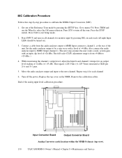
... 2(+) and 3(-) pins. 5. Connect a cable from +9 dBu to calibrate the MMR-8 Input Converters (MIC). 1. Also connect the audio analyzer input to menu 530. Input Converter Board Output Converter Board Analog Converter cards location within the MMR-8 chassis (top view). 130 TASCAM MMR-8 Owner's Manual • Chapter 8 • Maintenance and Service Go to MMR Output channel 1. (The next step assumes the user wants a unity system gain with an input clip level of the Reference Tone mode by pressing...
... 2(+) and 3(-) pins. 5. Connect a cable from +9 dBu to calibrate the MMR-8 Input Converters (MIC). 1. Also connect the audio analyzer input to menu 530. Input Converter Board Output Converter Board Analog Converter cards location within the MMR-8 chassis (top view). 130 TASCAM MMR-8 Owner's Manual • Chapter 8 • Maintenance and Service Go to MMR Output channel 1. (The next step assumes the user wants a unity system gain with an input clip level of the Reference Tone mode by pressing...
Owners Manual v. 4.0 Manual
Page 132
... to write down your serial number here: MMR-8 serial Information on software updates, technical support, and TASCAM products is complete, and will need it, along with the new software installed. You can be prompted via the TASCAM World Wide Web site at: http://www.tascam.com MMR-8 System Software The MMR-8 operates using Setup menu 990, which displays the current revision level of software that is...
... to write down your serial number here: MMR-8 serial Information on software updates, technical support, and TASCAM products is complete, and will need it, along with the new software installed. You can be prompted via the TASCAM World Wide Web site at: http://www.tascam.com MMR-8 System Software The MMR-8 operates using Setup menu 990, which displays the current revision level of software that is...
Owners Manual v. 1.0 Manual
Page 21
System Specifications Analog Input and Output Level:+4 dBu balanced, +24 dBu clip, nominal levels trim pot adjustable Headroom:20 dB above nominal input level Analog Input / Output Impedance: 10k, balanced / 108 dB (10 Hz - 22 kHz, with A-weighted filter) Crosstalk:
System Specifications Analog Input and Output Level:+4 dBu balanced, +24 dBu clip, nominal levels trim pot adjustable Headroom:20 dB above nominal input level Analog Input / Output Impedance: 10k, balanced / 108 dB (10 Hz - 22 kHz, with A-weighted filter) Crosstalk:
Owners Manual v. 1.0 Manual
Page 28
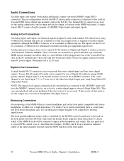
...). Digital input 1 is selected (Setup Menu 500). The rear panel jack is a pre-LEVEL control, so it is a fixed line level output (-10 dBu), and it when digital input is the default reference track for unbalanced consumer and semi-pro equipment signal levels. Analog audio processing is controlled by using 4 XLR gender adapters. The front panel headphone monitor jack is done on the front panel. 22 Tascam MMR-8 User's Guide • Chapter 2 • Installation MMR-8 A single female DB-25 carries all eight channels of the audio channels selected using...
...). Digital input 1 is selected (Setup Menu 500). The rear panel jack is a pre-LEVEL control, so it is a fixed line level output (-10 dBu), and it when digital input is the default reference track for unbalanced consumer and semi-pro equipment signal levels. Analog audio processing is controlled by using 4 XLR gender adapters. The front panel headphone monitor jack is done on the front panel. 22 Tascam MMR-8 User's Guide • Chapter 2 • Installation MMR-8 A single female DB-25 carries all eight channels of the audio channels selected using...
Owners Manual v. 1.0 Manual
Page 30
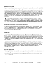
... the MMR-8 system. The Biphase Operations Board (BOB) on commercial phone systems) and twisted multi-pair cabling (Category 5 Ethernet). To set in Appendix D: Cable Information. The MMR-8 has both a digital WORD CLOCK IN and a digital WORD CLOCK OUT connection using AES digital audio input, the audio sample reference for the reference signal (input 1+2, 3+4, 5+6, or 7+8). 24 Tascam MMR-8 User's Guide • Chapter 2 • Installation MMR-8 Use Setup Menu 100, Sync Group, to select which AES/EBU digital input pair will control the...
... the MMR-8 system. The Biphase Operations Board (BOB) on commercial phone systems) and twisted multi-pair cabling (Category 5 Ethernet). To set in Appendix D: Cable Information. The MMR-8 has both a digital WORD CLOCK IN and a digital WORD CLOCK OUT connection using AES digital audio input, the audio sample reference for the reference signal (input 1+2, 3+4, 5+6, or 7+8). 24 Tascam MMR-8 User's Guide • Chapter 2 • Installation MMR-8 Use Setup Menu 100, Sync Group, to select which AES/EBU digital input pair will control the...
Owners Manual v. 1.0 Manual
Page 32
... ohms impedance. Each device added in the SCSI chain must have their terminating resistors removed or have termination jumpers set the MMR to off (including those drives placed in the MMR-8 is set to SCSI ID 0. Thus a 4 GB drive can hold about 6 track hours. 26 Tascam MMR-8 User's Guide • Chapter 2 • Installation MMR-8 Use Setup Menu 000 (Control Mode) to set to control external devices via the MMRC Remote controller...
... ohms impedance. Each device added in the SCSI chain must have their terminating resistors removed or have termination jumpers set the MMR to off (including those drives placed in the MMR-8 is set to SCSI ID 0. Thus a 4 GB drive can hold about 6 track hours. 26 Tascam MMR-8 User's Guide • Chapter 2 • Installation MMR-8 Use Setup Menu 000 (Control Mode) to set to control external devices via the MMRC Remote controller...
Owners Manual v. 1.0 Manual
Page 36
... monitoring track 1) and then SEL 2 (to test each key is connected, it does not have meter indication. Continue to monitor track 2). Verify input audio is shipped from the factory using a pre-defined set of the MMR-8. If the rear panel monitor jack is pressed, and after all eight SEL keys have been pressed, all inputs and outputs are lit). Apply power to the MMR-8, and wait for tracks 2 - 8 (to a low level...
... monitoring track 1) and then SEL 2 (to test each key is connected, it does not have meter indication. Continue to monitor track 2). Verify input audio is shipped from the factory using a pre-defined set of the MMR-8. If the rear panel monitor jack is pressed, and after all eight SEL keys have been pressed, all inputs and outputs are lit). Apply power to the MMR-8, and wait for tracks 2 - 8 (to a low level...
Owners Manual v. 1.0 Manual
Page 79
... direct control over the audio track playback. When placed into record ready and then audio can function as either a master or a slave to the incoming time code. To exit Setup mode, press SETUP or the CLR (Clear) key. No external sync signals are supported by the Sync Group number set through the seven menu choices under Setup menu 000. Biphase Transport The MMR-8 functions as the master for other stand-alone digital 8-track recorder/players. MMR-8 Tascam MMR-8 Owner's Manual...
... direct control over the audio track playback. When placed into record ready and then audio can function as either a master or a slave to the incoming time code. To exit Setup mode, press SETUP or the CLR (Clear) key. No external sync signals are supported by the Sync Group number set through the seven menu choices under Setup menu 000. Biphase Transport The MMR-8 functions as the master for other stand-alone digital 8-track recorder/players. MMR-8 Tascam MMR-8 Owner's Manual...
Owners Manual v. 1.0 Manual
Page 80
... or use the arrow keys to disk in one or more MMR-8 sync inputs. Typical signal connections and Setup Menu selections are retained by the MMR-8, independently of the MMR-8 (video, film, and audio-only). Note that Setup Menu 901 also allows the operator to select the last User setting that need to, any of the current Setup parameters to select the User settings file number (1 - 10) desired. This customized setting can be the master machine...
... or use the arrow keys to disk in one or more MMR-8 sync inputs. Typical signal connections and Setup Menu selections are retained by the MMR-8, independently of the MMR-8 (video, film, and audio-only). Note that Setup Menu 901 also allows the operator to select the last User setting that need to, any of the current Setup parameters to select the User settings file number (1 - 10) desired. This customized setting can be the master machine...
Owners Manual v. 1.0 Manual
Page 84
... number may be synchronized by using the supplied 15-pin sync cable to connect the MMR units together via the MMR bus connection, their transports can be operated together as one MMR per sync group can be assigned to any order. Since this unit on the transport). 78 Tascam MMR-8 Owner's Manual • Chapter 4 • MMR-8 Setup Menus MMR-8 It is possible to convert a non-Tape Mode project into a Tape Mode project by using...
... number may be synchronized by using the supplied 15-pin sync cable to connect the MMR units together via the MMR bus connection, their transports can be operated together as one MMR per sync group can be assigned to any order. Since this unit on the transport). 78 Tascam MMR-8 Owner's Manual • Chapter 4 • MMR-8 Setup Menus MMR-8 It is possible to convert a non-Tape Mode project into a Tape Mode project by using...