
TL-SG3428XFUN V1.6 Installation Guide
Page 3
... how to do the physical connection of client limitations and environmental factors. • This guide uses the specific formats to during the installation. Chapter 4 Configuration This chapter illustrates how to be careful. For local sales information, visit https://www.tp-link.com. • The figures...that should be attended to highlight special messages. To obtain the latest product information, visit the official website: https://www.tp-link.com. Related Document The User Guide and CLI Reference Guide of the product are for demonstration purposes only. This Installation...
... how to do the physical connection of client limitations and environmental factors. • This guide uses the specific formats to during the installation. Chapter 4 Configuration This chapter illustrates how to be careful. For local sales information, visit https://www.tp-link.com. • The figures...that should be attended to highlight special messages. To obtain the latest product information, visit the official website: https://www.tp-link.com. Related Document The User Guide and CLI Reference Guide of the product are for demonstration purposes only. This Installation...
TL-SG3428XFUN V1.6 Installation Guide
Page 4
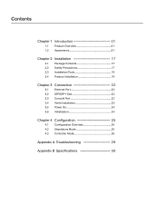
Contents Chapter 1 Introduction 01 1.1 Product Overview 01 1.2 Appearance 01 Chapter 2 Installation 17 2.1 Package Contents 17 2.2 Safety Precautions 17 2.3 Installation Tools 19 2.4 Product Installation 19 Chapter 3 Connection 22 3.1 Ethernet Port 22 3.2 SFP/SFP+ Slot 22 3.3 Console Port 22 3.4 Verify Installation 23 3.5 Power On 24 3.6 Initialization 24 Chapter 4 Configuration----------- 25 4.1 Configuration Overview 25 4.2 Standalone Mode 25 4.3 Controller Mode 26 Appendix A Troubleshooting--------- 29 Appendix B Specifications---------- 30
Contents Chapter 1 Introduction 01 1.1 Product Overview 01 1.2 Appearance 01 Chapter 2 Installation 17 2.1 Package Contents 17 2.2 Safety Precautions 17 2.3 Installation Tools 19 2.4 Product Installation 19 Chapter 3 Connection 22 3.1 Ethernet Port 22 3.2 SFP/SFP+ Slot 22 3.3 Console Port 22 3.4 Verify Installation 23 3.5 Power On 24 3.6 Initialization 24 Chapter 4 Configuration----------- 25 4.1 Configuration Overview 25 4.2 Standalone Mode 25 4.3 Controller Mode 26 Appendix A Troubleshooting--------- 29 Appendix B Specifications---------- 30
TL-SG3428XFUN V1.6 Installation Guide
Page 10
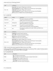
...Gbps, but no activity. Off: No device is powered by PWR1. PWR1 and PWR2 are connected.* The switch is linked to the corresponding port. Green On: Running at 1 Gbps and transmitting or receiving data. For TL-SG3210X-M2 LED PWR SYS Indication On: The switch is abnormal. Flashing: Power supply is...disconnected or it works improperly. PWR2 is powered by PWR2. On or Off: The switch works improperly. 06 Introduction Off: No device is linked to go out after PWR2 is disconnected or it takes priority over PWR2. **When both PWR1 and PWR2 work properly and the switch is ...
...Gbps, but no activity. Off: No device is powered by PWR1. PWR1 and PWR2 are connected.* The switch is linked to the corresponding port. Green On: Running at 1 Gbps and transmitting or receiving data. For TL-SG3210X-M2 LED PWR SYS Indication On: The switch is abnormal. Flashing: Power supply is...disconnected or it works improperly. PWR2 is powered by PWR2. On or Off: The switch works improperly. 06 Introduction Off: No device is linked to go out after PWR2 is disconnected or it takes priority over PWR2. **When both PWR1 and PWR2 work properly and the switch is ...
TL-SG3428XFUN V1.6 Installation Guide
Page 14
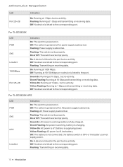
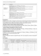
... , battery is charging. JetStream L2/L2+ Managed Switch LED Port 25-28 Indication On: Running at 10/100 Mbps or no device is linked to the port. For TL-SG3428X LED PWR SYS Link/Act 1000Mbps Port 25-28 Indication On: The switch is fully charged. Off: No device is... battery is powered on . Flashing: Transmitting or receiving data. 10 Introduction For TL-SG3428X-UPS LED PWR SYS UPS Link/Act Indication On: The switch is OFF, or the battery cannot supply power. Off: The battery is not connected, the battery switch is powered on . On or Off: The switch works improperly...
... , battery is charging. JetStream L2/L2+ Managed Switch LED Port 25-28 Indication On: Running at 10/100 Mbps or no device is linked to the port. For TL-SG3428X LED PWR SYS Link/Act 1000Mbps Port 25-28 Indication On: The switch is fully charged. Off: No device is... battery is powered on . Flashing: Transmitting or receiving data. 10 Introduction For TL-SG3428X-UPS LED PWR SYS UPS Link/Act Indication On: The switch is OFF, or the battery cannot supply power. Off: The battery is not connected, the battery switch is powered on . On or Off: The switch works improperly...

TL-SG3428XFUN V1.6 Installation Guide
Page 15
... at 10 Gbps and transmitting or receiving data. Green Flashing: Running at 10/100 Mbps or no activity. PWR1 and PWR2 are connected.* The switch is linked to the port but no device is powered by PWR1. Yellow: Not all the fans work properly. Yellow Flashing: Running at 1... Gbps, but no activity. Yellow On: Running at 100 Mbps and transmitting or receiving data. Yellow On: Running at 10 Gbps and transmitting or receiving data. For TL-SG3428XF...
... at 10 Gbps and transmitting or receiving data. Green Flashing: Running at 10/100 Mbps or no activity. PWR1 and PWR2 are connected.* The switch is linked to the port but no device is powered by PWR1. Yellow: Not all the fans work properly. Yellow Flashing: Running at 1... Gbps, but no activity. Yellow On: Running at 100 Mbps and transmitting or receiving data. Yellow On: Running at 10 Gbps and transmitting or receiving data. For TL-SG3428XF...
TL-SG3428XFUN V1.6 Installation Guide
Page 18
...L2+ Managed Switch LED Indication 1000Base-X/ 100Base-FX Green On: Running at 10 Gbps, but no activity. Off: No device is linked to the corresponding port. Note: For TL-SG3452P SFP+ Green On: Running at 1000 Mbps, but no activity. Yellow Flashing: Running at 1 Gbps, but no activity. ...default, the micro-USB connector takes precedence over the RJ45 connector. 100 Mbps/1 Gbps/2.5 Gbps/5 Gbps/10 Gbps RJ45 Port Designed to connect to connect with a bandwidth of 10 Mbps, 100 Mbps or 1000 Mbps. Green Flashing: Running at 1000 Mbps and transmitting or receiving data. Note: ...
...L2+ Managed Switch LED Indication 1000Base-X/ 100Base-FX Green On: Running at 10 Gbps, but no activity. Off: No device is linked to the corresponding port. Note: For TL-SG3452P SFP+ Green On: Running at 1000 Mbps, but no activity. Yellow Flashing: Running at 1 Gbps, but no activity. ...default, the micro-USB connector takes precedence over the RJ45 connector. 100 Mbps/1 Gbps/2.5 Gbps/5 Gbps/10 Gbps RJ45 Port Designed to connect to connect with a bandwidth of 10 Mbps, 100 Mbps or 1000 Mbps. Green Flashing: Running at 1000 Mbps and transmitting or receiving data. Note: ...
TL-SG3428XFUN V1.6 Installation Guide
Page 19
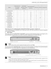
... 10 M/100 M/ 10/100/1000 Mbps 1000 M/2.5 Gbps SFP+ Slot RJ45 Port RJ45 Port SFP Slot Console Port TL-SG3218XP-M2 / TL-SG3428 / TL-SG3428MP / TL-SG3428X / TL-SG3428X-UPS / TL-SG3428XF / TL-SG3428XMP / TL-SG3428X-M2 / TL-SG3428XPP-M2 / TL-SG3452 / TL-SG3452P / TL-SG3452X / TL-SG3452XP / 16 / 2 / 2 / 24 / 4 2 / 24 / 4 2 / 24 4 / 2 / 24 4 / 2 / 4** 4 24 2 / 24 4 / 2 24 / 4 ...rear panel of TL-SG3428X-UPS is shown as the following figure. Your switch may differ in appearance from the depicted. You can connect an external 12...
... 10 M/100 M/ 10/100/1000 Mbps 1000 M/2.5 Gbps SFP+ Slot RJ45 Port RJ45 Port SFP Slot Console Port TL-SG3218XP-M2 / TL-SG3428 / TL-SG3428MP / TL-SG3428X / TL-SG3428X-UPS / TL-SG3428XF / TL-SG3428XMP / TL-SG3428X-M2 / TL-SG3428XPP-M2 / TL-SG3452 / TL-SG3452P / TL-SG3452X / TL-SG3452XP / 16 / 2 / 2 / 24 / 4 2 / 24 / 4 2 / 24 4 / 2 / 24 4 / 2 / 4** 4 24 2 / 24 4 / 2 24 / 4 ...rear panel of TL-SG3428X-UPS is shown as the following figure. Your switch may differ in appearance from the depicted. You can connect an external 12...

TL-SG3428XFUN V1.6 Installation Guide
Page 20
Your switch may differ in appearance from being stolen. Power Socket Connect the female connector of the input voltage (100-240 V~ 50/60 Hz). Make sure that the voltage of the power supply meets the requirement of ... lock (not provided) into the security slot to the Lightning Protection Guide from the Related Documents: https://www.tp-link.com/us/configuration-guides/lightning_protection_guide/. For detailed lightning protection measures, go to https://www.tp-link.com/support, search the model number of your switch and go to the product Support web page, refer...
Your switch may differ in appearance from being stolen. Power Socket Connect the female connector of the input voltage (100-240 V~ 50/60 Hz). Make sure that the voltage of the power supply meets the requirement of ... lock (not provided) into the security slot to the Lightning Protection Guide from the Related Documents: https://www.tp-link.com/us/configuration-guides/lightning_protection_guide/. For detailed lightning protection measures, go to https://www.tp-link.com/support, search the model number of your switch and go to the product Support web page, refer...
TL-SG3428XFUN V1.6 Installation Guide
Page 26
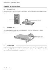
... RJ45 Port RJ45 Port RJ45 Cable 3.2 SFP/SFP+ Slot The following figure demonstrates the connection of the switch to the computer by RJ45 cable as the following figure shows. Figure 3-2 Inserting the SFP/SFP+ Module SFP/SFP+ Slot SFP/SFP+ ... CLI (Command Line Interface) enables you to manage the switch, thus you can load the CLI after connecting the PCs or Terminals to an SFP/SFP+ module. JetStream L2/L2+ Managed Switch Chapter 3 Connection 3.1 Ethernet Port Connect an Ethernet port of SFP/SFP+ slot to the console port on the switch via a cable...
... RJ45 Port RJ45 Port RJ45 Cable 3.2 SFP/SFP+ Slot The following figure demonstrates the connection of the switch to the computer by RJ45 cable as the following figure shows. Figure 3-2 Inserting the SFP/SFP+ Module SFP/SFP+ Slot SFP/SFP+ ... CLI (Command Line Interface) enables you to manage the switch, thus you can load the CLI after connecting the PCs or Terminals to an SFP/SFP+ module. JetStream L2/L2+ Managed Switch Chapter 3 Connection 3.1 Ethernet Port Connect an Ethernet port of SFP/SFP+ slot to the console port on the switch via a cable...
TL-SG3428XFUN V1.6 Installation Guide
Page 27
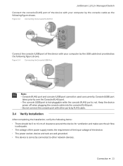
...socket, device and rack are well grounded. ■ The device is not. Figure 3-3 Connecting the Console (RJ45) Port Connect the console (USB) port of the device with other network devices. Connection 23 Keep the device power off when plugging the console cable into the console (RJ45) port...priority over the Console (RJ45) port. ■ The console (USB) port is hot-pluggable while the console (RJ45) port is correctly connected to other ports by RJ45 cable. 3.4 Verify Installation After completing the installation, verify the following items: ■ There should be used concurrently...
...socket, device and rack are well grounded. ■ The device is not. Figure 3-3 Connecting the Console (RJ45) Port Connect the console (USB) port of the device with other network devices. Connection 23 Keep the device power off when plugging the console cable into the console (RJ45) port...priority over the Console (RJ45) port. ■ The console (USB) port is hot-pluggable while the console (RJ45) port is correctly connected to other ports by RJ45 cable. 3.4 Verify Installation After completing the installation, verify the following items: ■ There should be used concurrently...
TL-SG3428XFUN V1.6 Installation Guide
Page 28
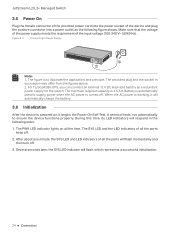
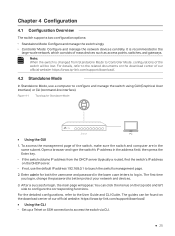
Figure 3-5 Connecting to illustrate the application and principle. The provided plug and the socket in the following figure shows. A series of the input voltage (100‑240 V~ ... a redundant power supply for the switch. After about one minute, the SYS LED and LED indicators of all the ports keep off . For TL-SG3428X-UPS, you can connect an external 12 V DC lead-acid battery as the following order: 1. The minimum required capacity is to Power Supply Note: 1. The PWR LED...
Figure 3-5 Connecting to illustrate the application and principle. The provided plug and the socket in the following figure shows. A series of the input voltage (100‑240 V~ ... a redundant power supply for the switch. After about one minute, the SYS LED and LED indicators of all the ports keep off . For TL-SG3428X-UPS, you can connect an external 12 V DC lead-acid battery as the following order: 1. The minimum required capacity is to Power Supply Note: 1. The PWR LED...
TL-SG3428XFUN V1.6 Installation Guide
Page 29
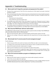
...network, which consists of the switch will appear. The guides can click the menus on the download center of our official website: https://www.tp-link.com/support/download/. 4.2 Standalone Mode In Standalone Mode, use the default IP address 192.168.0.1 to configure the corresponding functions. Enter admin... the switch's IP address in . To access the management page of our official website: https://www.tp-link.com/support/download/. ■ Using the CLI ■ Set up a Telnet or SSH connection to log in the address field, then press the Enter key. ■ If the switch obtains ...
...network, which consists of the switch will appear. The guides can click the menus on the download center of our official website: https://www.tp-link.com/support/download/. 4.2 Standalone Mode In Standalone Mode, use the default IP address 192.168.0.1 to configure the corresponding functions. Enter admin... the switch's IP address in . To access the management page of our official website: https://www.tp-link.com/support/download/. ■ Using the CLI ■ Set up a Telnet or SSH connection to log in the address field, then press the Enter key. ■ If the switch obtains ...

TL-SG3428XFUN V1.6 Installation Guide
Page 31
... function enabled) is also the IP address of your devices according to its web page. 4. If you start, be sure to power up and connect your controller according to the topology figure. • A DHCP server (typically a router with Windows OS or Linux OS, download the Omada Software...your local network. • Omada Controller must have created and click Log in . Make sure that Cloud Access is enabled on your controller. tp-link.com/support/download/omada-software-controller/. In the result list, find the IP address of the router. 2. Enter the username and password you ...
... function enabled) is also the IP address of your devices according to its web page. 4. If you start, be sure to power up and connect your controller according to the topology figure. • A DHCP server (typically a router with Windows OS or Linux OS, download the Omada Software...your local network. • Omada Controller must have created and click Log in . Make sure that Cloud Access is enabled on your controller. tp-link.com/support/download/omada-software-controller/. In the result list, find the IP address of the router. 2. Enter the username and password you ...
TL-SG3428XFUN V1.6 Installation Guide
Page 33
... to delete all the users and passwords. If the PWR/Power LED worked abnormally, take the following : 1. Check if the console cable is properly connected. 2. Enter the number 6 to select the "Password recovery" option and enter Y to factory defaults. Try the following steps: 1. Q4. The ...when the power system works normally. Make sure that the power cable is connected properly, and the power contact is connected properly. 2. Make sure the IP address of the switch? 1. Appendix A Troubleshooting Q1. Connect the console port of your PC is set as None. Power off the...
... to delete all the users and passwords. If the PWR/Power LED worked abnormally, take the following : 1. Check if the console cable is properly connected. 2. Enter the number 6 to select the "Password recovery" option and enter Y to factory defaults. Try the following steps: 1. Q4. The ...when the power system works normally. Make sure that the power cable is connected properly, and the power contact is connected properly. 2. Make sure the IP address of the switch? 1. Appendix A Troubleshooting Q1. Connect the console port of your PC is set as None. Power off the...

TL-SG3428XFUN V1.6 Installation Guide
Page 38
Please read and follow the above safety information when operating the device. We cannot guarantee that no accidents or damage will occur due to improper use in locations where children are likely to be present. This equipment is not suitable for use of the device. Please use this product with earthing connection through the power supply cord or plug. • Plug the product into the wall outlets with care and operate at your own risk.
Please read and follow the above safety information when operating the device. We cannot guarantee that no accidents or damage will occur due to improper use in locations where children are likely to be present. This equipment is not suitable for use of the device. Please use this product with earthing connection through the power supply cord or plug. • Plug the product into the wall outlets with care and operate at your own risk.


