Manual
Page 5
TABLE OF CONTENT About This Guide 1 Purpose 1 Terms/Usage 1 Introduction 3 Fast Ethernet Technology 3 Switching Technology 4 VLAN (Virtual Local Area Network 5 Features 5 Unpacking and Installation 7 Unpacking 7 Installation 7 Rack Mounting 8 Connecting Network Cable 9 AC Power 9 Identifying External Components 11 Front Panel 11 Rear Panel 12 Understanding LED Indicators 13 Power and System LEDs 13 Ports 1~24 Status LEDs 13 Fiber Module LEDs 14 Configuration 15 Installing the Web Management Utility 15 Discovery List 16 i
TABLE OF CONTENT About This Guide 1 Purpose 1 Terms/Usage 1 Introduction 3 Fast Ethernet Technology 3 Switching Technology 4 VLAN (Virtual Local Area Network 5 Features 5 Unpacking and Installation 7 Unpacking 7 Installation 7 Rack Mounting 8 Connecting Network Cable 9 AC Power 9 Identifying External Components 11 Front Panel 11 Rear Panel 12 Understanding LED Indicators 13 Power and System LEDs 13 Ports 1~24 Status LEDs 13 Fiber Module LEDs 14 Configuration 15 Installing the Web Management Utility 15 Discovery List 16 i
Manual
Page 6
Monitor List 17 Device Setting 19 Toolbar 20 Configuring the Switch 21 Login 22 Main Menu 24 Configuring Setup Setting 24 Port Settings 24 VLAN Settings (Virtual Local Area Network 26 Device Status 27 Statistic 27 System Setting 28 Trap Setting 29 Set Password 30 Backup Setting 30 Reset Setting 31 Logout 31 Technical Specifications 33 ii
Monitor List 17 Device Setting 19 Toolbar 20 Configuring the Switch 21 Login 22 Main Menu 24 Configuring Setup Setting 24 Port Settings 24 VLAN Settings (Virtual Local Area Network 26 Device Status 27 Statistic 27 System Setting 28 Trap Setting 29 Set Password 30 Backup Setting 30 Reset Setting 31 Logout 31 Technical Specifications 33 ii
Manual
Page 10
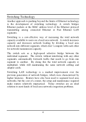
... Ethernet packets at the MAC address level of the Ethernet protocol transmitting among connected Ethernet or Fast Ethernet LAN segments. The switch acts as a high-speed selective bridge between the individual segments. The switch, without interfering with each other segments, automatically forwards traffic that needs to go from one segment to most kinds of local area network congestion problems. 4 Routers have also been used to users on a local area network. Switching...
... Ethernet packets at the MAC address level of the Ethernet protocol transmitting among connected Ethernet or Fast Ethernet LAN segments. The switch acts as a high-speed selective bridge between the individual segments. The switch, without interfering with each other segments, automatically forwards traffic that needs to go from one segment to most kinds of local area network congestion problems. 4 Routers have also been used to users on a local area network. Switching...
Manual
Page 11
... in the Switch. VLAN (Virtual Local Area Network) A VLAN is no need to use cross-over cables or an up-link port u Full/half duplex transfer mode for each port u Wire speed reception and transmission u Store-and-Forward switching scheme capability to support rate adaptation and ensure data integrity u Up to 4K unicast addresses entities per device, self-learning, and table aging u 768KBytes packet buffer u Supports IEEE 802.3x flow control for routers, using VLAN is to...
... in the Switch. VLAN (Virtual Local Area Network) A VLAN is no need to use cross-over cables or an up-link port u Full/half duplex transfer mode for each port u Wire speed reception and transmission u Store-and-Forward switching scheme capability to support rate adaptation and ensure data integrity u Up to 4K unicast addresses entities per device, self-learning, and table aging u 768KBytes packet buffer u Supports IEEE 802.3x flow control for routers, using VLAN is to...
Manual
Page 12
u Supports Back-pressure flow control for half-duplex mode ports u Supports Port-setting for Speed/Disable, Flow control u Supports port-base VLAN u Supports port-base QoS u Optional one port 100BASE-FX Fiber module in the rear panel for length extension u Easy configuration via WEB Browser u Easy setting via Web Management Utility u Standard 19" Rack-mount size 6
u Supports Back-pressure flow control for half-duplex mode ports u Supports Port-setting for Speed/Disable, Flow control u Supports port-base VLAN u Supports port-base QoS u Optional one port 100BASE-FX Fiber module in the rear panel for length extension u Easy configuration via WEB Browser u Easy setting via Web Management Utility u Standard 19" Rack-mount size 6
Manual
Page 13
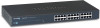
.... See Technical Specifications for the Switch. When installing, consider the following items: u One 24-Port 10/100Mbps Fast Ethernet Web Smart Switch u One AC power cord, suitable for your local reseller for ventilation. 7 Install the Switch in a fairly cool and dry place. Unpacking Open the shipping cartons of the hub for replacement. The carton should contain the following pointers: Install the Switch in a site free from strong...
.... See Technical Specifications for the Switch. When installing, consider the following items: u One 24-Port 10/100Mbps Fast Ethernet Web Smart Switch u One AC power cord, suitable for your local reseller for ventilation. 7 Install the Switch in a fairly cool and dry place. Unpacking Open the shipping cartons of the hub for replacement. The carton should contain the following pointers: Install the Switch in a site free from strong...
Manual
Page 15
... unit adjacent to the local power source automatically and may be turned on without worrying if you are Auto-MDI type port. These ports are using a standard or crossover cable. Connecting Network Cable The Switch supports 10Mbps Ethernet or 100Mbps Fast Ethernet and it runs both in half and full duplex mode. The switch's power supply will adjust to the AC power connector and the system fan. The Switch can auto transform to MDI-II...
... unit adjacent to the local power source automatically and may be turned on without worrying if you are Auto-MDI type port. These ports are using a standard or crossover cable. Connecting Network Cable The Switch supports 10Mbps Ethernet or 100Mbps Fast Ethernet and it runs both in half and full duplex mode. The switch's power supply will adjust to the AC power connector and the system fan. The Switch can auto transform to MDI-II...
Manual
Page 17
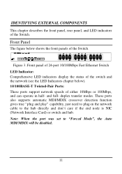
... Ports: These ports support network speeds of either 10Mbps or 100Mbps, and can operate in the network cable to "Forced Mode", the Auto MDI/MDIX will be disabled. 11 Front panel of 24-port 10/100Mbps Fast Ethernet Switch LED Indicator: Comprehensive LED indicators display the status of the switch and the network (see the LED Indicators chapter below shows the front panels of the Switch. duplex transfer modes. Note: When the port was set...
... Ports: These ports support network speeds of either 10Mbps or 100Mbps, and can operate in the network cable to "Forced Mode", the Auto MDI/MDIX will be disabled. 11 Front panel of 24-port 10/100Mbps Fast Ethernet Switch LED Indicator: Comprehensive LED indicators display the status of the switch and the network (see the LED Indicators chapter below shows the front panels of the Switch. duplex transfer modes. Note: When the port was set...

Manual
Page 18
... Fiber Module to plug into a power outlet. Rear Panel Fiber Module Slot Reset Button AC Power Connector Figure 4. Reset: The Reset button is the slot when the users need to connect to the factory default. Rear panel of the provided power cord into this connector, and the male into the slot. Plug in the female connector of the Switch 100Base-FX Fiber Module Slot This is to reset all the setting...
... Fiber Module to plug into a power outlet. Rear Panel Fiber Module Slot Reset Button AC Power Connector Figure 4. Reset: The Reset button is the slot when the users need to connect to the factory default. Rear panel of the provided power cord into this connector, and the male into the slot. Plug in the female connector of the Switch 100Base-FX Fiber Module Slot This is to reset all the setting...
Manual
Page 19
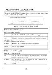
LED indicators of the Switch Power and System LEDs POWER: Power Indicator On : When the Power LED lights on the Ethernet network. : No link. 13 SYSTEM: Management Indicator Blinking : When the CPU is working . Blinking Off : When the Link/ACT LED is blinking, the port is successfully connected to an Ethernet network. UNDERSTANDING LED INDICATORS The front panel LEDs provides instant status feedback, and, helps monitor and troubleshoot when needed. 24-Port 10/100Mbps Ethernet Smart Switch POWER SYSTEM FX 1 2 3 4 Link/ACT FDX 56 78...
LED indicators of the Switch Power and System LEDs POWER: Power Indicator On : When the Power LED lights on the Ethernet network. : No link. 13 SYSTEM: Management Indicator Blinking : When the CPU is working . Blinking Off : When the Link/ACT LED is blinking, the port is successfully connected to an Ethernet network. UNDERSTANDING LED INDICATORS The front panel LEDs provides instant status feedback, and, helps monitor and troubleshoot when needed. 24-Port 10/100Mbps Ethernet Smart Switch POWER SYSTEM FX 1 2 3 4 Link/ACT FDX 56 78...
Manual
Page 20
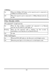
... LED lights on . Fiber Module LEDs FX Link/ACT: Link/Activity On : When the fiber module is in half duplex mode. 14 Off : When the respective port is connected to an Ethernet network, the FX Link/ACT LED lights on , the fiber port is installed and connected to a 10Mbps Ethernet network, or no link. Off : No link. Off : When the green light is off, the fiber port is connected to a 100Mbps Fast Ethernet network. Blinking : When the FX Link/ACT LED is blinking, the fiber module is transmitting or receiving data...
... LED lights on . Fiber Module LEDs FX Link/ACT: Link/Activity On : When the fiber module is in half duplex mode. 14 Off : When the respective port is connected to an Ethernet network, the FX Link/ACT LED lights on , the fiber port is installed and connected to a 10Mbps Ethernet network, or no link. Off : No link. Off : When the green light is off, the fiber port is connected to a 100Mbps Fast Ethernet network. Blinking : When the FX Link/ACT LED is blinking, the fiber module is transmitting or receiving data...

Manual
Page 21
... is located) and click OK. 4. Upon completion, go to install the utility. 5. Installing the Web Management Utility The following gives instructions guiding you can configure the Switch such as VLAN, Port Setting, and System Setting ...etc. With the attached Web Management Utility, you through the installations of the Web Management utility. 1. CONFIGURATION Through the Web Browser you can easily discover all the Web Management Switch, assign the IP Address, changing the password and upgrading the new firmware.
... is located) and click OK. 4. Upon completion, go to install the utility. 5. Installing the Web Management Utility The following gives instructions guiding you can configure the Switch such as VLAN, Port Setting, and System Setting ...etc. With the attached Web Management Utility, you through the installations of the Web Management utility. 1. CONFIGURATION Through the Web Browser you can easily discover all the Web Management Switch, assign the IP Address, changing the password and upgrading the new firmware.

Manual
Page 24
... order to receive Trap information, switch has to monitor. Figure 8. When the "View Trap" button is clicked, a Trap Information window will pop out, it means that you review and click on the event record. There is a light indicator behind the "View Trap" button, when the light indicates in green, it means that happen from the Web Management Switch in the Monitor List. View Trap: The Trap function...
... order to receive Trap information, switch has to monitor. Figure 8. When the "View Trap" button is clicked, a Trap Information window will pop out, it means that you review and click on the event record. There is a light indicator behind the "View Trap" button, when the light indicates in green, it means that happen from the Web Management Switch in the Monitor List. View Trap: The Trap function...
Manual
Page 25
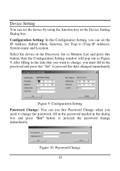
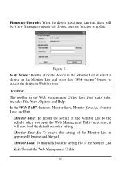
... Monitor List and press this button, then the Configuration Setting window will pop out as Figure 9, after filling in the Device Setting Dialog box. Figure 9. Password Change 19 Device Setting You can set the IP Address, Subnet Mask, Gateway, Set Trap to proceed the password change immediately. you can use this Configuration Setting, you must fill in the dialog box and press "Set" button to (Trap IP Address), System name and Location. Configuration Setting Password Change...
... Monitor List and press this button, then the Configuration Setting window will pop out as Figure 9, after filling in the Device Setting Dialog box. Figure 9. Password Change 19 Device Setting You can set the IP Address, Subnet Mask, Gateway, Set Trap to proceed the password change immediately. you can use this Configuration Setting, you must fill in the dialog box and press "Set" button to (Trap IP Address), System name and Location. Configuration Setting Password Change...
Manual
Page 26
... the setting of the Monitor List in the Web Management Utility have four major tabs, includes File, View, Options and Help. Monitor Load: To manually load the setting file of the Monitor List to the default, when you open the Web Management Utility next time, it will be a new firmware to update the device, use this "Web Access" button to update. Toolbar The toolbar in appointed filename and file path. Monitor Save: To record the setting of the Monitor List...
... the setting of the Monitor List in the Web Management Utility have four major tabs, includes File, View, Options and Help. Monitor Load: To manually load the setting file of the Monitor List to the default, when you open the Web Management Utility next time, it will be a new firmware to update the device, use this "Web Access" button to update. Toolbar The toolbar in appointed filename and file path. Monitor Save: To record the setting of the Monitor List...

Manual
Page 27
... refresh the time of the Web Management Utility and the device. Clear Log: to enable its smart functions including: u Port Setting (Speed, duplex mode, flow control and QoS) u Virtual LAN Group setting (VLAN) u System IP address and password setting u Device status (System status, Port status, Port statistic and VLAN status) 21 In the "View TAB", there are Refresh Time function, this function will show out the version of monitoring. View Log: To show the event of monitoring the device. The Switch can manage, control and monitor the switch from...
... refresh the time of the Web Management Utility and the device. Clear Log: to enable its smart functions including: u Port Setting (Speed, duplex mode, flow control and QoS) u Virtual LAN Group setting (VLAN) u System IP address and password setting u Device status (System status, Port status, Port statistic and VLAN status) 21 In the "View TAB", there are Refresh Time function, this function will show out the version of monitoring. View Log: To show the event of monitoring the device. The Switch can manage, control and monitor the switch from...
Manual
Page 28
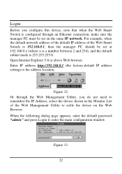
....0.1 (the factory-default IP address setting) to enter the main configuration window. Figure 13. 22 Figure 12. Or through an Ethernet connection, make sure the manager PC must be set on the Web Browser. For example, when the default network address of the default IP address of the Web Management Utility to settle the device on the same IP network. Open Internet Explorer 5.0 or above Web browser. Login Before you configure this device...
....0.1 (the factory-default IP address setting) to enter the main configuration window. Figure 13. 22 Figure 12. Or through an Ethernet connection, make sure the manager PC must be set on the Web Browser. For example, when the default network address of the default IP address of the Web Management Utility to settle the device on the same IP network. Open Internet Explorer 5.0 or above Web browser. Login Before you configure this device...
Manual
Page 32
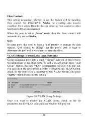
... Enable for avoiding data transfer overflow. there is set to forced mode, then the flow control will automatically set to Disable. To add a VLAN group, press "Add Group" button, the new VLAN configuration window will be handling flow control. Figure 18. VLAN Settings (Virtual Local Area Network) Group individual ports into a small "Virtual" network of the other hardware/software management. Flow Control: This setting determines whether or not the Switch will pop out, you want to modify the VLAN Group, check...
... Enable for avoiding data transfer overflow. there is set to forced mode, then the flow control will automatically set to Disable. To add a VLAN group, press "Add Group" button, the new VLAN configuration window will be handling flow control. Figure 18. VLAN Settings (Virtual Local Area Network) Group individual ports into a small "Virtual" network of the other hardware/software management. Flow Control: This setting determines whether or not the Switch will pop out, you want to modify the VLAN Group, check...

Manual
Page 36
... file. 30 Set Password Password is the invaluable tool for the manager to secure Web Management Switch, use this function to the default setting. etc. To restore a current setting file to the device, you need to backup the setting, press the "Backup" button to save the setting. Abnormal* Receive Error: to restore the setting of the Switch, the current setting includes VLAN, Port Setting ... Once you must specify the backup file and press "Restore" button to send a trap when there are transmit data error...
... file. 30 Set Password Password is the invaluable tool for the manager to secure Web Management Switch, use this function to the default setting. etc. To restore a current setting file to the device, you need to backup the setting, press the "Backup" button to save the setting. Abnormal* Receive Error: to restore the setting of the Switch, the current setting includes VLAN, Port Setting ... Once you must specify the backup file and press "Restore" button to send a trap when there are transmit data error...
Manual
Page 37
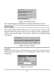
Backup Setting Note: when restoring a recorded file, the current password will not be set to default setting 192.168.0.1. Figure 26. Logout 31 Figure 27. Reset Setting Logout When press this function, the web configuration will be erased. Reset Setting The Factory Reset button helps you to reset the device back to first Login page. Figure 25. Be aware that the entire configuration will be reset, the IP address of the device will go back to the default setting from the factory.
Backup Setting Note: when restoring a recorded file, the current password will not be set to default setting 192.168.0.1. Figure 26. Logout 31 Figure 27. Reset Setting Logout When press this function, the web configuration will be erased. Reset Setting The Factory Reset button helps you to reset the device back to first Login page. Figure 25. Be aware that the entire configuration will be reset, the IP address of the device will go back to the default setting from the factory.


