

Parts List
Page 1
Illustrated Parts Manual Model Number: HTD-2522PF 22" DOUBLE-SIDED HEDGETRIMMER P/N 30216 Rev 000 Date 10-24-07 Nikko Tanaka Engineering U.S.A.,Ltd.• 1028 4th Street SW, Bldg B • Auburn, WA 98001 • Phone: (253) 333-1200 • Fax: (253) 333-1212 www.tanakapowerequipment.com custsvc@nikko-tanaka-usa.com
Illustrated Parts Manual Model Number: HTD-2522PF 22" DOUBLE-SIDED HEDGETRIMMER P/N 30216 Rev 000 Date 10-24-07 Nikko Tanaka Engineering U.S.A.,Ltd.• 1028 4th Street SW, Bldg B • Auburn, WA 98001 • Phone: (253) 333-1200 • Fax: (253) 333-1212 www.tanakapowerequipment.com custsvc@nikko-tanaka-usa.com
Parts List
Page 2
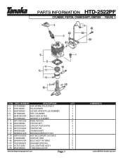
PARTS INFORMATION HTD-2522PF CYLINDER, PISTON, CRANKSHAFT, IGNITION • FIGURE 1 ITEM PART NUMBER DESCRIPTION 1-1 1570168090 CAP,SPARK PLUG ASS'Y 1-2 0181166021 PLUG,SPARK 1-3 2550168020 COVER,SPARK PLUG,RUBBER 1-6 0010300290 SET,CYLINDER 1-7 99461050184 BOLT,HEX,5X18,S 1-9 0170300220 GASKET,CYLINDER 1-11 04101601200 RING,PISTON 1-12 0300168090 PISTON SET 1-13 03900000201 CIRCLIP,PISTON PIN 1-14 03701700200 PIN,PISTON 1-16 0460300280 CRANKSHAFT 1-17 99962091325 BEARING,NEEDLE,F-910 1-18 06810100200 KEY,WOODRUFF,3X13X4.5 1-40 1780300280 CORD,B,140M...
PARTS INFORMATION HTD-2522PF CYLINDER, PISTON, CRANKSHAFT, IGNITION • FIGURE 1 ITEM PART NUMBER DESCRIPTION 1-1 1570168090 CAP,SPARK PLUG ASS'Y 1-2 0181166021 PLUG,SPARK 1-3 2550168020 COVER,SPARK PLUG,RUBBER 1-6 0010300290 SET,CYLINDER 1-7 99461050184 BOLT,HEX,5X18,S 1-9 0170300220 GASKET,CYLINDER 1-11 04101601200 RING,PISTON 1-12 0300168090 PISTON SET 1-13 03900000201 CIRCLIP,PISTON PIN 1-14 03701700200 PIN,PISTON 1-16 0460300280 CRANKSHAFT 1-17 99962091325 BEARING,NEEDLE,F-910 1-18 06810100200 KEY,WOODRUFF,3X13X4.5 1-40 1780300280 CORD,B,140M...
Parts List
Page 3
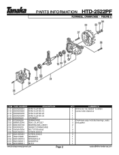
PARTS INFORMATION HTD-2522PF FLYWHEEL, CRANKCASE • FIGURE 2 ITEM PART NUMBER DESCRIPTION 2-19 33000200210 SHIM,12.2X19X.10 2-19 33000200220 SHIM,12.2X19X.15 2-19 33000200230 SHIM,12.2X19X.20 2-19 33000200240 SHIM,12.2X19X.30 2-26 2030300220 GROMMET 2-31 0720300290 CRANKCASE 2-32 99966122240 SEAL,OIL,#12227 2-33 99961600100 BEARING,BALL,#6001 2-34 0900300220 GASKET,CRANKCASE 2-35...
PARTS INFORMATION HTD-2522PF FLYWHEEL, CRANKCASE • FIGURE 2 ITEM PART NUMBER DESCRIPTION 2-19 33000200210 SHIM,12.2X19X.10 2-19 33000200220 SHIM,12.2X19X.15 2-19 33000200230 SHIM,12.2X19X.20 2-19 33000200240 SHIM,12.2X19X.30 2-26 2030300220 GROMMET 2-31 0720300290 CRANKCASE 2-32 99966122240 SEAL,OIL,#12227 2-33 99961600100 BEARING,BALL,#6001 2-34 0900300220 GASKET,CRANKCASE 2-35...

Parts List
Page 5
... VALVE,CHOKE 3-38 99204080030 WASHER,8 3-39 47601700200 BOARD,BLOW OVER CHECK 3-40 99210050012 WASHER,S,5 3-41 99011050602 SCREW,5X60 3-43 4460650020 ELEMENT,CLEANER 3-44 4520650091 COVER,CLEANER,W/BOLT 3-45 3800637C200 BOLT,CLEANER COVER 3-46 4550300290 SET,CARBURETOR 3-50 2230700090 SHIELD,TUBE 3-51 68000731201 CLIP 6.3 3-52 6750404280 FILTER,FUEL 3-53 5910300220 TANK,FUEL 3-54 5950300290 CAP,TANK (BLACK/RED) 3-55 65900801200 COLLAR 3-58 99463050185 BOLT,HEX 5X18PS 3-70 44225143800 PUMP...
... VALVE,CHOKE 3-38 99204080030 WASHER,8 3-39 47601700200 BOARD,BLOW OVER CHECK 3-40 99210050012 WASHER,S,5 3-41 99011050602 SCREW,5X60 3-43 4460650020 ELEMENT,CLEANER 3-44 4520650091 COVER,CLEANER,W/BOLT 3-45 3800637C200 BOLT,CLEANER COVER 3-46 4550300290 SET,CARBURETOR 3-50 2230700090 SHIELD,TUBE 3-51 68000731201 CLIP 6.3 3-52 6750404280 FILTER,FUEL 3-53 5910300220 TANK,FUEL 3-54 5950300290 CAP,TANK (BLACK/RED) 3-55 65900801200 COLLAR 3-58 99463050185 BOLT,HEX 5X18PS 3-70 44225143800 PUMP...
Parts List
Page 6
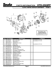
PARTS INFORMATION HTD-2522PF CLUTCH, STARTER, MUFFLER COMPONENTS • FIGURE 4 Recoil Starter Assy Use #762.03002.90 Includes items #11-#19 ITEM PART NUMBER DESCRIPTION 4-3 7210300300 SET,TAIL PIPE,COVER 4-6 7040300290 SET,MUFFLER 4-7 99201060011 WASHER,6 4-8 99053060553 SCREW,HEX.HOLE 4-10 7210300320 PIPE,TAIL 4-11 1120300280 CASE,FAN 4-12 78006097200 SPRING,RECOIL 4-13 77406097200 PULLEY,STARTER 4-15 8390201020 SCREW,SET 4-16 79806500900 PULLEY,STARTER,ASS'Y 4-17 20306000200 GROMMET,PRIMARY CORD 4-18 78306097200 ROPE,STARTER 4-19 78506410200 HANDLE,STARTER 4-20...
PARTS INFORMATION HTD-2522PF CLUTCH, STARTER, MUFFLER COMPONENTS • FIGURE 4 Recoil Starter Assy Use #762.03002.90 Includes items #11-#19 ITEM PART NUMBER DESCRIPTION 4-3 7210300300 SET,TAIL PIPE,COVER 4-6 7040300290 SET,MUFFLER 4-7 99201060011 WASHER,6 4-8 99053060553 SCREW,HEX.HOLE 4-10 7210300320 PIPE,TAIL 4-11 1120300280 CASE,FAN 4-12 78006097200 SPRING,RECOIL 4-13 77406097200 PULLEY,STARTER 4-15 8390201020 SCREW,SET 4-16 79806500900 PULLEY,STARTER,ASS'Y 4-17 20306000200 GROMMET,PRIMARY CORD 4-18 78306097200 ROPE,STARTER 4-19 78506410200 HANDLE,STARTER 4-20...
Parts List
Page 7
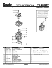
... 5-21 47625004200 COVER,DIAPHRAGM 5-22 54825101200 SCREW,SET www.tanakapowerequipment.com Page 6 QTY COMMENTS 1 Carburetor set includes gasket 2 1 Carburetor Repair Kit - 650-25140-900 1 Gasket / Diaphragm Kit - 652-25140-900 1 1 ~ Contained in Carb Kits 1 1 1 1 1 1 1 4 custsvc@nikko-tanaka-usa.com PARTS INFORMATION HTD-2522PF CARBURETOR • FIGURE 5 A small retainer (560-0217020), has been added to this model after serial # A099801 to prevent the barrel end of the throttle wire from coming...
... 5-21 47625004200 COVER,DIAPHRAGM 5-22 54825101200 SCREW,SET www.tanakapowerequipment.com Page 6 QTY COMMENTS 1 Carburetor set includes gasket 2 1 Carburetor Repair Kit - 650-25140-900 1 Gasket / Diaphragm Kit - 652-25140-900 1 1 ~ Contained in Carb Kits 1 1 1 1 1 1 1 4 custsvc@nikko-tanaka-usa.com PARTS INFORMATION HTD-2522PF CARBURETOR • FIGURE 5 A small retainer (560-0217020), has been added to this model after serial # A099801 to prevent the barrel end of the throttle wire from coming...
Parts List
Page 9
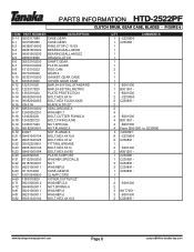
PARTS INFORMATION HTD-2522PF CLUTCH DRUM, GEAR CASE, BLADES • FIGURE 6 ITEM PART NUMBER DESCRIPTION 6-1-1 3003317A80 CASE,GEAR 6-1 3007305080 CASE,GEAR 6-2 99350015002 RING,STOP,C-15 EX 6-3 99961600200 BEARING,BALL,#6002 6-4 99961600202 BEARING,BALL,#6002Z 6-5 2883318080 DRUM,CLUTCH 6-6 30533160200 SHAFT,GEAR 6-7 07533160200 PLATE,GUIDE 6-8 1013316022 ROD,CAM 6-9 3073318020 GEAR,2 6-10 30333160200 GASKET,GEAR CASE 6-11 6303316020 COVER,GEAR CASE 6-12 1223316021 BAR,24-5/8"OAL,STANDARD 6-12 1223317820 BAR,24-5/8"OAL,METRIC 6-13...
PARTS INFORMATION HTD-2522PF CLUTCH DRUM, GEAR CASE, BLADES • FIGURE 6 ITEM PART NUMBER DESCRIPTION 6-1-1 3003317A80 CASE,GEAR 6-1 3007305080 CASE,GEAR 6-2 99350015002 RING,STOP,C-15 EX 6-3 99961600200 BEARING,BALL,#6002 6-4 99961600202 BEARING,BALL,#6002Z 6-5 2883318080 DRUM,CLUTCH 6-6 30533160200 SHAFT,GEAR 6-7 07533160200 PLATE,GUIDE 6-8 1013316022 ROD,CAM 6-9 3073318020 GEAR,2 6-10 30333160200 GASKET,GEAR CASE 6-11 6303316020 COVER,GEAR CASE 6-12 1223316021 BAR,24-5/8"OAL,STANDARD 6-12 1223317820 BAR,24-5/8"OAL,METRIC 6-13...
Parts List
Page 11
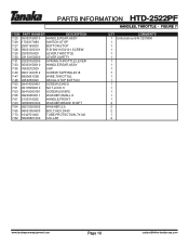
PARTS INFORMATION HTD-2522PF HANDLES, THROTTLE • FIGURE 7 ITEM PART NUMBER DESCRIPTION 7-25 05033150010 HANDLE,REAR,ASSY 7-26 1703317A80 SWITCH,STOP 7-27 2581165020 BUTTON,STOP 7-28 99431030101 R-B 99011030101 SCREW 7-29 2303315020 LEVER,THROTTLE 7-30 23133150200 LEVER,SAFETY 7-31 23233150200 SPRING,THROTTLE LEVER 7-33 05033150010 HANDLE,REAR,ASSY 7-35 7653212020 CAP 7-36 99311041812 SCREW,TAPPING,4X18 7-47 8850651C80 WIRE,THROTTLE 7-48 9253253020 DECAL,STOP BUTTON 7-50 99414050451 SCREW,5X45/S 7-51 99178050010 NUT,LOCK 5 7-53 99415060181 SCREW,6X18PS...
PARTS INFORMATION HTD-2522PF HANDLES, THROTTLE • FIGURE 7 ITEM PART NUMBER DESCRIPTION 7-25 05033150010 HANDLE,REAR,ASSY 7-26 1703317A80 SWITCH,STOP 7-27 2581165020 BUTTON,STOP 7-28 99431030101 R-B 99011030101 SCREW 7-29 2303315020 LEVER,THROTTLE 7-30 23133150200 LEVER,SAFETY 7-31 23233150200 SPRING,THROTTLE LEVER 7-33 05033150010 HANDLE,REAR,ASSY 7-35 7653212020 CAP 7-36 99311041812 SCREW,TAPPING,4X18 7-47 8850651C80 WIRE,THROTTLE 7-48 9253253020 DECAL,STOP BUTTON 7-50 99414050451 SCREW,5X45/S 7-51 99178050010 NUT,LOCK 5 7-53 99415060181 SCREW,6X18PS...
Parts List
Page 12
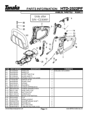
... ~C230891 ITEM PART NUMBER DESCRIPTION 8-1 0513329020 HANDLE,B 8-2 0503329020 HANDLE,A 8-3 2303329020 LEVER,THROTTLE 8-4 2313329020 LEVER,SAFETY 8-5 23233160200 SPRING,THROTTLE LEVER 8-6 1703325380 SWITCH,STOP 8-7 2333329020 LEVER,LOCK 8-8 2453329020 SPRING 8-9 99201040011 WASHER,4 8-10 99341040101 SCREW,TAPPING,4X10 8-11 99072045164 SCREW,TAPPING,4.5X16 8-12 8857311080 WIRE,THROTTLE 8-13 2581165020 BUTTON,STOP 8-14 99011030101 SCREW,3X10 8-16 92533160200 DECAL,STOP BUTTON 8-25 5053319620 CLIP 8-61 2103316022 HANDLE,FRONT 8-63 36832057200 WASHER,BRAKE SHAFT 8-64...
... ~C230891 ITEM PART NUMBER DESCRIPTION 8-1 0513329020 HANDLE,B 8-2 0503329020 HANDLE,A 8-3 2303329020 LEVER,THROTTLE 8-4 2313329020 LEVER,SAFETY 8-5 23233160200 SPRING,THROTTLE LEVER 8-6 1703325380 SWITCH,STOP 8-7 2333329020 LEVER,LOCK 8-8 2453329020 SPRING 8-9 99201040011 WASHER,4 8-10 99341040101 SCREW,TAPPING,4X10 8-11 99072045164 SCREW,TAPPING,4.5X16 8-12 8857311080 WIRE,THROTTLE 8-13 2581165020 BUTTON,STOP 8-14 99011030101 SCREW,3X10 8-16 92533160200 DECAL,STOP BUTTON 8-25 5053319620 CLIP 8-61 2103316022 HANDLE,FRONT 8-63 36832057200 WASHER,BRAKE SHAFT 8-64...
Owner's Manual
Page 2
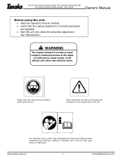
..., HTS-2530PF Owner's Manual Before using this product contains chemicals known to cause cancer, birth defects and other reproductive harm. www.tanaka-usa.com 1 custsvc@tanaka-ism.com Read, understand and follow all warnings and instructions in this manual and on the unit. It is important that the cutting equipment is correctly assembled and adjusted. • Start the unit and check the carburetor adjustment.
..., HTS-2530PF Owner's Manual Before using this product contains chemicals known to cause cancer, birth defects and other reproductive harm. www.tanaka-usa.com 1 custsvc@tanaka-ism.com Read, understand and follow all warnings and instructions in this manual and on the unit. It is important that the cutting equipment is correctly assembled and adjusted. • Start the unit and check the carburetor adjustment.
Owner's Manual
Page 3
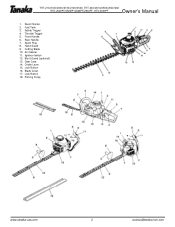
Recoil Starter 2. Throttle Trigger 5. Blunt Guard (optional) 13. Choke Lever 15. Spark Plug 8. Cutting Blade 10. Hand Guard 9. Ignition Switch 12. Rear Handle 7. Safety Trigger 4. Gear Case 14. Air Cleaner 11. Lock Button 16. Priming Pump www.tanaka-usa.com 2 custsvc@tanaka-ism.com Lock Button 18. THT-210/210S/2000/2100/2120/2520, THT-240/2510/2530/2540/262 HTD-2520PF/2522PF/2526PF/2530PF, HTS-2530PF Owner's Manual 1. Fuel Tank 3. Front Handle 6. Blade Cover 17.
Recoil Starter 2. Throttle Trigger 5. Blunt Guard (optional) 13. Choke Lever 15. Spark Plug 8. Cutting Blade 10. Hand Guard 9. Ignition Switch 12. Rear Handle 7. Safety Trigger 4. Gear Case 14. Air Cleaner 11. Lock Button 16. Priming Pump www.tanaka-usa.com 2 custsvc@tanaka-ism.com Lock Button 18. THT-210/210S/2000/2100/2120/2520, THT-240/2510/2530/2540/262 HTD-2520PF/2522PF/2526PF/2530PF, HTS-2530PF Owner's Manual 1. Fuel Tank 3. Front Handle 6. Blade Cover 17.
Owner's Manual
Page 4
... run the engine inside a closed room or building. Tool Safety • Inspect the entire tool before the unit is set down. • When operation is prolonged, take care and use . Therefore, continual and regular users should monitor closely the condition of life, if instructions are not followed. Cutting Safety • Do not cut before starting engine. • Stop engine before removing fuel cap. • Empty the fuel tank before using...
... run the engine inside a closed room or building. Tool Safety • Inspect the entire tool before the unit is set down. • When operation is prolonged, take care and use . Therefore, continual and regular users should monitor closely the condition of life, if instructions are not followed. Cutting Safety • Do not cut before starting engine. • Stop engine before removing fuel cap. • Empty the fuel tank before using...
Owner's Manual
Page 5
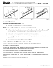
... blade-fixing bolts from the cutting-blade end to be seated, then loosen the bolts approx. 1/2 turn . 5. www.tanaka-usa.com 4 custsvc@tanaka-ism.com Remove the four washers and nuts (1) from power head side. Set the handle B (3) on the guide bar, then finger tighten the three nuts. 3. Set the blunt guard on the longest bolt (Single sided blade) and finger tighten with the washer and nut. 4. Remove the four nuts (1) (in case of Handle B installation...
... blade-fixing bolts from the cutting-blade end to be seated, then loosen the bolts approx. 1/2 turn . 5. www.tanaka-usa.com 4 custsvc@tanaka-ism.com Remove the four washers and nuts (1) from power head side. Set the handle B (3) on the guide bar, then finger tighten the three nuts. 3. Set the blunt guard on the longest bolt (Single sided blade) and finger tighten with the washer and nut. 4. Remove the four nuts (1) (in case of Handle B installation...
Owner's Manual
Page 6
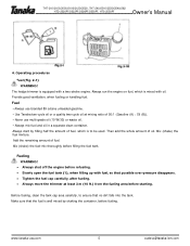
... the fuel cap carefully, after fueling. • Always move the trimmer at mixing ratio of fuel, which is to ensure that the fuel is well mixed by filling half the amount of 50:1 (Gasoline (A) : Oil (B)). • Never use branded 89 octane unleaded gasoline. • Use Tanaka two-cycle oil or a quality two-cycle oil at least 3 m (10 ft.) from the fueling area before filling the fuel tank. Always run the engine on fuel...
... the fuel cap carefully, after fueling. • Always move the trimmer at mixing ratio of fuel, which is to ensure that the fuel is well mixed by filling half the amount of 50:1 (Gasoline (A) : Oil (B)). • Never use branded 89 octane unleaded gasoline. • Use Tanaka two-cycle oil or a quality two-cycle oil at least 3 m (10 ft.) from the fueling area before filling the fuel tank. Always run the engine on fuel...
Owner's Manual
Page 7
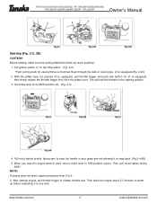
... starting engine, pull throttle trigger to any load. NOTE! Then pull recoil starter briskly again. Set ignition switch (1) to 5. 6. www.tanaka-usa.com 6 custsvc@tanaka-ism.com Before starting, make sure the cutting attachment does not touch anything. 1. With the safety lever (2) pressed (if so equipped), pull throttle trigger and push lock button (3) (if so equipped), then slowly release the throttle trigger first, then the safety lever. If engine does not start , return choke lever to CLOSED position...
... starting engine, pull throttle trigger to any load. NOTE! Then pull recoil starter briskly again. Set ignition switch (1) to 5. 6. www.tanaka-usa.com 6 custsvc@tanaka-ism.com Before starting, make sure the cutting attachment does not touch anything. 1. With the safety lever (2) pressed (if so equipped), pull throttle trigger and push lock button (3) (if so equipped), then slowly release the throttle trigger first, then the safety lever. If engine does not start , return choke lever to CLOSED position...
Owner's Manual
Page 8
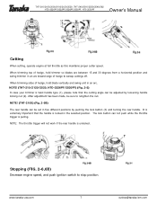
... nut. Stopping (FIG. 2-6,6B) Decrease engine speed, and push ignition switch to sweep cuttings off. THT-210/210S/2000/2100/2120/2520, THT-240/2510/2530/2540/262 HTD-2520PF/2522PF/2526PF/2530PF, HTS-2530PF Owner's Manual Cutting When cutting, operate engine at full throttle as this maintains proper cutter speed. It is extremely important that the cutting angle can not push while the throttle trigger is unlocked. The lock...
... nut. Stopping (FIG. 2-6,6B) Decrease engine speed, and push ignition switch to sweep cuttings off. THT-210/210S/2000/2100/2120/2520, THT-240/2510/2530/2540/262 HTD-2520PF/2522PF/2526PF/2530PF, HTS-2530PF Owner's Manual Cutting When cutting, operate engine at full throttle as this maintains proper cutter speed. It is extremely important that the cutting angle can not push while the throttle trigger is unlocked. The lock...
Owner's Manual
Page 9
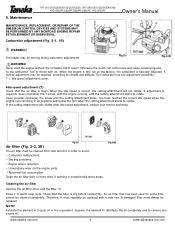
... the air filter is mixed with the engine running, until the cutting attachment stops. NOTE! In the carburetor, fuel is clean. Check that the filter is correct, the cutting attachment will not rotate. Never start the engine without the complete clutch cover! The blades may be replaced with a new one adjustment possibility: T = Idle speed adjustment screw. Therefore, it in order to remove any excess oil. Otherwise the clutch can come loose and cause personal injuries. A damaged filter must be replaced. www.tanaka...
... the air filter is mixed with the engine running, until the cutting attachment stops. NOTE! In the carburetor, fuel is clean. Check that the filter is correct, the cutting attachment will not rotate. Never start the engine without the complete clutch cover! The blades may be replaced with a new one adjustment possibility: T = Idle speed adjustment screw. Therefore, it in order to remove any excess oil. Otherwise the clutch can come loose and cause personal injuries. A damaged filter must be replaced. www.tanaka...
Owner's Manual
Page 10
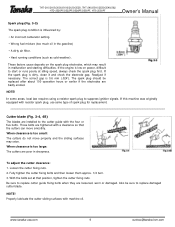
.... 1/2 turn. 3. www.tanaka-usa.com 9 custsvc@tanaka-ism.com With the bolts set at idling speed, always check the spark plug first. Also be replaced after about 100 operation hours or earlier if the electrodes are tightened with the four or five bolts. These factors cause deposits on power, difficult to the cutter guide with a clearance so that position, tighten the cutter fixing nuts. The correct gap is...
.... 1/2 turn. 3. www.tanaka-usa.com 9 custsvc@tanaka-ism.com With the bolts set at idling speed, always check the spark plug first. Also be replaced after about 100 operation hours or earlier if the electrodes are tightened with the four or five bolts. These factors cause deposits on power, difficult to the cutter guide with a clearance so that position, tighten the cutter fixing nuts. The correct gap is...
Owner's Manual
Page 11
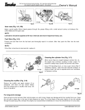
... fuel tank. Cover the unit and store it . THT-210/210S/2000/2100/2120/2520, THT-240/2510/2530/2540/262 HTD-2520PF/2522PF/2526PF/2530PF, HTS-2530PF Owner's Manual Gear case (Fig. 3-5, 5B) Apply a good quality lithium based grease through the spark plug hole, and spin the engine over several times to distribute oil. NOTE! Cleaning the muffler (Fig. 3-8) Remove the muffler and spark arrestor (if so equipped), and clean...
... fuel tank. Cover the unit and store it . THT-210/210S/2000/2100/2120/2520, THT-240/2510/2530/2540/262 HTD-2520PF/2522PF/2526PF/2530PF, HTS-2530PF Owner's Manual Gear case (Fig. 3-5, 5B) Apply a good quality lithium based grease through the spark plug hole, and spin the engine over several times to distribute oil. NOTE! Cleaning the muffler (Fig. 3-8) Remove the muffler and spark arrestor (if so equipped), and clean...
Owner's Manual
Page 12
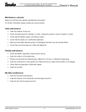
... 11 custsvc@tanaka-ism.com Monthly maintenance • Rinse the fuel tank with grease. • Clean the air filter. For further information please contact your service dealer. THT-210/210S/2000/2100/2120/2520, THT-240/2510/2530/2540/262 HTD-2520PF/2522PF/2526PF/2530PF, HTS-2530PF Owner's Manual Maintenance schedule Below you will find some general maintenance instructions. Adjust it to 0.6 mm, or change the spark plug. • Clean the...
... 11 custsvc@tanaka-ism.com Monthly maintenance • Rinse the fuel tank with grease. • Clean the air filter. For further information please contact your service dealer. THT-210/210S/2000/2100/2120/2520, THT-240/2510/2530/2540/262 HTD-2520PF/2522PF/2526PF/2530PF, HTS-2530PF Owner's Manual Maintenance schedule Below you will find some general maintenance instructions. Adjust it to 0.6 mm, or change the spark plug. • Clean the...


