
Owner's Manual
Page 2
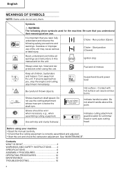
... manual carefully. • Check that you understand their meaning before use the cutting attachment min-1 whose max rpm is correctly assembled and adjusted. • Start the unit and check the carburetor adjustment. Do not attach handle above this unit. Run position (Open) Choke - Symbols WARNING The following safety precautions and warnings. Guaranteed Sound power 4 level Hot surface - Contents WHAT IS WHAT 3 WARNINGS AND SAFETY INSTRUCTIONS ........ 4 SPECIFICATIONS 6 ASSEMBLY PROCEDURES 8 OPERATING PROCEDURES 10 MAINTENANCE 12 TROUBLESHOOTING...
... manual carefully. • Check that you understand their meaning before use the cutting attachment min-1 whose max rpm is correctly assembled and adjusted. • Start the unit and check the carburetor adjustment. Do not attach handle above this unit. Run position (Open) Choke - Symbols WARNING The following safety precautions and warnings. Guaranteed Sound power 4 level Hot surface - Contents WHAT IS WHAT 3 WARNINGS AND SAFETY INSTRUCTIONS ........ 4 SPECIFICATIONS 6 ASSEMBLY PROCEDURES 8 OPERATING PROCEDURES 10 MAINTENANCE 12 TROUBLESHOOTING...
Owner's Manual
Page 3
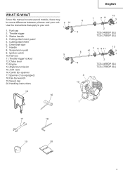
... (SL) 7 8 9 11 6 15 13 3 1 2 4 TCG 24EBDP (SL) TCG 27EBDP (SL) 3 12 1 17 18 19 20 3 Use the instructions that apply to your unit. Starter handle 4. Handle 8. Ignition switch 10. Suspension eyelet 9. English WHAT IS WHAT Since this manual covers several models, there may be some difference between pictures and your unit. 5 14 1. Harness 5 11.Throttle trigger lockout 12.Choke lever 13. Cutting attachment 6. Throttle trigger 3. Drive shaft tube 7. Cutting attachment guard 5. Fuel cap 2.
... (SL) 7 8 9 11 6 15 13 3 1 2 4 TCG 24EBDP (SL) TCG 27EBDP (SL) 3 12 1 17 18 19 20 3 Use the instructions that apply to your unit. Starter handle 4. Handle 8. Ignition switch 10. Suspension eyelet 9. English WHAT IS WHAT Since this manual covers several models, there may be some difference between pictures and your unit. 5 14 1. Harness 5 11.Throttle trigger lockout 12.Choke lever 13. Cutting attachment 6. Throttle trigger 3. Drive shaft tube 7. Cutting attachment guard 5. Fuel cap 2.
Owner's Manual
Page 4
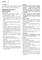
.... ○ Replace parts that the fuel be signaling a problem. Unit/machine safety ○ Inspect the entire unit/machine before storing the unit/ machine. Remove safety equipment immediately upon shutting off engine. ○ Wear head protection. ○ Never start or run the engine inside a closed environment, such as recommended for which is properly attached. ○ Keep others away when making carburetor adjustments. ○ Use only...
.... ○ Replace parts that the fuel be signaling a problem. Unit/machine safety ○ Inspect the entire unit/machine before storing the unit/ machine. Remove safety equipment immediately upon shutting off engine. ○ Wear head protection. ○ Never start or run the engine inside a closed environment, such as recommended for which is properly attached. ○ Keep others away when making carburetor adjustments. ○ Use only...
Owner's Manual
Page 5
... or loss of injury from the cutting attachment. ○ Always carry a first-aid kit when operating any material other than grass and brush. ○ Clear the area to wear eye protection. CAUTION Indicates a possibility of fuel, damage or injury. Bystanders should be encouraged to be cut any power equipment. ○ Never start or run the engine inside a closed room or building...
... or loss of injury from the cutting attachment. ○ Always carry a first-aid kit when operating any material other than grass and brush. ○ Clear the area to wear eye protection. CAUTION Indicates a possibility of fuel, damage or injury. Bystanders should be encouraged to be cut any power equipment. ○ Never start or run the engine inside a closed room or building...
Owner's Manual
Page 6
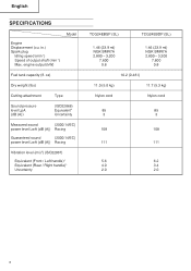
in.) Spark plug Idling speed (min-1) Speed of output shaft (min-1) Max. English SPECIFICATIONS Model Engine Displacement (cu. engine output (kW) Fuel tank capacity (fl. oz) Dry weight (Ibs) Cutting attachment Type Sound pressure level LpA (dB (A)) (ISO22868) Equivalent* Uncertainty Measured sound (2000/14/EC) power level LwA (dB (A)) Racing Guaranteed sound (2000/14/EC) power level LwA (dB (A)) Racing Vibration level (m/s2) (ISO22867) Equivalent (Front / Left handle)* Equivalent (Rear / Right handle)* Uncertainty TCG24EBSP (SL) TCG24EBDP...
in.) Spark plug Idling speed (min-1) Speed of output shaft (min-1) Max. English SPECIFICATIONS Model Engine Displacement (cu. engine output (kW) Fuel tank capacity (fl. oz) Dry weight (Ibs) Cutting attachment Type Sound pressure level LpA (dB (A)) (ISO22868) Equivalent* Uncertainty Measured sound (2000/14/EC) power level LwA (dB (A)) Racing Guaranteed sound (2000/14/EC) power level LwA (dB (A)) Racing Vibration level (m/s2) (ISO22867) Equivalent (Front / Left handle)* Equivalent (Rear / Right handle)* Uncertainty TCG24EBSP (SL) TCG24EBDP...
Owner's Manual
Page 7
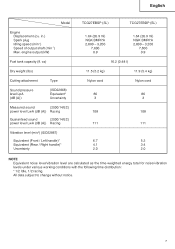
English Model Engine Displacement (cu. engine output (kW) Fuel tank capacity (fl. oz) Dry weight (Ibs) Cutting attachment Type Sound pressure level LpA (dB (A)) (ISO22868) Equivalent* Uncertainty Measured sound (2000/14/EC) power level LwA (dB (A)) Racing Guaranteed sound (2000/14/EC) power level LwA (dB (A)) Racing Vibration level (m/s2) (ISO22867) Equivalent (Front / Left handle)* Equivalent (Rear / Right handle)* Uncertainty TCG27EBSP (SL) TCG27EBDP (SL) 1.64 (26.9 ml) NGK BMR7A 2,800...
English Model Engine Displacement (cu. engine output (kW) Fuel tank capacity (fl. oz) Dry weight (Ibs) Cutting attachment Type Sound pressure level LpA (dB (A)) (ISO22868) Equivalent* Uncertainty Measured sound (2000/14/EC) power level LwA (dB (A)) Racing Guaranteed sound (2000/14/EC) power level LwA (dB (A)) Racing Vibration level (m/s2) (ISO22867) Equivalent (Front / Left handle)* Equivalent (Rear / Right handle)* Uncertainty TCG27EBSP (SL) TCG27EBDP (SL) 1.64 (26.9 ml) NGK BMR7A 2,800...
Owner's Manual
Page 8
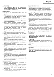
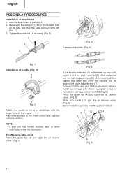
.... 5 8 English ASSEMBLY PROCEDURES 4 Installation of handle (Fig. 2) Fig. 2 Attach the handle to the drive shaft tube with the parts installed. 7 6 10 11 5 NOTE If your unit, screw it . 2. Make sure the lock pin (1) fits in place of tube and that the tube will not come with the angle towards the engine. Tighten the knob nut (3) securely. (Fig. 1) 1 3 2 Fig. 3 Connect stop cords (12) into the cable adjuster stay...
.... 5 8 English ASSEMBLY PROCEDURES 4 Installation of handle (Fig. 2) Fig. 2 Attach the handle to the drive shaft tube with the parts installed. 7 6 10 11 5 NOTE If your unit, screw it . 2. Make sure the lock pin (1) fits in place of tube and that the tube will not come with the angle towards the engine. Tighten the knob nut (3) securely. (Fig. 1) 1 3 2 Fig. 3 Connect stop cords (12) into the cable adjuster stay...
Owner's Manual
Page 9
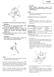
...;cations Type of the button, change the new parts immediately. (Fig. 8) 13 14 Fig. 7 NOTE The guard bracket may cause serious personal injury. 1. Install the cutting attachment guard to the guard bracket, which also secures the guard to unit. ● lf unit is a hole in the bottom (14) of Code No. Never use Tanaka nylon cutting line. Fig. 8 ○ The cutting head must be securely mounted to the gear...
...;cations Type of the button, change the new parts immediately. (Fig. 8) 13 14 Fig. 7 NOTE The guard bracket may cause serious personal injury. 1. Install the cutting attachment guard to the guard bracket, which also secures the guard to unit. ● lf unit is a hole in the bottom (14) of Code No. Never use Tanaka nylon cutting line. Fig. 8 ○ The cutting head must be securely mounted to the gear...
Owner's Manual
Page 10
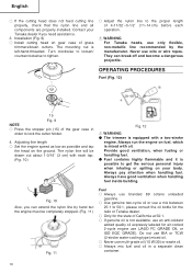
... grass trimmers/brush cutters. Fig. 10 Also, you need assistance. 3. English ○ If the cutting head does not feed cutting line properly, check that the nylon line and all components are properly installed. They can extend the nylon line by the manufacturer. Always run the engine on your Tanaka dealer if you can break off and become a dangerous projectile. Always pay attention when handling fuel. Adjusting line length ○ Set...
... grass trimmers/brush cutters. Fig. 10 Also, you need assistance. 3. English ○ If the cutting head does not feed cutting line properly, check that the nylon line and all components are properly installed. They can extend the nylon line by the manufacturer. Always run the engine on your Tanaka dealer if you can break off and become a dangerous projectile. Always pay attention when handling fuel. Adjusting line length ○ Set...
Owner's Manual
Page 11
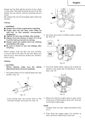
... cutting attachment does not touch anything. 1. Starting CAUTION Before starting . ● Always wash any fuel leakage after refueling. Pull recoil starter briskly, taking care to keep the handle in your grasp and not allowing it to forward away from clothing immediately with fuel, so that the fuel is to check for any spilled fuel from stop position. (Fig. 13) Fig. 15 3. Set choke lever (20) to START position...
... cutting attachment does not touch anything. 1. Starting CAUTION Before starting . ● Always wash any fuel leakage after refueling. Pull recoil starter briskly, taking care to keep the handle in your grasp and not allowing it to forward away from clothing immediately with fuel, so that the fuel is to check for any spilled fuel from stop position. (Fig. 13) Fig. 15 3. Set choke lever (20) to START position...
Owner's Manual
Page 12
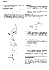
...; Cut grass from right to spin after the engine is stopped or power control is set down . Extended time of use at over 6,500 min-1. Semi-auto cutting head ○ When cutting, operate engine at an idle for efficient cutting. Check that the attachment and related parts are undamaged. The cutting attachment turns counterclockwise, therefore, be advised to operate the unit from right to left . Stopping (Fig. 20) Decrease engine speed and run at...
...; Cut grass from right to spin after the engine is stopped or power control is set down . Extended time of use at over 6,500 min-1. Semi-auto cutting head ○ When cutting, operate engine at an idle for efficient cutting. Check that the attachment and related parts are undamaged. The cutting attachment turns counterclockwise, therefore, be advised to operate the unit from right to left . Stopping (Fig. 20) Decrease engine speed and run at...
Owner's Manual
Page 13
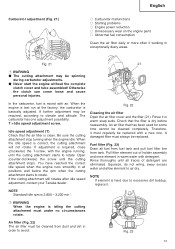
... be cleaned from tank. You have reached the correct idle speed when the engine runs smoothly in all fuel from fuel tank and pull fuel filter line from dust and dirt in warm water with air. WARNING When the engine is required, close (clockwise) the T-screw, with a new one adjustment possibility: T = Idle speed adjustment screw. Rinse thoroughly until the cutting attachment stops. Fig. 22 Cleaning the air filter Open the air filter cover and...
... be cleaned from tank. You have reached the correct idle speed when the engine runs smoothly in all fuel from fuel tank and pull fuel filter line from dust and dirt in warm water with air. WARNING When the engine is required, close (clockwise) the T-screw, with a new one adjustment possibility: T = Idle speed adjustment screw. Rinse thoroughly until the cutting attachment stops. Fig. 22 Cleaning the air filter Open the air filter cover and...
Owner's Manual
Page 14
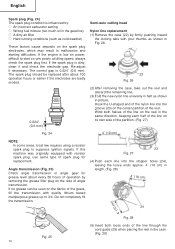
...) ○ A dirty air filter ○ Hard running conditions (such as shown in malfunction and starting difficulties. Angle transmission (Fig. 25) Check angle transmission or angle gear for replacement. The spark plug should be seen on the side of spark plug for grease level about 100 operation hours or earlier if the electrodes are badly eroded. 0.024" (0.6 mm) Semi-auto cutting head Nylon line replacement (1) Remove the case...
...) ○ A dirty air filter ○ Hard running conditions (such as shown in malfunction and starting difficulties. Angle transmission (Fig. 25) Check angle transmission or angle gear for replacement. The spark plug should be seen on the side of spark plug for grease level about 100 operation hours or earlier if the electrodes are badly eroded. 0.024" (0.6 mm) Semi-auto cutting head Nylon line replacement (1) Remove the case...

Owner's Manual
Page 15
... general maintenance instructions. Adjust it . 15 Then push the case securely until it and check the electrode gap. Change the guard in the case, try to line up the stopper holes (24) with grease up to 0.024˝ (0.6 mm), or change the spark plug. ○ Check that the cap locking tabs (26) on the case meet the long holes (27) on the cover. An off-centre cutting attachment...
... general maintenance instructions. Adjust it . 15 Then push the case securely until it and check the electrode gap. Change the guard in the case, try to line up the stopper holes (24) with grease up to 0.024˝ (0.6 mm), or change the spark plug. ○ Check that the cap locking tabs (26) on the case meet the long holes (27) on the cover. An off-centre cutting attachment...
Owner's Manual
Page 16
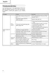
... tool does not operate normally. Condition Fuel system Engine does not start Electrical system Other Cause Remedy Fuel tank is empty or fuel level is Fill the fuel tank with the correct fuel low mix (25:1-50:1) Fuel tank contains old fuel (offensive odor) Replace with new fuel Too much fuel is absorbed and spark plug is wet 1.Disconnect the spark plug and allow to dry 2.Pull the starter handle 5 or 6 times to remove the surplus fuel 3.Attach the spark plug 4.Set the choke lever to RUN position and pull...
... tool does not operate normally. Condition Fuel system Engine does not start Electrical system Other Cause Remedy Fuel tank is empty or fuel level is Fill the fuel tank with the correct fuel low mix (25:1-50:1) Fuel tank contains old fuel (offensive odor) Replace with new fuel Too much fuel is absorbed and spark plug is wet 1.Disconnect the spark plug and allow to dry 2.Pull the starter handle 5 or 6 times to remove the surplus fuel 3.Attach the spark plug 4.Set the choke lever to RUN position and pull...
Owner's Manual
Page 17
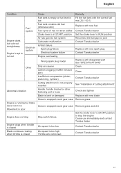
...level is Fill the fuel tank with the correct fuel low mix (25:1-50:1) Fuel tank contains old fuel (offensive odor) Replace with new fuel Two-cycle oil has not been added Contact Tanaka dealer Choke lever is in START position Set the choke lever to RUN position Air has got into fuel system Reconnect the fuel pipe or joint Carburetor malfunction Contact Tanaka dealer Ignition failure Spark plug failure Replace with new spark plug Electrical system failure Contact Tanaka dealer Engine overheating Wrong spark plug model Replace with designated part See "SPECIFICATIONS" Dirty air...
...level is Fill the fuel tank with the correct fuel low mix (25:1-50:1) Fuel tank contains old fuel (offensive odor) Replace with new fuel Two-cycle oil has not been added Contact Tanaka dealer Choke lever is in START position Set the choke lever to RUN position Air has got into fuel system Reconnect the fuel pipe or joint Carburetor malfunction Contact Tanaka dealer Ignition failure Spark plug failure Replace with new spark plug Electrical system failure Contact Tanaka dealer Engine overheating Wrong spark plug model Replace with designated part See "SPECIFICATIONS" Dirty air...
Parts List
Page 4
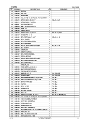
... 1 7 6696958 HEX. SOCKET BOLT (W/WASHERS) M5 2 23 6698405 CARBURETOR PACKING 1 24 6691337 SWIVEL CAP 1 25 6600326 CARBURETOR ASS'Y WYC-37 1 INCLUD.26-40 26 6699287 CABLE ADJUST STAY 1 27 6696830 SWIVEL 1 28 6684696 STOP RING 1 29 6684692 PUMP GASKET 1 30 6684693 PUMP DIAPHRAGM 1 31 6691242 PUMP PLATE 1 32 6685222 DIAPHRAGM COVER-METERING 1 33 6691312 SET SCREW 4 34 6696829 SET SCREW M3 X 12 2 35 6684695...
... 1 7 6696958 HEX. SOCKET BOLT (W/WASHERS) M5 2 23 6698405 CARBURETOR PACKING 1 24 6691337 SWIVEL CAP 1 25 6600326 CARBURETOR ASS'Y WYC-37 1 INCLUD.26-40 26 6699287 CABLE ADJUST STAY 1 27 6696830 SWIVEL 1 28 6684696 STOP RING 1 29 6684692 PUMP GASKET 1 30 6684693 PUMP DIAPHRAGM 1 31 6691242 PUMP PLATE 1 32 6685222 DIAPHRAGM COVER-METERING 1 33 6691312 SET SCREW 4 34 6696829 SET SCREW M3 X 12 2 35 6684695...
Parts List
Page 5
... 6684674 STARTER ROPE 3.5 X 860 1 74 6684680 STARTER HANDLE 1 75 NAME PLATE 1 76 6698921 TANK MARK LABEL (50:1) 1 77 6600323 MUFFLER HEAT COVER 1 78 6600325 TAPPING SCREW D4 X 10 2 * 79 6600327 MARK PLATE (T) 1 FOR EUROPE * 80 6699000 PRIMER LABEL 1 FOR EUROPE * 91 6699195 MACHINE SCREW M5 X 20 (BLACK) 2 FOR (SL) * 92 6699194 P TIGTH SCREW D4 X 20 (BLACK) 4 FOR (SL) * 93 6699197 SWITCH WIRE SET 1 FOR...
... 6684674 STARTER ROPE 3.5 X 860 1 74 6684680 STARTER HANDLE 1 75 NAME PLATE 1 76 6698921 TANK MARK LABEL (50:1) 1 77 6600323 MUFFLER HEAT COVER 1 78 6600325 TAPPING SCREW D4 X 10 2 * 79 6600327 MARK PLATE (T) 1 FOR EUROPE * 80 6699000 PRIMER LABEL 1 FOR EUROPE * 91 6699195 MACHINE SCREW M5 X 20 (BLACK) 2 FOR (SL) * 92 6699194 P TIGTH SCREW D4 X 20 (BLACK) 4 FOR (SL) * 93 6699197 SWITCH WIRE SET 1 FOR...

Parts List
Page 6
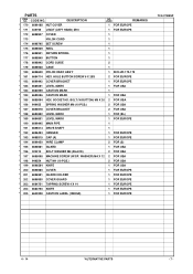
... TANK CAP CHAIN 1 130 6698931 FUEL GROMMET 1 131 6699558 SPACER 1 * 132 6600317 TANK (B) 1 * 132 6698377 TANK 1 FOR USA 133 6684620 PUMP FILTER BODY COMP. 1 134 6696949 CLIP 1 135 6694787 STAND 1 136 6696557 FLANGE BOLT 2 137 6698991 BOLT (W/FLANGE) L27.8 1 * 151 6699446 THROTTLE LEVER (B) 1 FOR (S) * 152 6699448 LOOP HANDLE (W/BARRIER) 1 FOR EUROPE (SL) * 153 6699449 LOOP HANDLE 1 FOR USA * 154 6684709 HEX. DESCRIPTION 110 6699434 CLUTCH SHAFT...
... TANK CAP CHAIN 1 130 6698931 FUEL GROMMET 1 131 6699558 SPACER 1 * 132 6600317 TANK (B) 1 * 132 6698377 TANK 1 FOR USA 133 6684620 PUMP FILTER BODY COMP. 1 134 6696949 CLIP 1 135 6694787 STAND 1 136 6696557 FLANGE BOLT 2 137 6698991 BOLT (W/FLANGE) L27.8 1 * 151 6699446 THROTTLE LEVER (B) 1 FOR (S) * 152 6699448 LOOP HANDLE (W/BARRIER) 1 FOR EUROPE (SL) * 153 6699449 LOOP HANDLE 1 FOR USA * 154 6684709 HEX. DESCRIPTION 110 6699434 CLUTCH SHAFT...
Parts List
Page 7
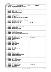
... *ALTERNATIVE PARTS - 7 - CODE NO. * 170 6699188 NUT COVER DESCRIPTION NO. SOCKET HD. PARTS ITEM NO. USED REMARKS 1 FOR EUROPE * 171 335759 U-NUT (LEFT HAND) M10 1 FOR EUROPE 172 6698937 COVER 1 173 NYLON CORD 1 174 6698795 SET SCREW 1 175 6698939 REEL 1 176 6698941 RETURN SPRING 1 177 6698940 BUTTON 1 178 6698942 CORD GUIDE 2 179 6698938 CASE 1 180 6698639 NYLON HEAD ASS'Y 1 INCLUD.172-179 * 181 6684714 HEX. BOLT...
... *ALTERNATIVE PARTS - 7 - CODE NO. * 170 6699188 NUT COVER DESCRIPTION NO. SOCKET HD. PARTS ITEM NO. USED REMARKS 1 FOR EUROPE * 171 335759 U-NUT (LEFT HAND) M10 1 FOR EUROPE 172 6698937 COVER 1 173 NYLON CORD 1 174 6698795 SET SCREW 1 175 6698939 REEL 1 176 6698941 RETURN SPRING 1 177 6698940 BUTTON 1 178 6698942 CORD GUIDE 2 179 6698938 CASE 1 180 6698639 NYLON HEAD ASS'Y 1 INCLUD.172-179 * 181 6684714 HEX. BOLT...


